Published by Tomasz SAMBORSKI, Andrzej ZBROWSKI, Stanisław KOZIOŁ,
Instytut Technologii Eksploatacji – Państwowy Instytut Badawczy
Abstract. The introduced device allows performance of the research in the rotary testing of the resistance to the surface discharge and erosion of the polymeric insulators according to PN-EN 62217:2007. The applied control system of the operation of the device allows controlling of the parameters of testing (rotary speed, duration time) in the wide range. The performance of tests of resistance to the surface discharge and erosion of the polymeric insulators in the wider range of the parameters than defined by the standard allows more effective detection of the weak points of the construction, which could cause the damage of the insulator during exploitation.
Streszczenie. W artykule przedstawiono metody badań odporności na wyładowania pełzne i erozję polimerowych izolatorów energetycznych zgodne z PN-EN 62217:2007 ze szczególnym uwzględnieniem próby kołowej. Opisano zaprojektowane i wykonane w Instytucie Technologii Eksploatacji – PIB w Radomiu urządzenie do próby kołowej. Umożliwia ono przeprowadzanie długotrwałych badań izolatorów wsporczych i liniowych wyposażonych w elementy mocujące dowolnej konstrukcji. (System do testowania odporności na wyładowania pełzne i erozję polimerowych izolatorów energetycznych)
Keywords: support insulators, line insulators, creeping discharge effect, insulators testing.
Słowa kluczowe: izolatory wsporcze, izolatory liniowe, wyładowania pełzne, badania izolatorów.
Introduction
The insulators made of polymeric ceramics are technical and economical alternative for the insulators made of the porcelain, particularly for their perfect electro-insulating properties, low material costs and the energy saving production process. Most often, the polymeric line insulators are smaller in the diameter than the porcelain or glass insulators. Thanks to that higher resistance to the breakdown through shape or to the water absorption. Taking into consideration the insulation properties of the insulators the hydrophobic properties of insulator are the key factor [1].
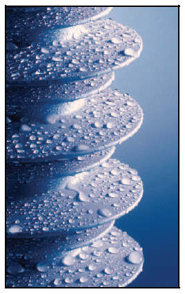
Fig. 1. The hydrophobic properties of the surface of the polymeric insulator [1]
The processes of dynamic losing and regaining of the hydrophobic properties and their strong dependence on the material (including basic components, filler and additives) and on the production technology are the areas of the permanent development. If the hydrophobicity is lost, the insulator “should be protected” against intense wear-out (erosion, surface currents) by the second protection mechanism of the material. It is best assessed by performing tests for resistance to surface currents and erosion.
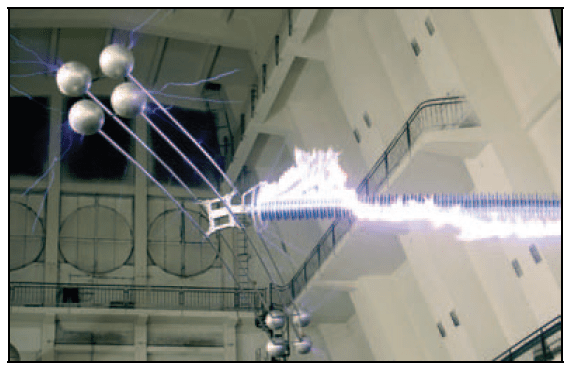
Fig. 2. High voltage testing (PFISTERER SEFAG)
For ensuring the high level of technical safety of the power systems the standard obligatory tests are performed for testing the resistance of the construction to the surface discharge and erosion of the polymeric power insulators. The performed certification tests allow elimination of such construction of insulators, materials or production technologies that are not good enough for application in high voltage techniques occurring in standard work conditions.
In the electrical aspect the task of the insulator is the insulation of the high voltage elements from the grounded elements or mutual insulation of two high voltage elements against the spark passing. Simply put, the passing of spark might be the result of too high voltage or pollution. When the passing route determines the action during the overvoltage, the shape (geometry) of the insulator and the reaction of the surface of the insulator to the water absorption are the critical factors for the resistance to pollution.
The polymeric insulators are made of single insulation material (synthetic resin insulators) or of two or more insulation materials (composite insulators). The construction materials are most often the cross-linked organic materials made of the coal of silicon components. The insulation materials might be composed of the organic materials with additions of different organic and non-organic materials such as fillers and solvents.
The construction of the polymeric insulator is generally defined by:
– materials for the core and the cover and method for their production,
– materials and construction of the holding elements and the method for their montage,
– the thickness of the cover on the core (including the middle layer, if exists).
For the elimination of the construction of insulators, materials or production technologies that are not suitable for applications in high voltage the construction tests are performed. The range of the construction tests is selected to make possible the estimation of the time influence on the electrical properties of the complete polymeric insulator and its components (core material, cover material, border surfaces etc.) that ensure the expected life-span in normal work and environmental conditions (Table 1).
Table 1. Normal environmental conditions
| Conditions | Indoor insulation | Outdoor insulation |
|---|---|---|
| Maximal ambient temperature | Not higher than 40°C, and its average value measured within 24 hours not higher than 35°C | Not higher than 40°C, and its average value measured within 24 hours not higher than 35°C |
| Minimal ambient temperature | -25°C | -40°C |
| Vibration | Insignificant vibration caused by external phenomena or by underground vibration | Insignificant vibration caused by external phenomena or by underground vibration |
| Sun radiation [1] | Insignificant | Up to 1 000 W/m2 |
| Air pollution | No visible pollution with dust, smoke, flammable gas or corrosive gas, fumes or salt | Possible pollution with dust, smoke, flammable gas or corrosive gas, fumes or salt (Not higher than “high level” defined by IEC 60815 [4]) |
| Humidity | Average relative humidity, measured within 24 hours not higher than 95%; measured within a month not higher than 95%. Steam condensation might occur |
The tests of resistance to the surface discharge and erosion that are part of the construction research are treated as the test resulting in selection and rejection of improper materials or constructions. The tests include only a part of complex loads occurring during the work of the insulator and are not the basis for assessment of the durability of the insulators [3].
Testing the resistance to the surface discharge and erosion
The composite insulators are used both for alternating current and direct current. There is no developed method for testing the insulators and their resistance to surface discharge and erosion under the direct current. The latest standard PN-EN 62217:2007 “polymeric insulators for indoor and outdoor use with a nominal voltage above 1000 V – general definitions, test methods and acceptance” defines the tests of resistance to surface discharge and erosion under the alternating current. The conducted tests are used for determination of the minimal requirements for the resistance of the cover material to generation of the conductive paths. The standard allows the choice between three methods of testing of the resistance of the construction of the insulator to the actions of the electric discharge.
The first test is the test in the salt mist, second test includes various cyclic loads and the third is a rotary test. The test in the salt mist during 1000 hours consists in the time limited effect of the salt mist on the insulator under the alternating current with net frequency and the constant voltage value [5]. The test is performed in the water and corrosion proof chamber with volume not greater than 15m3, equipped with the opening not greater than 80cm2, for natural ventilation.
In the test with different loads the tested insulators are placed in the water and corrosion proof chamber with volume not greater than 20m3. The normalised load cycle – repeated for 5000 hours – includes: testing alternating current of net frequency, simulation of the sun radiation, artificial rain, dry and wet hot air and pollution simulated with the salt mist [5, 6].
The rotary test consists in cyclic loading (30 000 cycles) of the insulators placed on the rotating holder (Fig.3). During one cycle the insulators go through four positions. Each piece stays motionless in each of four positions for about 40s. The rotation by 90° from one
position to another lasts about 8s. In the first part of the cycle the insulator is immersed in the saline solution. The second part of the cycle allows the surplus of the solution to drain which in turn allows that in the third part of the cycle the discharge occurs on the moist surface crosswise to the drying stripes. In the third part of the cycle the sample is exposed to the alternating current of the net frequency. In the last part of the cycle the surface heated by the discharge is cooling down. The testing current is connected from the testing transformer. With the load of the active current of 250mA on the high voltage side of the testing circuit the maximal drop of the output voltage should not exceed 5%.
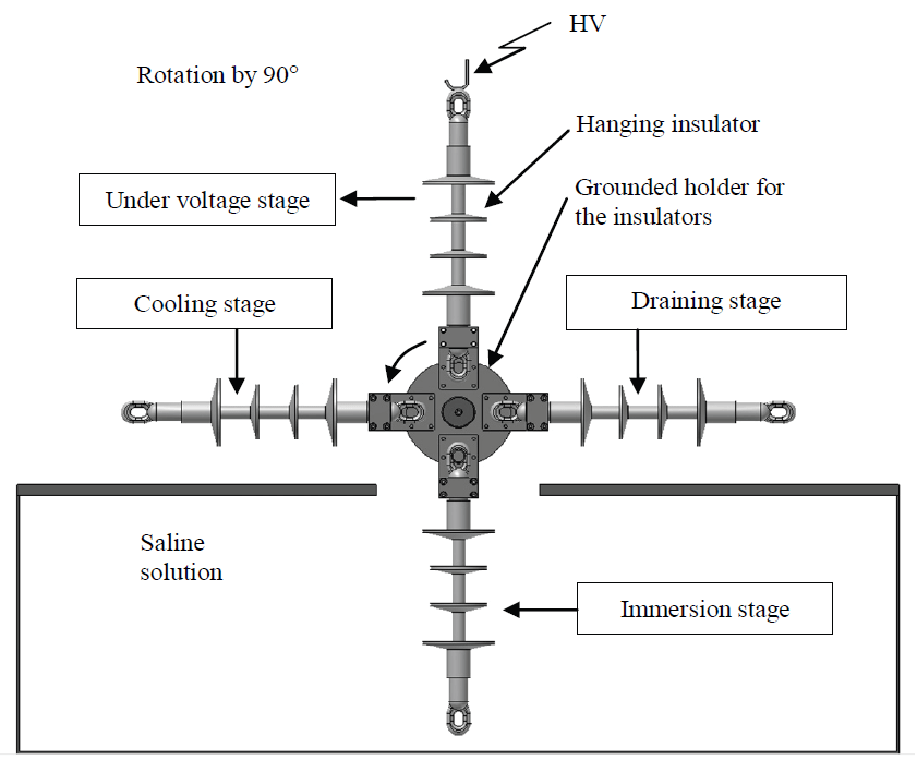
Fig. 3. The diagram of the testing stand for the rotary testing of the insulators for the resistance against the surface discharge according to PN-EN 62217:2007
In each of the presented testing methods two insulators are picked from the production line, both of identical construction and the leak path in between 500 mm and 800 mm. If there are no such insulators in the production line, a substitute should be made from the available types by installing normalised holding elements in such a way than the leak path is in the mentioned range. For the inspection reasons it is possible to stop the continued test once a week. None of the pauses should be longer than 1 hour, and its duration is not counted into the test time. One longer pause is acceptable, but no longer than 60 hours. The test time should be extended by triple the pause duration. The final report should include all the details about the pauses.
The result of the test is considered positive if on both samples:
– there are no signs of the surface discharge (megaohmmeter should be used by the voltage of 1 kV or higher, putting electrodes in the distance between 5mm and 10mm from each other along each suspected path; the resistance below 2MΩ means the damage occurred);
– in case of composite insulators – the depth of the erosion is smaller than 3mm and does not reach to the core (if that is possible);
– in case of resin insulators – the depth of the erosion is smaller than 3mm;
– there are no breakdowns of the cover or the border
surface.
The device for rotary testing
Despite the free choice of the testing method, the most popular method among the producers is the rotary method, considered to be most reliable. For the sake of inexistence of the testing apparatus for such tests and interest demonstrated by the certification unit (Institute of Power Engineering), the Institute for Sustainable Technologies in Radom has designed, produced and introduced for use in the Institute for Power Engineering in Warsaw a unique, specialised system for rotary testing according to the PNEN 62217 standard.
The construction of the device for testing of resistance to surface discharge and erosion of the polymeric insulators is presented in the figure 4.
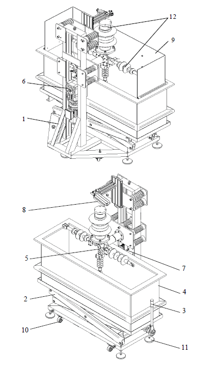
Fig. 4. The construction of the device for testing of resistance to the surface discharge and erosion of the polymeric insulators: 1 – frame, 2 – scissor lifter, 3 – lifter drive handle, 4 – saline solution tank, 5 – insulator positioning module, 6 – geared drive, 7 – belt drive, 8 – testing voltage supply module, 9 – cover, 10 – wheels, 11 – vibroinsulators, 12 – tested insulators
The stand consists of the steel frame, which is the chassis of the device, bearing the mechanical loads from the tested objects. In the front, horizontal part of the frame the scissor lifter is fixed, powered with screw drive. In the frame of the lifter the tank, of the volume of 500 dcm3, is fixed and filled with the saline solution, in which the insulators are immersed.
The precise, vertical movement of the lifter allows proper expected level of immersion of the tested insulators. The tested insulators are fixed in the positioning holder, mounted in the vertical part of the frame. The positioning holder (Fig. 5), to which the testing voltage is connected through the tested insulators, is fixed on the four support insulators connected to frame.
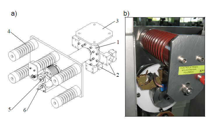
Fig. 5. The positioning module for the insulators: a) the model, b) the view, 1 – hub, 2, 3 – holders, 4 – support insulators, 5 – brush module, 6 – position sensor
For the sake of different constructions of the holing elements of the tested insulators (Fig. 6) used for bearing of the mechanical loads, the positioning module is equipped with universal prismatic holders intended for fixing of the hanging insulators and with specialised holders for the standing insulators.
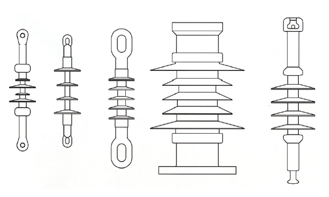
Fig. 6. Sample constructions of the insulator holders
The holders are fixed to the hub, which angular position corresponding to the particular cycles of the test is identified by the induction proximity switch. The grounding of the hub is realised by the brush module cooperating with the sliding ring.
The rotary movement of the hub of the positioning module is performed by the geared motor fixed in the vertical part of the frame through the cog belt gearbox that guarantees the insulation of the drive system from the tested object (Fig. 7). The applied drive system is intended for powering with the power inverter which allows fairly wide range of time duration for each test cycle.
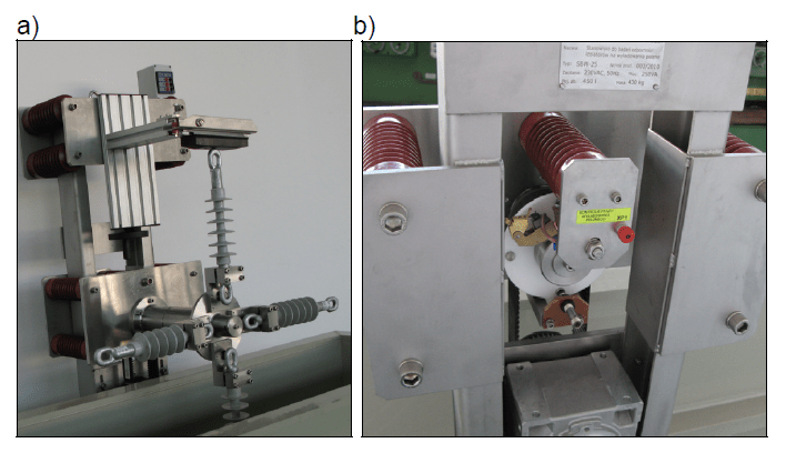
Fig. 7. The mechanism of the holder drive a) front view, b) back view
For the sake of the long time testing (30 000 cycles) it was necessary to ensure the high durability of particular construction node. The important module which decides on the proper testing process is the module of testing voltage supply (Fig. 8). The task of the module is supplying of the high voltage to the clamp of the insulator after the draining of the insulator from the saline solution. In the developed solution the role of the contacting element with the tested insulator, exposed to the mechanical wear (abrasion) and burnout, is the carbon slider used in traction networks. The slider is fixed to the swinging arm, which allows good contact to the insulator clamp, which position is controlled by the screw positioning mechanism.

Fig. 8. Testing voltage supply module: 1 – positioning module, 2 – swing arm, 3 – carbon slider, 4 – support insulator
For ensuring of the necessary mechanical safety related to the maintenance of the device it is equipped with the cover made of colourless polycarbonate, which is removed for the inspection of the insulators. Supplying of the device with high voltage requires placement of the device in the separate zone. To achieve that the device is equipped with the wheels and adaptable stands (vibroinsulators) that allow its levelling.
For the sake of the corrosive character of the environment in which the tests are performed, the device is made mostly of the acid resistant steel. The power supply circuits and the control circuits for the drive were put in the mobile control box (Fig. 9).

Fig. 9. Control box for the device
On the door of the box the control elements were placed for the control of the work of the drive module of the holder. The control of the work is performed by means of programmable relay and the inverter. Such solution allows:
– the change of the rotation speed,
– the control of the duration of each stage of the test
– the control of start and stop,
– easy start and stop of the drive,
– fast emergency stop
Verification tests
The device produced in the Institute for Sustainable Technologies – NRI in Radom (Fig. 10a) was introduced in the Laboratories of High Voltage in the Institute of Power Engineering in Warsaw, where it was tested in work (Fig. 10b).

Fig. 10. Device for rotary testing (a) and the view of the surface discharge on the tested insulator (b)
The basic tests were conducted in the conditions (Table 2) defined by the PN-EN 62217:2007. Rotary tests. The appendix A in the limited range of the duration time of the test (the duration of a full test without pauses in normalised cycle is 1600 hours).
Table 2. Test conditions
| Testing voltage | Testing alternating voltage of net frequency in kV is defined by dividing of the real leak path [mm] by 28,6 |
| Allowed content of NaCl in the de-ionised water | 1,40 kg/m3 ± 0,06 kg/m3 |
| Ambient temperature | 20 °C ± 5 K |
| Test duration | 30 000 cycles |
The performed tests confirmed the assumptions made in the range of the maintenance parameters and in the range of the construction solutions.
Summary
The introduced device allows performance of the research in the rotary testing of the resistance to the surface discharge and erosion of the polymeric insulators according to PN-EN 62217:2007.
The applied control system of the operation of the device allows controlling of the parameters of testing (rotary speed, duration time) in the wide range.
The performance of tests of resistance to the surface discharge and erosion of the polymeric insulators in the wider range of the parameters than defined by the standard allows more effective detection of the weak points of the construction, which could cause the damage of the insulator during exploitation.
The system might be used in the certification testing and the development works in new products made in companies producing the polymeric insulators.
LITERATURE
[1] izolatory silikonowe silcosil©. http://pfisterer.com/download_download/d_8833.pdf
[2] IEC 60721-1, Classification of environmental conditions – Part 1: Environmental parameters and their severities
[3] CIGRE Technical Brochure No. 142: „Natural and artificial ageing and pollution testing of polymeric insulators.”June 1999
[4] IEC 60815, Guide for the selection of insulators in respect of polluted conditions
[5] CIGRE Technical Brochure No. 142: „Natural and artificial ageing and pollution testing of polymeric insulators.”June 1999
[6] Gutman I., Hartings R.: Standard and Reduced Salinity 1000 h Salt Fog Tests on Silicone Rubber Apparatus Insulators. 10 th International Symposium on High Voltage Engineering. Montreal, Quebec, Kanada, August 25-29, 1997
Authors: dr inż. Tomasz Samborski, dr inż. Andrzej Zbrowski, dr inż. Stanisław Kozioł, Instytut Technologii Eksploatacji – PIB, ul. Pułaskiego 6/10, 26-600 Radom, E-mail: Tomasz.Samborski@itee.radom.pl.
Source & Publisher Item Identifier: PRZEGLĄD ELEKTROTECHNICZNY (Electrical Review), ISSN 0033-2097, R. 88 NR 3a/2012
