Published by Algirdas BASKYS1, 2, Vytautas BLEIZGYS1, 2, Tadas LIPINSKIS1, 2
Center for Physical Sciences and Technology (1), Vilnius Gediminas Technical University (2)
Abstract. The overvoltage in the inverter that supplies the AC induction motor, which during the deceleration operates as a generator delivering current back into the inverter DC bus, has been investigated. The investigation was performed experimentally using a special test bench. The impact of the motor deceleration rate, motor load and initial rotation velocity, at which the deceleration starts, on the overvoltage was investigated and analyzed. The obtained results were employed for the development of the overvoltage fault protection of the inverter.
Streszczenie. W przekształtniku zasilającym silniki AC powstają przepięcia w czasie zwalniania silnika. Przeprowadzona badania tego zjawiska dla różnych: prędkości zwalniania, obciążeń silnika i prędkości obrotowej (Analiza przepięć w przekształtniku zasilającym silnik)
Keywords: inverter, overvoltage, AC induction motor, motor deceleration.
Słowa kluczowe: przekształtnik, przepięcia, sinlik AC.
Introduction
The AC induction motor used in the variable speed drive based on the frequency converter can act as a generator under certain operating conditions. The inverter, which is the main block of the frequency converter, supplies the motor with the variable frequency variable amplitude three phase AC voltage. The motor rotation velocity is determined by the AC voltage frequency. If the frequency increases the motor accelerates, if it decreases – the motor decelerates. If the AC induction motor rotation velocity during the deceleration exceeds the synchronous velocity, it starts to operate as a generator delivering current back into the DC bus of the inverter through the transistors, which operate as switches of the inverter. Therefore, the capacitors of the DC bus are charged and voltage of the DC bus increases [1-3]. The maximal voltage value (overvoltage) depends on the motor deceleration rate, motor load and its inertness, capacitance of the DC bus capacitors and initial rotation velocity of the motor (rotation velocity, at which the deceleration starts). If the overvoltage of the DC bus exceeds the safe operation limits, the transistors of inverter switches, DC bus capacitors and other components used in the inverter can be damaged [3, 4]. Therefore, the problem of the overvoltage in the inverter, is topical [5]. There are lot of works, e.g. [6-9], dedicated to the investigation of the overvoltage in the inverter using simulation. However, during the frequency converter development process it is important to have accurate data, which can be obtained only experimentally. They are needed for the development of the overvoltage fault protection of the inverter.
The investigation technique
The investigation of the overvoltage in the inverter caused by the AC induction motor deceleration was performed using a special test bench. The block diagram and picture of the test bench are given in Figs.1 and 2. It includes the 4 kW AC induction motor fed from the inverter of the experimental example of the developed frequency converter. The motor drives the 5.5 kW DC generator, which acts as the motor load and is characterized by the relatively high inertness. The test bench includes the motor load torque and rotation velocity sensors and appropriate circuits for conversion of sensor signals to standard signals, which are used for measurement.
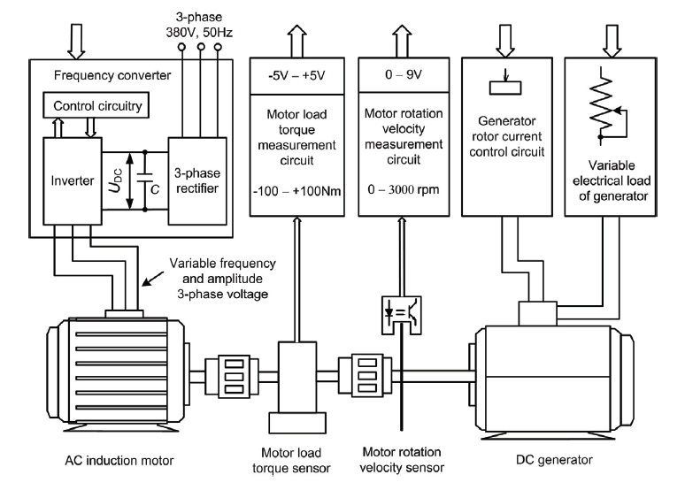

The motor load torque is controlled by the variation of the DC generator rotor current and the generator electrical load. The transients of the inverter DC bus voltage (UDC), motor load torque (M) and motor rotation velocity (Vr) have been investigated. The measurements of transients were provided using the Tektronix digital oscilloscope TPS2024.
The following investigation technique has been used. Firstly, the appropriate frequency (fp) of the inverter output voltage and deceleration rate are preset and the motor is started. Secondly, the motor load torque is fixed by variation of the rotor current and electrical load of the DC generator. After this, the motor is stopped at the assigned deceleration rate and UDC, M, Vr transients are measured. The motor deceleration rate (D) is expressed by the decrease rate of the frequency of the inverter output voltage, i.e. D has the Hz/s dimension.
The two situations can be observed during the motor deceleration when the motor acts as a generator and the DC bus capacitors are charged. The first situation is when the DC bus voltage spike does not reach the overvoltage fault protection trigger level, the second one – when the voltage spike reaches this level. In the first case the motor is stopped at the preset deceleration rate. However, if the overvoltage fault protection is triggered, the transistors of inverter switches are closed and the motor does not provide the energy to the DC bus. Therefore, the rise of the DC bus voltage is stopped, the motor is not decelerated by the inverter and, as a consequence, the motor deceleration becomes uncontrolled.
The examples of the transients of the UDC, M and Vr for the case when the overvoltage fault protection is not triggered are presented in Fig. 3. It is seen that the motor deceleration causes the DC bus voltage spike and the motor load torque decreases and becomes negative during the deceleration. Additionally, the transient of the motor load torque has oscillations.
The DC bus voltage transient example for the case when the voltage spike reaches the overvoltage fault protection trigger level is given in Fig. 4. The rising edge steepness of the voltage spike in the analyzed case is about 1.5 V/ms. When the voltage reaches the fault protection trigger level, the transistors of inverter switches are closed by the protection circuit. Since the steepness of voltage spike is relatively low, the DC bus voltage practically is fixed at the value, which corresponds to the overvoltage fault protection trigger level even in the case when overvoltage fault protection circuit with the response time up to several hundreds of microseconds is employed. This fact allows us to use slow overvoltage protection circuit, i.e. circuit, witch has low sensitivity to electromagnetic disturbances produced by the inverter.

The shape of the falling edge of the voltage spike (Fig. 4) is determined by the slow discharge of the DC bus capacitors by the frequency converter circuitry, which is fed from the DC bus voltage.
The inverter overvoltage investigation results
The investigation was accomplished at various motor load torques for the different motor deceleration rate and initial motor rotation velocity, at which the deceleration starts. The results were obtained for DC bus capacitor capacitances C = 470 and 880 µF. During the investigation the duration of UDC spike (τ) and the maximal UDC value UDCm (overvoltage) (Fig. 3) were estimated. The results are presented in Figs. 5–7. The overvoltage depends on the motor load – it decreases if the motor load increases. This can be explained by the fact that the motor even during the deceleration supplies the energy to the load and only the excess energy of the motor is supplied to the DC bus. It is seen that the overvoltage increases when the motor deceleration rate and initial rotation velocity (initial inverter output voltage frequency) increase (Figs. 5 and 6). The increment of the capacitance of the DC bus capacitors allows us to reduce the overvoltage. However, the overvoltage decrement is slight even imperceptible (compare the dependences given in Fig. 5 with the corresponding dependences presented in Fig. 6). This can be explained by the fact that the capacitor voltage is proportional to the square root of energy (E) used for the capacitor charge. Knowing the nominal DC bus voltage UDCn (in the analyzed case UDCn≈540V), the DC bus capacitance C and the amount of energy, which is supplied by the motor to the DC bus during the motor deceleration, the DC bus voltage can be calculated using a well known equation UDC=[(2E/C) + U2DCn]1/2, where E is expressed in Joules, C – in Farads and the voltage − in Volts.

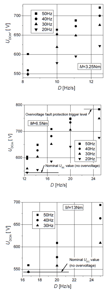
For example, if UDCn = 540V and the energy of 27.7 Joules is supplied to the 470µF DC bus capacitor, it is charged according to the given equation up to UDC = 650V. If the capacitance is increased up to 880 µF (by the 87%), the calculated voltage at the same amount of energy UDC = 595V, i.e. theoretically the voltage in the analyzed situation should decrease by 7.5% only.
The investigation of the UDC spike duration (Fig. 7) shows that it decreases when the motor initial rotation velocity (initial inverter output voltage frequency) decreases. However, the dependence of the spike duration on the deceleration rate is not monotonic. It has a peak, at which the spike duration reaches the maximal value. The location of the peak depends on the motor load. It is seen (Fig. 7) that in the analyzed case the dependences have the peak at D = 10Hz/s if the motor load is 3.25Nm, and at D = 17Hz/s when the motor load is 6.5Nm.

Conclusions
1.The rising edge steepness of the voltage spike caused by the motor deceleration is relatively low (about 1.5 V/ms). Therefore, the slow and, as a consequence, insensitive to electromagnetic disturbances overvoltage protection circuit with the response time up to several hundreds of microseconds can be employed.
2.The duration of the inverter DC bus voltage spike caused by the motor deceleration decreases when the motor initial rotation velocity decreases.
3.The dependence of the spike duration on the deceleration rate is not monotonic. It has a peak, at which the spike duration reaches the maximal value. The location of the peak depends on the motor load.
4.The increment of the capacitance of the inverter DC bus capacitors allows us to reduce the overvoltage slightly.
This work was supported by the Lithuanian State Science and Studies Foundation under High–tech development program project B-13/2007–2009 and by the Company “Ventmatika” under project U-2007/8.
REFERENCES
[1] Swamy M. M., Kume T.J., Fujii S., Yukihira Y., Sawamura M., A Novel Stopping Method for Induction Motors Operating from Variable Frequency Drives, IEEE Transactions on Power Electronics, 19 (2004), No. 4, 1100-1107
[2] Inoue K., Minamiyama M., Kato T., A design methodology of an optimal torque minimizing energy loss under torque limit for an induction motor, Proc of Energy Conversion Congress and Exposition, ECCE 2009, San Jose, USA, September 20–24, (2009), 163-167
[3] Li J., Tang T., Wang T., Yao G., Modeling and simulation for common dc bus multi-motor drive systems based on activity cycle diagrams, Proc of IEEE International Symposium on Industrial Electronics, ISIE 2010, Bari, Italy, July 4–7, (2010), 250–255
[4] Swiątek H., Michalski A., Flisowski Z., Pytlak A., Insulation co-ordination in power electronic devices at voltage stresses of external origin, Przegląd Elektrotechniczny, 79 (2003), nr 11, 798-805
[5] Hinkkanen, M., Luomi J., Braking Scheme for VectorControlled Induction Motor Drives Equipped with Diode Rectifier without Braking Resistor, IEEE Transactions on Industry Applications, 42 (2006), No. 5, 1257-1263
[6] Wang Y., Yang G., Hong T., Analysis and Implementation of AC Motor Braking Method without Energy Returning or Braking Unit, Proc 8-th Int. Conference on Electrical Machines and Systems, ICEMS 2005, Nanjing, China, September 27–29, (2005), 1447–1451
[7] Lehtla M., Laugis J., Computer models for Simulation and Control of a Traction Supply System, Proc 12-th Int. Conference on Power Electronics and Motion Control EPEPEMC 2006, Slovenia, August 30 Sepember 1, (2006), 1372-1377
[8] Hairik H.A., Thejel R.H., Kadhem W.A., Proposed scheme for plugging three-phase induction motor, Proc 15-th IEEE Mediterranean Electrotechnical Conference MELECON 2010, April 26–28, (2010), Valletta, Malta, 1–5
[9] Baskys A., Rinkeviciene R., Petrovas A., Overvoltage Limitation in Variable Speed Drive with Inverter, Proc 17-th Int. Conference on Electromagnetic Disturbances, EMD 2007, Bialystok, Poland, September 19–21, (2007), 2.3-1–2.3-4
Authors: prof. dr Algirdas Baskys, M. S. Vytautas Bleizgys, M. S. Tadas Lipinskis, Center for Physical Sciences and Technology, A. Gostauto str. 11, 01108 Vilnius, Lithuania, Email: mel@pfi.lt and Vilnius Gediminas Technical University, Naugarduko str. 41, 03227 Vilnius, Lithuania, E-mail: algirdas.baskys@vgtu.lt.
Source & Publisher Item Identifier: PRZEGLĄD ELEKTROTECHNICZNY (Electrical Review), ISSN 0033-2097, R. 87 NR 5/2011
