Published by Electrotek Concepts, Inc., PQSoft Case Study: Utility Capacitor Switching Causes Nuisance Tripping of ASD, Document ID: PQS0319, Date: July 18, 2003.
Abstract: The application of utility capacitor banks has long been accepted as a necessary step in the efficient design of utility power systems. Also, capacitor switching is generally considered a normal operation for a utility system and the transients associated with these operations are generally not a problem for utility equipment. These low frequency transients, however, can cause problems for low voltage power electronic-based loads.
PWM ASDs are susceptible to dc link overvoltage trips caused by utility capacitor switching. In general, an increase in input inductance (choke or isolation transformer) will reduce the possibility of nuisance tripping. However, if the customer has power factor correction capacitors on the same bus, it may be necessary to take additional remedial actions.
PROBLEM STATEMENT
A food processing manufacturer was experiencing a problem with a small PWM adjustable-speed drive tripping off-line each morning at the same time. Drive diagnostics indicated an overvoltage trip condition.
The short term solution was to have a technician available to reset the drive each morning.
SYSTEM MODEL
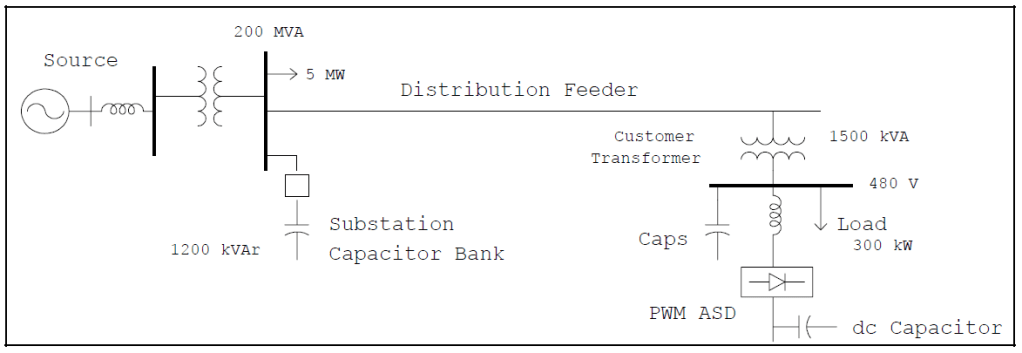
The oneline diagram shown in Figure 1 illustrates the system model used to investigate the nuisance tripping problem. The following parameters describe the system:
System Source Strength: 200 MVA
Switched Capacitor Size: 1200 kVAr
Step-down Transformer Size: 1500 kVA
Substation Load: 5 MW
480 Volt Load: 300 kW
Capacitor energizing operations, that cause a transient oscillation on the utility system, can cause an overvoltage trip condition on overly sensitive drives.
PWM ASD Characteristics
Pulse-width modulation (PWM) adjustable-speed drives (ASDs) typically have a voltage source inverter (VSI) type of design and use PWM inverters to supply the motor. Drives that use a voltage source inverter design are sensitive to utility capacitor switching transients due to the capacitor used in the dc link between the rectifier and inverter. The protection on the dc link capacitor is very sensitive to transient voltages on the ac power side. It is not uncommon for the dc overvoltage control to cause tripping of the drive whenever the dc voltage exceeds 1.2 per-unit (typical value). Figure 2 illustrates the ASD configuration.

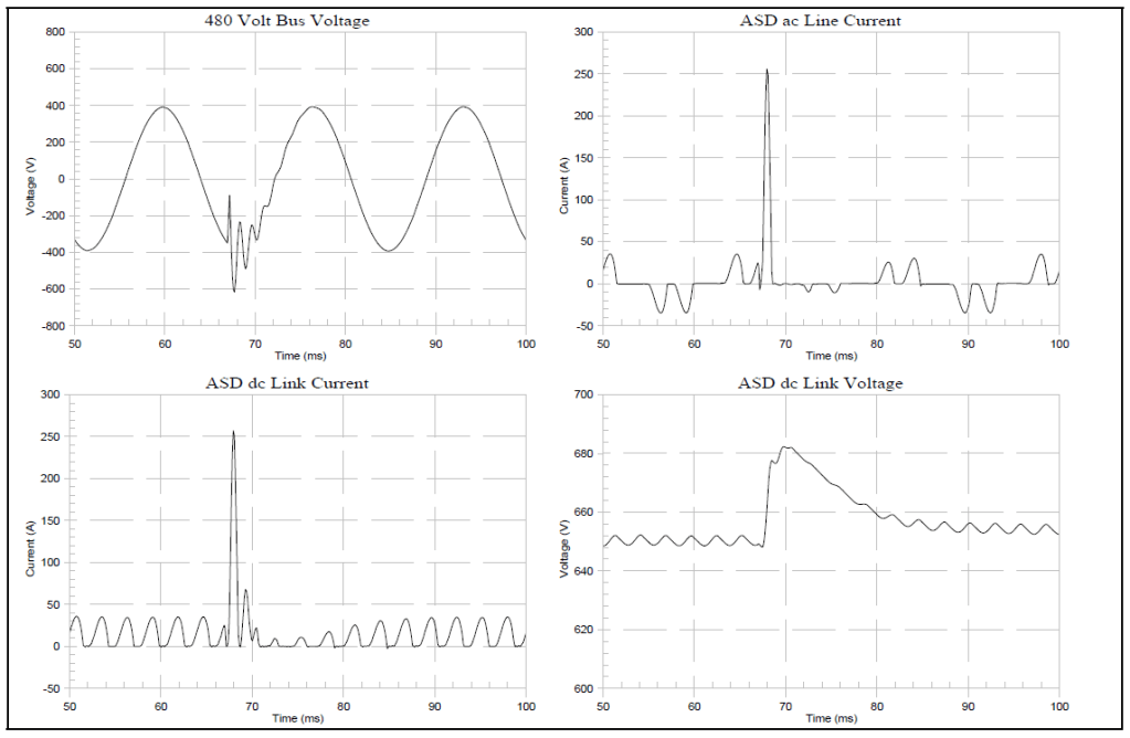
The potential for nuisance tripping is dependent primarily on the switched capacitor bank size (utility), the dc link capacitor size (ASD), and the inductance between the two capacitors. Figure 4.10 illustrates the transient overvoltages associated with energizing the 1200kVAr substation capacitor bank. Energizing transient overvoltages are generally not a concern for utilities because their magnitudes are usually below the protective level at which surge protective devices operate.
However, these transients can be magnified at the customer facility if the customer has power factor correction capacitors. Even if the customer does not have capacitors, the transient on the low voltage bus can cause a surge of current, at a relatively low frequency, into the dc link capacitor. The current surge charges the dc link capacitor and causes a overvoltage to occur. If this voltage exceeds the overvoltage trip setting, the drive will shut down. This is often refereed to as nuisance tripping because the situation can occur day after day, often at the same time. Figure 3 illustrates the dc current and voltage surge for this case.
The problem can be solved by adding an isolating inductance in series with the individual drives. This inductance can be in the form of a simple ac choke or an isolation transformer. Typically, a choke size of 3-5% is chosen. If the choke has too much impedance harmonic voltage distortion levels will increase (increased voltage drop due to harmonic current flowing through higher impedance). Figure 4 summarizes the impact of choke size on the dc overvoltage for a case where the switched capacitor bank (utility) was increased to 3000kVAr.

SUMMARY
PWM ASDs are susceptible to dc link overvoltage trips caused by utility capacitor switching. In general, an increase in input inductance (choke or isolation transformer) will reduce the possibility of nuisance tripping. However, if the customer has power factor correction capacitors on the same bus, it may be necessary to take additional remedial actions.
Additional actions may include configuring the power factor correction capacitors as harmonic filters. Power factor correction capacitors can create the potential for voltage magnification. This increased voltage transient can often be controlled using harmonic filters, thereby reducing the transient voltage to a level where the 3-5% choke is again effective.
An important point in this case is that the customer should not arbitrarily increase the choke size (above 5%) assuming it will continue to decrease the likelihood of nuisance tripping.
REFERENCES
G. Hensley, T. Singh, M. Samotyj, M. McGranaghan, and T. Grebe, Impact of Utility Switched Capacitors on Customer Systems Part II – Adjustable Speed Drive Concerns, IEEE Transactions PWRD, pp. 1623-1628, October, 1991.
G. Hensley, T. Singh, M. Samotyj, M. McGranaghan, and R. Zavadil, Impact of Utility Switched Capacitors on Customer Systems – Magnification at Low Voltage Capacitors, IEEE Transactions PWRD, pp. 862-868, April, 1992.
Electrotek Concepts, Inc., Evaluation of Distribution Capacitor Switching Concerns, Final Report, EPRI TR-107332, October 1997.
RELATED STANDARDS
IEEE Standard 1036-1992
GLOSSARY AND ACRONYMS
ASD: Adjustable-Speed Drive
PWM: Pulse Width Modulation
MOV: Metal Oxide Varistor
TVSS: Transient Voltage Surge Suppressors
