Published by Electrotek Concepts, Inc., PQSoft Case Study: PWM Drive Motor Failures due to Transient Voltages, Document ID: PQS0404, Date: June 30, 2004.
Abstract: In an effort to improve the efficiency of many industrial processes, equipment has been retrofitted with adjustable speed drives (ASDs). The ASDs allow for better speed control, soft starting of motors, and increased efficiency of the overall process operation. Unfortunately, there can be some drawbacks when using ASDs. While the effects of ASDs on the power system are well known, many engineers and system integrators are unaware of the effects that an ASD can have on the motor that it drives. This case study addresses one of the adverse affects; motor winding failure due to over voltages.
INTRODUCTION
In general, ac motor ASDs can be divided into two basic categories according to the working principle of the drive circuitry:
- Phase controlled front-end rectifiers, output current source inverter (CSI)
- Uncontrolled diode-bridge rectifier front-end, dc link, and voltage source inverter (VSI)
Until the late 1980’s, the inverters of large drives were Thyristor based with either forced-commutation or load-commutation. For CSI drives based on Thyristor or GTO devices, the inverter switching frequency was limited to several hundred Hz. This switching frequency implies that these devices have relatively high commutation losses and need a relatively long commutation period. Consequently, motors supplied by CSI drives will have less chance of seeing fast-front voltages and therefore, are not discussed.
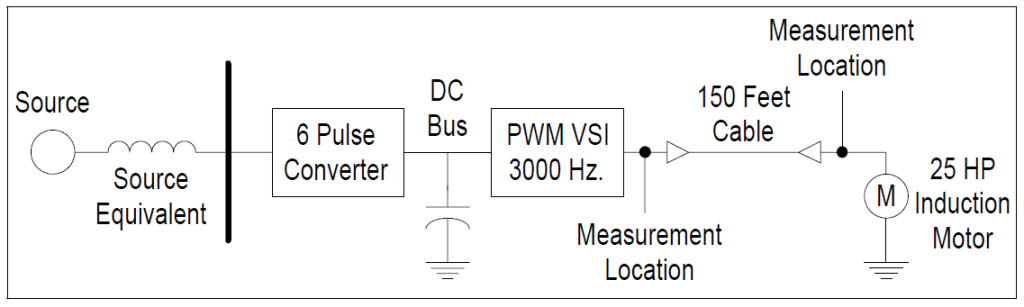
Drives for most small and medium sized induction motors may utilize voltage source inverters (VSI) to provide variable frequency ac output. The common drive structure adopted by industry consists of an uncontrolled diode-bridge rectifier, dc link, and PWM VSI inverter as shown in Figure 1. The dc link for the VSI type drive is basically a ripple smoothing capacitor. The inverter output waveform is generated by a series of step-like functions. Stray parameters of the circuit and commutation of switching devices from one phase to another prevent an ideal step-change in the output voltage. Steep-front waveform generation is one of the inherent characteristics of a high frequency operation voltage source inverter.
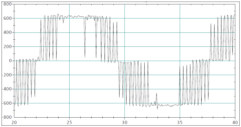
Both frequency and magnitude of the output voltage are adjusted by controlling the inverter’s operation. State of the art VSIs are based on IGBT technology. With IGBT devices, the inverter operates with a switching frequency ranging from tens of Hz to tens of thousands of Hz. Figure 2 illustrates the typical output voltage of a PWM drive. The switching frequency of the most commonly used PWM drives is in the range of 1000 Hz to 5000 Hz. The rise times of the pulses for IGBT VSIs can be on the order of 10μs to 0.1μs.
THE PROBLEM
The problem occurs on the output of the ASD at the drive terminals. The high switching frequency of IGBTs allows sophisticated PWM schemes to be implemented. One of the advantages of the high switching frequency inverter is the reduction of low order harmonics, which results in the reduction of the output filter requirements. However, this benefit can only be achieved under certain circuit conditions. Under some particular conditions, the fast changing voltage resulting from high frequency switching operation of IGBT VSIs can create severe insulation problems for an induction motor.
Machine insulation integrity is affected by the rate of change of voltage as well as the over voltage magnitude. A voltage with a high rate of change tends to be distributed along a motor’s winding unevenly. This uneven distribution causes a significant over-stress across ending turns resulting in turn-to-turn insulation failure. In practice, it is common for the drive and the motor to be separated by long lengths of cable. Usually, the characteristic impedance of the motor can be ten to one hundred times that of the characteristic impedance of the cable connecting the drive to the motor.
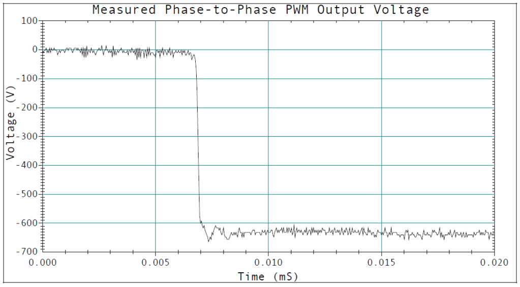
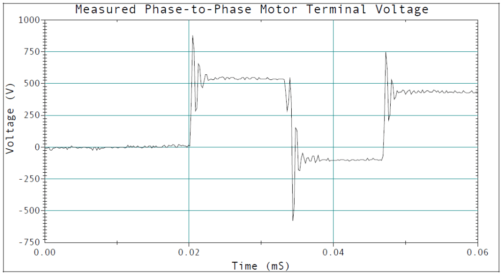
The most harmful effect of the PWM ASD output occurs when the connection cable is relatively long with respect to the wave front of an incidental voltage wave and when the ratio of characteristic impedance of the machine and the cable is high. In the worst case, an inverter output voltage pulse magnitude can be doubled at the induction motor terminals. Figure 3 illustrates one pulse transition as measured at the output of the ASD. Figure 4 illustrates several pulse transitions as measured at the terminals of an induction motor being supplied by an ASD. Notice the overshoot at the beginning and end of each pulse.
THE SOLUTION
There are many potential mitigation techniques which might be employed to solve the over voltage problem at the motor terminals. With the proven EMTP simulation model, effectiveness of two promising solution methods were explored. These two methods are:
- Install a line choke, in series with the connection cable, on the output of the PWM drive.
- Install a capacitor, in parallel with the motor, at the motor terminals.
To evaluate the choke solution, a 5% (on the base of the 25 hp motor) inductor was inserted between the drive output and the connecting cable at the drive output terminals. The resulting phase-to-phase voltages at the drive output terminals and at the motor terminals are plotted together in. This ac output choke failed to control motor terminal over voltage as illustrated in Figure 5.
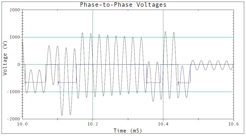
The choke inductance did help to reduce the rate of change of the voltage seen by the motor. However, the choke created an extra circuit mesh which formed its current loop through the inverter source, choke inductance and cable equivalent capacitance.
The idea of installing capacitance at the motor terminal is initially drawn from the concept of matching the cable surge impedance with the characteristic impedance seen at the motor terminals. However, a precise matching of the impedance may require an amount of capacitance which is undesired for overall system consideration. Therefore, a compromise solution is to add some amount of capacitance to reduce the motor terminal characteristic impedance, and to introduce the proper level of damping to control the voltage overshoot. Based on this concept, three basic damping circuits can be used. They are:
- An over damped circuit
- A critically damped circuit
- An under damped circuit
Each circuit includes a resistance in series with a capacitor. This series combination will be in parallel with the motor’s windings. The EMTP simulations showed that the best results were obtained when a critically damped circuit was employed at a properly selected resonant frequency. This method assures that the pulse at the end of the cable more closely matches the pulse at the beginning of the cable.
Knowing the switching frequency of the PWM drive was 3000 Hz and based on practical experience, it was decided that a good resonant frequency for the damping circuit would be five times the switching frequency or 15,000 Hz. Using the inductance of the cable (0.027mH for 150 ft. of # 8 AWG) the value of the capacitance was calculated to be 4.2μF and the damping resistance was selected to be 5.5 ohms. This circuit’s damping resistance was calculated based on 15,000 Hz.
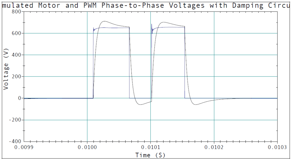
Figure 6 illustrates the effect that the introduced RC circuit has on the voltage at the motor terminals. The negligible over shoot in the voltage waveform illustrates that the circuit is slightly under damped. However, this approach does seem to have some merit. The high voltage reflection at the motor terminals is well under control and the over voltage is less than 1.2 per-unit. But, even more importantly, the steep front of the voltage pulse has been greatly reduced.
SUMMARY
When retrofitting induction motors with PWM ASDs, care must be taken in the length of the cable feeding the motor. Cases have been reported where a cable length as short as fifty feet caused a transients problem at the motor terminals. Conversely, there have been cases where the cable length was over 200 feet without adverse effects. If the problem is detected, an effective solution is to parallel an RC branch right at the motor terminals. Parameter selection for this RC branch is based on the drive circuit information and should be determined on case-by-case basis.
ASD manufacturers are now working with motor manufacturers to match drive duty motors to their drives. The ASD and motor come as a complete package. In fact, some motor manufacturers will not honor warranties for motors that are driven by PWM ASDs. And, in the case of new installations, require that the drive and motor be purchased as a package. The induction motors are designed to withstand the severe duties imposed on them by the high switching frequencies of the PWM drives.
REFERENCES
[1] Melhorn, C. J., Le Tang, “Transient Effects of PWM Drives on Induction Motors,” IEEE Transactions on Industry Applications, Volume 33, Number 4, July/August 1997.
[2] Persson, E., “Transient effects in application of PWM inverters to induction motors,” presented at the IEEE/IAS 1991 Pulp and Paper Industry Conf., Montreal, P.Q., Canada, June 3-7, 1991, Paper PID 91-28.
GLOSSARY AND ACRONYMS
ASD: Adjustable-Speed Drive
PWM: Pulse Width Modulation
VSI: Voltage Source Inverter
