Published by Alena OTCENASOVA, Juraj ALTUS, Petr HECKO, Marek ROCH,
Slovakia, University of Zilina, Faculty of Electrical Engineering, Department of Power Electrical Systems
Abstract. Worsened quality of supplied as well as demanded electricity causes in reality a large financial loss. The main quality parameters monitored today are voltage dips and interruptions. In this context there are relevant statistics of measurement results and especially the possibility of their improvement by using Dynamic Voltage Restorer, for which we have proposed a possible method of control. The proposed regulation DVR is based on Park transformation of immediate values of voltage in network and its feedback transformation. The method is shown and verified on simulation model.
Streszczenie. Pogorszenie jakości dostarczanej jak również zapotrzebowanej energii elektrycznej powoduje powstawanie dużych strat finansowych. Podstawowymi parametrami jakościowymi monitorowanymi obecnie są spadki napięcia i przerwy w zasilaniu. W tym kontekście istnieją adekwatn statystyki pomiarowe, a w szczególności możliwości ich poprawy poprzez użycie dynamicznego układu odtwarzania napięcia (DVR), dla którego zaproponowaliśmy metodę sterowania. Proponowana metoda sterowania układem DVR bazuje na transformacji Parka wartości chwilowych napięcia w sieci i ich transformacji odwrotnej. Metoda została przedstawiona i zweryfikowana na modelu symulacyjnym. (Pomiary parametrów napięcia w praktyce i możliwości poprawy jakości napięcia)
Keywords: power quality, electrical network, voltage dips and interruptions, dynamic voltage restorer, controlling of DVR.
Słowa kluczowe: jakość energii, sieć elektryczna, spadki napięcia i przerwy w zasilaniu, dynamiczny układ odtwarzania napięcia, sterowanie układem DVR.
Introduction
Problems with power quality are always hot topic. The quality of electricity is influenced by many factors and to keep the parameters within the required limits is in many cases difficult. Worsened quality of electricity is often caused by customers by the nature of theirs operation. As they are in many cases supplied together with other customers from the point of common coupling it can lead to a situation where one customer’s device may retroactively influence also other customers. Likewise, negative influences can come from a distribution and from the transmission system too.
Study [1] focused on the problems with power quality prepared by the David Chapman from the Copper Development Association confirms that supplied electricity, whose quality does not satisfy relevant standards, causes huge economic losses. During resolving study David Chapman calculated concrete values of losses and says that the problems with power quality cost industry and business in the European Union around 10 billion euro per year.
Quality parameters of voltage
In general, power quality is evaluated according to the quality of electrical voltage. Basic characteristics of the quality parameters are given in the STN EN 50160 „Voltage characteristics of electricity supplied from the public distribution networks” [2]. This standard applies to low and medium voltage supply and is generally valid. It is applicable to electricity networks in European industrial areas, as well as the electricity network supplying the „two families isolated in the desert”.
This leads to various quality requirements. For many customers is the quality of voltage low even if it satisfies the requirements for quality according to STN EN 50160 and electricity is unusable (for example, the frequency of interruptions and voltage drops). Therefore stricter standards exist, for example STN EN 61000-2-2 and STN EN 61000-2-4 [3]. It is important that the customer has agreed properties of energy supplied according to the standards that match the type of operation with suppliers of electricity.
Standards that characterize quality parameters of electricity and specify the limits of parameters serve to ensure the functionality of devices supplied from this network, as well as devices that are connected to the network later [4].
Problems with quality of electricity in operating practice
Power Grid Company [5] deals mainly with power quality measurement, delivery devices that increase the quality of electricity supply and distribution activities of components that are necessary for the production of compensation units, of low power electronics and semiconductors. Fig. 1 shows the statistical processing of various problems in industrial networks. These data are measurement results done by Power Grid Company [5] mainly in Slovakia and minor share in the Czech Republic.

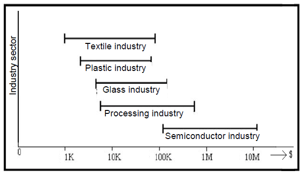
From the qualitative parameters listed in Fig. 1 dips and interruptions of supply voltage cause the highest economic losses [6]. Voltage dips and interruptions are especially dangerous for a group of customers, which are called the sensitive customers. For these customers even short time voltage dip may have the same economic impact as a long-term interruption of power supply. Examples of industries that are the most sensitive to the quality of power supply, including the costs to be paid on one fault (in dollars), are shown
in Fig. 2 [6].
Dips (sags) and interruptions of voltage
Sags and interruptions belong among the quality attributes that can be easily identified by today’s network analysers. However solving problems is difficult, especially financially. As this can cause failure, damage to engine and also equipment, which results in considerable financial losses, increased attention is devoted to solving related issues. Their occurrence and frequency is random and are usually caused by external factors (weather, animals, vegetation, traffic accidents …). Statistics of interruptions and voltage drops of voltage (Fig.3) shows that in case of electricity the largest group is voltage dips from 10 to 30 % with duration from 10 to 100 ms.

In the operation, that deals with production cable harnesses for cars (cutting machine, foaming machine, ultrasonic welder, transporters, lighting, air conditioning, heating) there have been taken comparative measurements of power quality of network on 22 kV and 400 V sides of transformer in the substation MV on shorting terminal for invoice measurement.
At the same time short-term measurements were performed on the electronic board of the individual machines – foaming machine, ultrasonic welding, UPS, cutting machine. The problems presented by the client: power interruptions of electricity supply network – both short and long, voltage dips in the network – the consequent failure of production facilities. More dips, but also interruption in the L3 phase was recorded (Fig. 4) during network analysis.
The measurement was made simultaneously on the LV system and MV system, and therefore dips to low and middle voltage side can be compared. Comparison shows that dips and interruptions on LV side are always caused by dips and interruptions in the MV system.
Power Grid Company offers to solve the problem by installation of “Active voltage conditioner (AVC)”. AVC can eliminate a few seconds duration voltage sags and interruptions by defined way. The company offers several different AVC, which correspond to the different requirements for electric power.

AVC parameters are based on customer’s requirements on elimination of the dip length and its level and of course on desired power. The price of the equipment is highly dependent on AVC specifications. There is a possibility of AVC installation, which eliminates voltage failure for example 30 s for power several MV.A. Another possibility is for example use of industrial uninterruptible power supplies (UPS) where price is considerably higher.
The company can install UPS to machines that are most sensitive to power disturbances and therefore cause maximum economic damage. Another possibility is to supply the company from another power line which will supply company by energy in the case of primary source failure.
Another option, which will be discussed in the next part, is to compensate voltages dips and interruptions by Dynamic Voltage Restorer (DVR).
The principle of operation the DVR
Development of such compensation devices is connected with the development of power semiconductor devices. Basic connection of the DVR is in Fig. 5.

The DVR is connected in series between the supply network and sensitive load. The voltage dips compensator is composed of single direct energy storage device, inverter, control circuit and a serial transformer. If the voltage dip appears on the supply side, the DVR will respond to this decline, and injects voltage into the network, which is needed to compensate accrued voltage dip. The result of this process is then constant voltage amplitude, which is to terminals of sensitive customer [6].
DVR control algorithms
The most important part in terms of proper function of the DVR is the correct control algorithm. The main function of the control algorithm is to keep required voltage value of sensitive loads in case of failure. Means of proceedings of real applied voltage compensators are “Know – how” of companies that install these devices. Various institutions such as universities, research institutes and specialized companies they are still exploring and testing new voltage compensators control algorithms. In general, it is difficult to design control algorithm, which could be generally applied and would also accept the economic aspects. Therefore, there are several control methods, and their application should be considered individually for each specific project.
There are several basic methods that are used in the control of compensators for dips and interruptions. These are the methods Pre-sag, In-phase and the newest method of Minimal Energy Control (controlling for the minimum energy) [7].
Model DVR based on the Park transformation
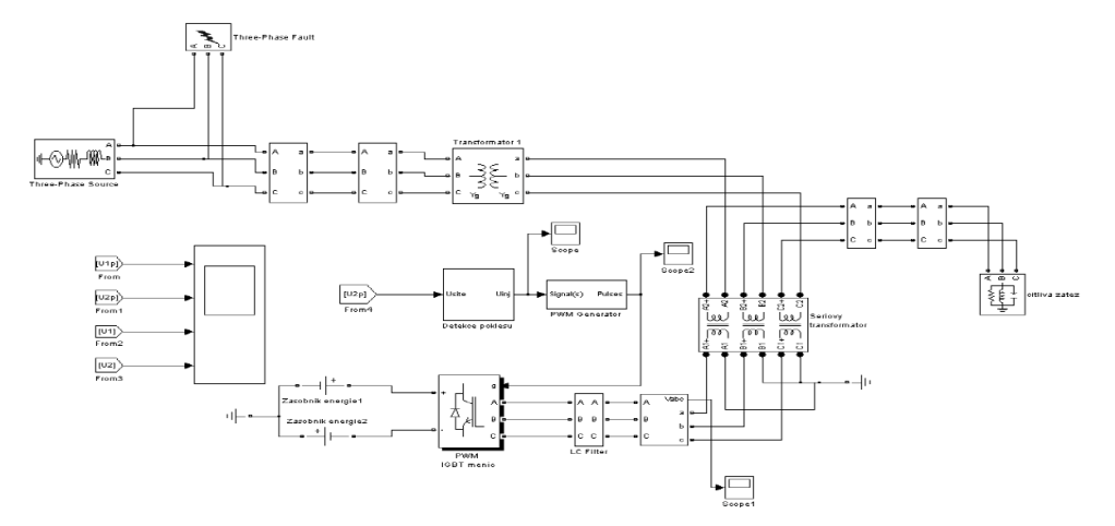
In terms of solving the problem of voltage dips, we have proposed a model DVR (Fig. 7). The control algorithm is based on the Park transformation.
Park’s transformation is the transformation connected with the rotor axis in theory of machines. It is also known as the transformation from abc, respectively αβ to dq0 components. Graphical presentation of Park transformation is shown in Fig. 6 [9].
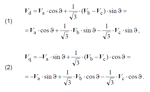
Park’s transformation is derived from the equations of Clarke transformation. When we derive equations as a base we use the equations for the calculation general stator variable [9]. Equations (1) and (2) represent mathematical description of the Park transformation:
The inverse Park’s transformation can be expressed by a similar procedure. For actual utilization in this paper there are presented only the final equations of the inverse Park transformation (6), (7) and (8).
Equations of Clarke and Park transformation are presented in different literatures in different modifications, while the principle remains the same. Simulation program Matlab/Simulink, which is used to simulate control DVR, calculates Park transformation using equations (3), (4) and (5):
Inverse (return) Park transformation is in MatLab described by equations (6), (7) and (8):
These equations are implemented into transformation blocks in Matlab/Simulink and are verified using computer simulations in the following part of article.
The principle of model operation DVR
The voltage that is measured in per units at the terminals appliance is transformed into dq0 components. We follow the theory that if the three-phase system is symmetrical, zero or q component does not develop after the Park transformation. If there is the asymmetry (for example the voltage dips in one phase) q component develops as well as the zero component. We compare this transformed value of voltage on appliance with dq0 constants, which represents a symmetrical system. If deviation occurs, the PI controllers regulate the deviation to zero. Then Park’s transformation is applied retroactively, and the resulting voltage is supplied into the PWM generator, which then sends impulses to the inverter, which creates the required voltage. Energy storage supplies inverter by power and it is created by direct ideal source. This voltage is then filtered by LC filter and through serial transformer injected into the network.
Verification of functions of the model DVR
To check correct DVR functioning there were simulated different disturbances and the response of monitored DVR. The DVR is designed and tested on the level of 22 kV, where it is normally installed.
For example, we present DVR reaction on the interphase short circuit that was simulated on the 110 kV voltage level at the time from 0.1 to 0.2 s. The resulting waveforms are shown in Fig. 8 and Fig. 9. In Fig. 8 is the voltage waveform displayed before DVR and the voltage waveform on the terminals of appliance is on the Fig. 9.


From the measured curves we can see that the customer has on its terminal constant value of voltage even if voltage failure occurs in the power supply network. It shows that DVR model fulfills its primary function and the proposed control algorithm works as we require from him.
Conclusion
In the article are described some results of measurements of the quality parameters of electricity with focus on voltage sags and interruptions. These disturbances cause significant financial losses for manufacturing companies. Therefore, there have been described ways how to prevent financial losses.
One of such methods is to install the Dynamic Voltage Restorer, which is closer specified in the article. The function of this voltage compensator has been verified by computer simulation and results confirm its proper operation. Installing the DVR is only theoretical with respect to its purchase price and the final choice of appropriate compensation is on the managers of the company.
Acknowledgment
This work was supported by European regional development fund (ERDF), name of project: Centre of excellence of power electronics systems and materials for their components, No.: OPVaV-2008/2.1/01-SORO, ITMS 26220120003.
REFERENCES
[1] Chapman, D., The cost of poor power quality. Power quality application guide. London, UK, 2001
[2] STN EN 50160 (33 0121). 2011. Voltage characteristics of electricity supplied by public electricity networks
[3] STN EN 61000-2-4 (33 3432). 2003. Electromagnetic compatibility (EMC). Part 2-4: Environment – Compatibility levels in industrial plants for low-frequency conducted disturbances
[4] Altus, J.,Novák, M.; Otčenášová, A.; Pokorný , M. , Electromagnetic compatibility of power systems, EDIS, publisher University of Zilina, SK, 2004, ISBN 80-8070-227-6
[5] http://www.power-grid.eu, + database Power Grid Company
[6] Kuo, Y. Z.: Dynamic voltage restorer for sensitive equipment. Arlington, Texas. Dissertation thesis, 2007
[7] Dobrucký, B., Šul, R., Špánik, P., Zabezpečenie napájania kontinuálnych procesov s využitím zariadení FACTS. AT&P journal, Nov. 2005, pp. 79-81.
[8] Hečko P. , Compensation voltage dips and interruptions in power station 110/25 kV, Žilina, Slovakia, Dissertation thesis, 2010
[9] Š t ěpina, J., Souměrné složky v teorii točivých elektrických strojů. Academia, Praha, 1969
Authors: prof. Ing. Juraj Altus, PhD., University of Zilina, Faculty of Electrical Engineering, Department of Power Electrical Systems, Univerzitná 1, 010 26 Žilina, Slovakia, E-mail: Juraj.Altus@fel.uniza.sk; doc. Ing. Alena Otčenášová, PhD., University of Zilina, Department of Power Electrical Systems, Alena.Otcenasova@fel.uniza.sk; Ing. Petr Hečko, E-mail: petrhecko@gmail.com.
Source & Publisher Item Identifier: PRZEGLĄD ELEKTROTECHNICZNY (Electrical Review), ISSN 0033-2097, R. 88 NR 9a/2012
