Published by Szymon PIASECKI1, Marek JASIŃSKI1, Krzysztof RAFAŁ1, Marek KORZENIEWSKI 2, Aritz MILICUA3, Politechnika Warszawska, Instytut Sterowania i Elektroniki Przemysłowej (1), Politechnika Białostocka, Katedra Energoelektroniki i Napędów Elektrycznych (2), Uniwersytet w Mondragon, Wydział Elektryczny (3)
Abstract. The paper presents overview of high-order harmonics compensation methods applied for control of grid-connected converter. Two harmonic compensation methods are presented. One based on band-pass filers cooperating with Direct Power Control with Space Vector Modulation (DPC-SVM) is dedicated for renewable energy interface. Second method based on resonant controllers applied in Voltage Oriented Control (VOC) adds an active filtering function to PWM rectifier. Simulation and preliminary experimental results for these two methods are presented.
Streszczenie. Artykuł prezentuje wybrane metody kompensacji wyższych harmonicznych. Pierwszą bazującą na filtrach cyfrowych przedstawiono w aplikacji, w bezpośrednim sterowaniu mocy z modulacją wektorową (DPC-SVM) przekształtnikiem sieciowym. Drugą bazującą na regulatorach rezonansowych przedstawiono w sterowaniu napięciowo zorientowanym (VOC) jako funkcję aktywnej filtracji sterowanego prostownika sieciowego. Na zakończenie przedstawiono wstępne wyniki badań symulacyjnych i eksperymentalnych. (Kompensacja wyższych harmonicznych w sieciowym przekształtniku PWM)
Keywords: grid-connected converter, harmonic distortion, harmonic compensation, power quality, active filters
Słowa kluczowe: przekształtnik sieciowy, odkształcenie wyższymi harmonicznymi, kompensacja harmonicznych, jakość energii, filtry aktywne
Introduction
Nowadays there are many issues closed in the general term “Power Quality”. Electrical networks become larger every year, a huge number of different electrical devices fulfilling different standards are being connected to the grid. Equipment becomes more advanced, complicated and in fact more sensitive to quality of power supply. On the other hand, loads connected to the common network contain a lot of power electronic devices like power switches, UPS systems etc. – they can work with higher efficiency and speed, but also generate disturbances (higher harmonics). Fifteen years ago voltage distortion by high-order harmonics was marginal and almost unknown phenomenon for ordinary customers. Now it becomes very serious problem. Because number of nonlinear loads is growing, the line distortion by high order harmonics is constantly growing. High order harmonic distortion generates losses, causes overheating of many electrical devices and cuts down their predicted operation time even on 75%. Also it generates standstills and this increases costs. Therefore there is a growing interest in methods to compensate for higher harmonics
The following sections describe problem of higher harmonics compensation in PWM grid-connected converters. A brief description of power quality standards in context of higher harmonics compensation is given. Two methods dedicated for different applications are presented. Also, simulation models and results are presented. Finally two experimental setups are described and experimental verification results are given.

Power Quality Standards in context of harmonic distortion
Basic standard which defines quality of electrical energy is European Standard 50160 set in 1994. This standard describes electrical energy as a product and gives main characteristics of the voltage in public low-voltage and medium-voltage networks under normal operating conditions. Main characteristic of voltage harmonic distortion at the customer’s supply terminals are as follows – for harmonic distortion voltage components up to order 25, specific values are given which shall not be exceeded during 95% of the 10-minute average obtained in one week. The THD (Total Harmonic Distortion) factor shall not exceed 8% during 95% of the week [1].
Other important standards which describe power quality are: IEEE Standards, like IEEE 519-1992, IEEE SCC-22: Power Quality Standards Coordinating Committee, IEEE 1159: Monitoring Electric Power Quality etc. and General IEC power quality standards, like IEC 61000-4-11, IEC 61000-4-34 or IEC 61000-4-30.
Power Quality in Grid-Connected Converters
There are two major applications of grid-connected converters:
- in electrical drives (Fig. 1a).
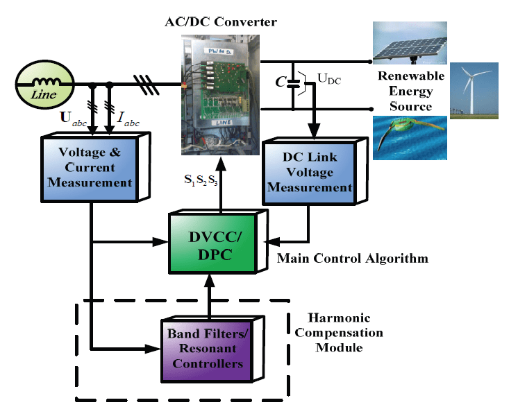
- as interface for renewable energy source (Fig. 1b).
Most of conventional rectifiers are based on diode and thyristor bridges, being source of harmonic distortion. Most serious of generated harmonics are 5th, 7th, 11th and 13th. Conventional compensation method is installation of passive filters based on LC elements tuned to particular frequency. This method is relatively easy to implement, however, there are few disadvantages as problems with resonance, size and price of passive elements, dependency on temperature and frequency, etc. To avoid these problems a power electronic solution – active filter have been developed. It includes grid-connected PWM converter, injecting only higher harmonic current compensating the load current. In this way current drawn from the grid remains sinusoidal. This function can be included not only in the active filters, but also in STATCOM devices or modern electrical drives based on PWM rectifiers [2].
Grid interfacing converters are also influenced by supply voltage quality. Conventional control algorithms are designed to operate with pure sinusoidal voltage, higher harmonics in voltage usually cause distortion of current injected to the grid. This is of great importance, particularly in converters interfacing renewable energy sources. Most of European countries with high penetration of renewable energy have their own standards concerning quality of power injected to the grid by renewable sources, called “grid codes” [3], [4]. Imposed harmonic limits are usually much more strict than ES50160 limits.
Proposed Harmonic Compensation Methods
Conventional control methods like VOC and DPC-SVM are designed to control only fundamental component of current. For higher harmonics compensation additional control loops have to be introduced, as shown in Fig. 2. Higher-order harmonics compensation block is a module of main control algorithm. It can be optionally used and modified. Among another methods proposed in literature, two most interesting were chosen and studied [5].
First includes band-pass filters based method in multiple rotating reference frames. This method has been applied to compensate influence of higher harmonics on grid interfacing converter based on DPC-SVM control.
Second examined method uses resonant controllers to include active filter functionality to PWM converter. Cooperating with Dual Vector Current Control it can compensate for higher harmonics and asymmetry of other loads.
Direct Power Control with Space Vector Modulation and Harmonic Compensation
In Fig. 3 the block diagram of DPC-SVM (Direct Power Control with Space Vector Modulation) is presented. DPCSVM is a control algorithm mostly used in applications of converters which need bi-directional energy flow, like Renewable Energy Sources or bi-directional power flow drives. This method gives very good dynamic and static performance. Used Space Vector Modulator assure constant switching frequency and reduce switching loses. Active and reactive power are used as control variables instead of the line currents controlled in VOC scheme. Active and reactive power is controlled in close-loop using PI controller. Outer control loop with additional PI controller is DC-link voltage control loop. This solution gives possibility to manually set reference DC-link voltage. Output of this control loop multiplied by DC-link voltage module is a reference for an active power controller. Reactive power reference is set to 0. However, it should be pointed that in RES referenced reactive power should be controlled in respect to the line voltage quality improvements. To achieve synchronization of generated energy with the grid, even when supplying voltage is distorted Phase Locked Loop (PLL) control algorithm was used.

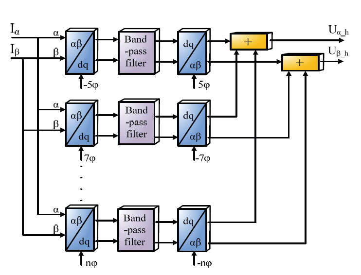
To improve control algorithm active filter based on bandpass filters was implemented. Block diagram of this method is presented in Fig. 4. In this method measured currents are transformed into multiple rotating reference. Reference frames rotate synchronously with multiplication of grid voltage (5th, 7th etc.). Each frame is dedicated for one harmonic which will be compensated. In this case 5th and 7th harmonics are compensated. Each high-order harmonic is filtered out by band-pass filter. The filtered current waveforms give information about considered higher harmonics amplitudes. After filtration process signals are again transformed into stationary reference frame and summed up. Output signals from Harmonic Compensator are added to the main reference voltages for SVM.
Dual Vector Current Controller with Active Filtering
Second investigated control algorithm of the grid-connected converter is based on modified VOC algorithm, namely Dual Vector Current Controller [6]. Block diagram of this method is presented in Fig. 5. In this control method positive and negative sequence of the line current are controlled separately.
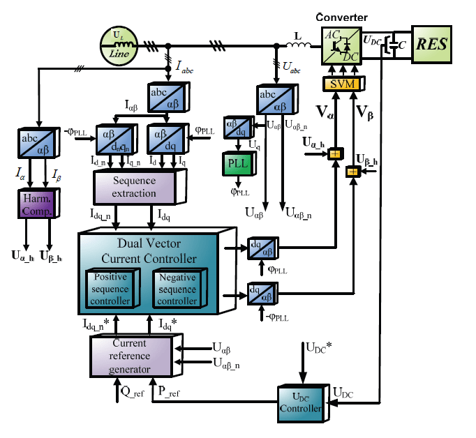
This solution gives very good dynamic and stable operation of the system during asymmetrical grid voltage. Current references are calculated based on power references [2], [8] – active power, which is given by DC Link controller and reactive power which is set manually, this gives possibility for the system to work as a reactive power compensator. Here also to synchronize with line voltage Phase Locked Loop algorithm was employed.
For this control algorithm active filter based on resonant PI controllers was implemented. This solution is presented in Fig. 6. After high-pass filtration actual grid current is transformed into Synchronous Reference Frame. After transformations 5th and 7th harmonics become 6th harmonic component and both can be compensated by single controller, which makes this method very efficient.

Resonant controller is a second order transfer function designed to have very high gain at particular frequency. In presented system two controllers were implemented at 300Hz and 600Hz, compensating for most dangerous harmonics generated by diode and thyristor rectifiers.
Simulation model
Proposed control structures were implemented and checked in simulation studies. Simulation models were build in Synopsys Saber and Matlab Simulink packages. Saber is a multi-domain modeling and simulation environment with very advanced libraries and background for power electronic systems. In used simulation model basic control algorithm was implemented in Mast programming language which is programming tool in this simulation package. Model contains following subsystems: line model, which gives possibility to create distortions like dips or high-order harmonics, converter model, measurements system model, DC-link load model and finally control block model [7], [9]. Dual Vector Current Controller with digital harmonic filtration based on resonant controllers simulation model was created in Matlab Simulink. Matlab Simulink is nowadays one of the most popular used simulation and computation software which also has very strong backward for power electronics simulations. Base simulation model was created using Simulink platform with standard power electronics elements. Model contains following subsystems: line (grid) model, main DVCC control algorithm, coordinate systems transformations blocks, power system and Phased Locked Loop algorithm.
Simulation results
In this subsection selected simulation results are presented. First part presents results for digital filter module based on band-pass filters with DPC-SVM control method.
a) Band-pass filters in DPC-SVM algorithm

Fig. 7 presents line voltage distorted by 10% of 5th harmonic. Result of this distortion for operation of the converter is shown in Fig. 8, where line currents during standard operation of the converter without any compensation algorithm.

Fig. 9 presents the same conditions (voltage distorted by 10% of 5th harmonic) but with harmonic compensation algorithm. It can be observed that current harmonic content is significantly reduced.

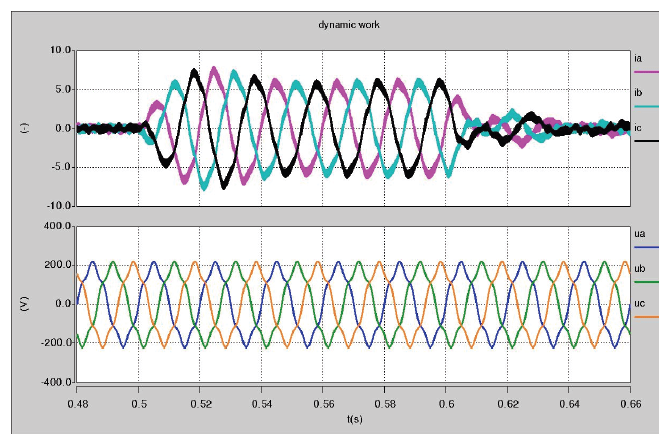
Fig. 10 presents dynamic state during step change of the load under distorted line voltage (10% of 5th harmonic), harmonic distortion is meaningly compensated. This results present good dynamic and stability of digital filter based on band-pass filters.
b) Resonant controllers
In this part simulation results for active filter based on resonant PI controllers with DVCC control method are presented. In Fig. 11 steady-state of the harmonic compensator is presented.


In this case a diode-bridge rectifier which generates harmonic distortion with 5th, 7th, 11th and 13th harmonics is connected to the Point of Common Coupling (PCC). Despite of voltage distortion currents are sinusoidal, high-order harmonics are compensated.
Fig. 12 presents currents during step change of the load for the same conditions as presented above (voltage distorted by 5th, 7th, 11th and 13th harmonics).
This preliminary simulation results show possibilities of proposed control structures to compensation of higher-order harmonic distortion. Both control strategies give satisfactory simulation results and both will be studied and developed in further research. All simulation tests have been verified by experimental tests.
Laboratory setup
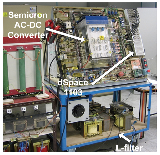
For experimental verification two experimental platform were used. DVCC with digital implemented filter module based on resonant controllers was implemented on test bench in University of Mondragon, Spain Fig.13 presents experimental platform for DVCC tests. This setup consist of: serially produced Semicron’s AC-DC converter and DSP/RISC dSpace 1103 card. To generate grid voltage disturbances Chroma Progrmmable AC Source was used.

DPC-SVM with digital filter module based on band-pass filter was implemented in test bench which was built in Warsaw University of Technology. Experimental platform is shown in Fig. 14. To generate grid voltage disturbances California Instruments iX Series programmable AC voltage source was used. Experimental platform contains following elements: PC with dSpace 1103 card, dSpace connector panel, 2 pairs of industrial AC-DC-AC converters (2x Danfoss 5 kW and 2x Twerd 7.5 kW), L-filter, current and voltage measurements, isolation transformer. Some preliminary experimental results are presented below.
Experimental results
In this part preliminary experimental results are presented. In Fig. 15 line currents during stable operation of the AC-DC line side converter with DPC-SVM control algorithm. Supplying line voltage is distorted by 10% of 5th harmonic, currents generated by the converter are distorted.

In Fig. 16 functionality of an digital filter module based on resonant PI controllers are presented. Line voltage is distorted by 5th, 7th, 11th and 13th harmonics generated by diode-bridge rectifier connected to the grid. Fig. 16 presents grid current waveforms and its spectrum without and with digital filter module compensated.
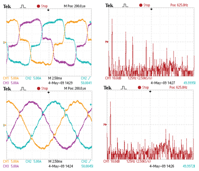
Results show ability of the filter to compensate high-order harmonics, current waveforms are sinusoidal and THD is decreased.
Fig 17 presents behavior of an digital filter module during step change of the load, grid voltage distortion is the same like in example above. Also in this case digital filter module is able to compensate high-order harmonics generated by non linear load.
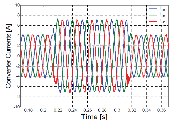
Table 1. Experimental platform parameters.

Summary and Conclusions
This paper presents two different solutions for digital filter modules. Both of them give active filtering functionality of line-side AC-DC converter. In presented solution digital filter module is a optional functionality implemented in two different control methods for line side converter – DPC-SVM (Direct Power Control with Space Vector Modulation) and DVCC (Dual Vector Current Controller). Both presented strategies give satisfactory results, higher-order harmonic distortions are significantly compensated. These applications are dedicated for Renewable Energy Sources (RES) and will be developed and tested in focus on RES power quality improvements. However, it is necessary to increase functionality of laboratory setup in focus on research with efficiency and robustness improvements.
This work was partly supported by the National Center for Research and Development, Poland, developing grant no. N R01 0014 06/2009.
This work has been partly supported by the European Union in the framework of European Social Fund through the Warsaw University of Technology Development Programme, realized by Center for Advanced Studies.
REFERENCES
[1] PN-EN 50160 ” Parametry napięcia zasilającego w publicznych sieciach rozdzielczych.”
[2] M. P. Kaźmierkowski, M. Jasinski, Hans Ch. Sorensen , „Ocean Waves Energy Converter – Wave Dragon MW”, Przegląd Elektrotechniczny, ISSN 0033-2097, r. 84 Nr 2/2008, str. 8-13.
[3] V. Ajodhia, B. Franken „Regulation of Voltage Quality” Kema Consulting
[4] Rozporządzenie ministra gospodarki z dnia 4 maja 2007 r.” W sprawie szczegółowych warunków funkcjonowania systemu elektroenergetycznego”
[5] S. Piasecki, M. Jasinski, A. Milicua, „Brief view on Control of Grid-Interfacing AC-DC-AC Converter and Active Filter under Unbalanced and Distorted Voltage Conditions”, International Journal for Computation and Mathematics in Electrical and Electronic Engineering (COMPEL) on EVER’09, Emerald, in volume 30, no. 1, 2011, pp. 351-373.
[6] Milicua A. , Piaseck i S., Bobrowska M., Rafał K., Abad G., Coordinated Control for Grid Connected Power Electronic Converters Under the Presence of Voltage Dips and Harmonics, EPE Conference 2009
[7] H. Song, K. Nam, “Dual current control scheme for PWM converter under unbalanced input voltage conditions”, IEEE Transactions on Industrial Electronics, Vol. 46, No.5, October 1999, p.953-959
[8] Kazmierkowski M.P., Krishnan R., Blaabjerg F., “Control in Power Electronics Selected Problems,” Academic Press, 2002.
[9] Song H. S., Nam K., “Dual current control scheme for PWM converter under unbalanced input voltage conditions”. IEEE Trans. Indus. Elect, Vol. 46, No. 5, pp. 953-959, Oct. 1999.
Autorzy: mgr inż. Szymon Piasecki, dr inż. Marek Jasiński, mgr inż. Krzysztof Rafał Politechnika Warszawska, Instytut Sterowania i Elektroniki Przemysłowej, ul. Koszykowa 75a, 00-662 Warszawa, E-mail: piasecks@ee.pw.edu.pl, mja@isep.pw.edu.pl, dr inż. Marek Korzeniewski, Politechnika Białostocka, Katedra Energoelektroniki i Napędów Elektrycznych ul. Wiejska 45d, 15-351 Białystok, E-mail: m.korzeniewski@pb.edu.pl, Aritz Milicua, Uniwersytet w Mondragon, Wydział Elektryczny.
Source & Publisher Item Identifier: PRZEGLĄD ELEKTROTECHNICZNY (Electrical Review), ISSN 0033-2097, R. 87 NR 6/2011
