Published by Electrotek Concepts, Inc., PQSoft Case Study: General Reference – Utility Capacitor Switching – Common Waveforms, Document ID: PQS0707, Date: January 1, 2007.
Abstract: The application of utility capacitor banks has long been accepted as a necessary step in the efficient design of utility power systems. Also, capacitor switching is generally considered a normal operation for a utility system and the transients associated with these operations are generally not a problem for utility equipment. These low frequency transients, however, can be magnified in a customer facility (if the customer has low voltage power factor correction capacitors) or result in nuisance tripping of power electronic based devices, such as adjustable-speed drives.
Capacitor energizing is just one of the many switching events that can cause transients on a utility system. However, due to their regularity and impact on power system equipment, they quite often receive special consideration.
INTRODUCTION
The application of utility capacitor banks has long been accepted as a necessary step in the efficient design of utility power systems. Also, capacitor switching is generally considered a normal operation for a utility system and the transients associated with these operations are generally not a problem for utility equipment. These low frequency transients, however, can be magnified in a customer facility (if the customer has low voltage power factor correction capacitors) or result in nuisance tripping of power electronic based devices, such as adjustable-speed drives (ASDs). Capacitor energizing is just one of the many switching events that can cause transients on a utility system. However, due to their regularity and impact on power system equipment, they quite often receive special consideration.
Transient overvoltages and overcurrents related to capacitor switching are classified by peak magnitude, frequency, and duration. These parameters are useful indices for evaluating potential impacts of these transients on power system equipment. The absolute peak voltage, which is dependent on the transient magnitude and the point on the fundamental frequency voltage waveform at which the event occurs, is important for dielectric breakdown evaluation. Some equipment and types of insulation, however, may also be sensitive to rates of change in voltage or current. The transient frequency, combined with the peak magnitude, can be used to estimate the rate of change.
There are a number of transient related concerns that are generally evaluated when transmission and distribution shunt capacitor banks are applied to the power system. These concerns include insulation withstand levels, switchgear ratings and capabilities, energy duties of protective devices, and system harmonic considerations. In addition, these considerations need to be extended to include customer facilities due to the increased use of power electronic based end-user equipment. Applications concerns often evaluated include:
− overvoltages associated with normal capacitor energization.
− open line/cable end transient overvoltages.
− phase-to-phase transients at transformer terminations.
− voltage magnification at lower voltage capacitor banks (including customer systems).
− arrester duties during restrike events.
− current-limiting reactor requirements.
− system frequency response and harmonic injection.
− impact on sensitive customer power electronic loads.
− ferroresonance and dynamic overvoltage conditions.
Power quality symptoms related to utility capacitor switching include customer equipment damage or failure, nuisance tripping of ASDs or other process equipment, transient voltage surge suppressors (TVSS) failure, and computer network problems.
CAPACITOR BANK ENERGIZATION – COMMON WAVEFORMS
This section includes a number of representative transient power quality waveforms that deal with utility capacitor bank applications. Relevant information and waveform characteristics are also provided.
Figure 1 shows a measured 4.16kV distribution bus voltage waveform during a utility capacitor bank energizing event. The resulting transient voltage was 1.35 per-unit (135%) and steady-state voltage rise was approximately 1.2%.
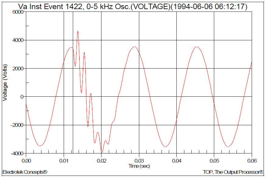
Figure 2 shows a measured 13.8kV distribution feeder current waveform before-and-after energization of a pole-mounted 900 kVAr capacitor bank. Insertion of the bank creates a resonance that results in higher levels (13% THD) of current distortion.
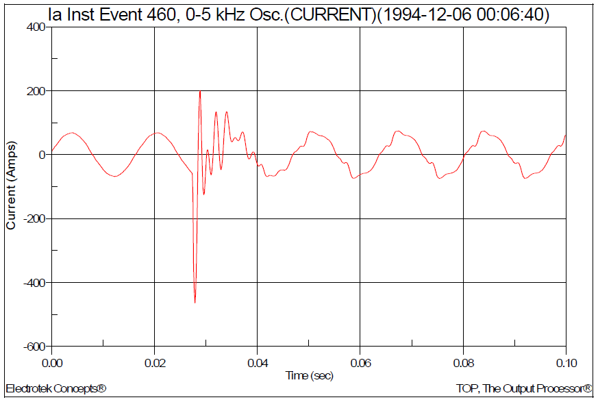
Figure 3 shows a measured 23kV distribution feeder current waveform during back-to-back switching of two 1.8 MVAr capacitor banks. The conductor between the capacitor banks is approximately 4200 feet of 336 MCM aluminum tree wire.

Figure 4 shows a measured distribution substation bus voltage waveform during a multiple restrike event on a 34.5kV capacitor bank switch. The worst-case transient overvoltage was approximately 1.55 per-unit (155%). MOV arresters were installed on the substation transformer.
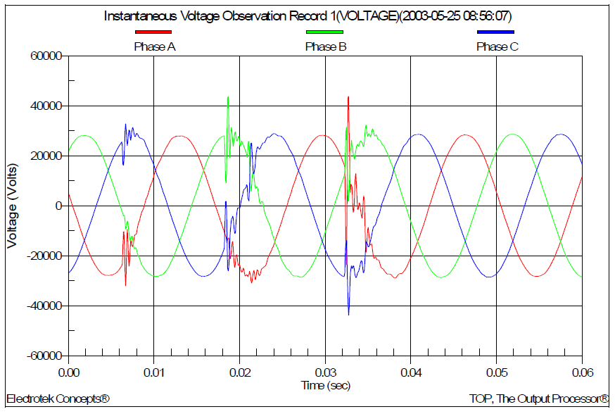
Figure 5 shows a measured voltage waveform during the energization of a 300 kVAr, 15kV distribution feeder capacitor bank. The long pole span (time between phases closing) is because the capacitor bank is switched with three single-phase oil switches.

Figure 6 shows a simulated customer secondary bus voltage waveform (≈3.0 per-unit) during utility distribution substation capacitor bank switching. The customer has power factor capacitors (no arresters) and voltage magnification occurs.
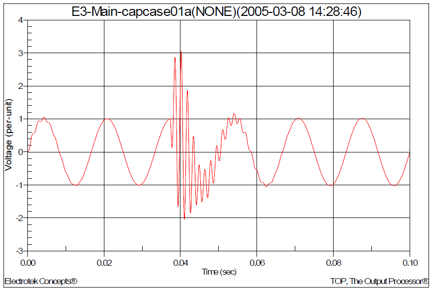
Figure 7 shows a measured distribution bus voltage waveform during a multiple restrike event on a 34.5kV capacitor bank. The bank is protected with MOV arresters and the worst-case transient voltage was approximately 1.98 per-unit (198%).
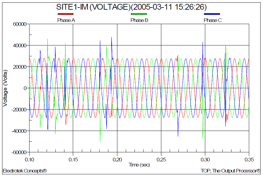
Figure 8 shows a measured distribution substation transformer secondary current waveform during a multiple restrike event (see corresponding voltage waveforms in Error! Reference source not found.) on a 34.5kV capacitor bank. The bank is protected with MOV arresters.

Figure 9 shows a distribution substation transformer secondary current waveform during the energization of two distribution capacitor banks. The peak current on the CT secondary circuit was 401 A.

Figure 10 shows a measured distribution substation transformer secondary current waveform during the energization of a distribution capacitor bank. The harmonic distortion of the steady-state current after the capacitor bank switching is approximately 11%.
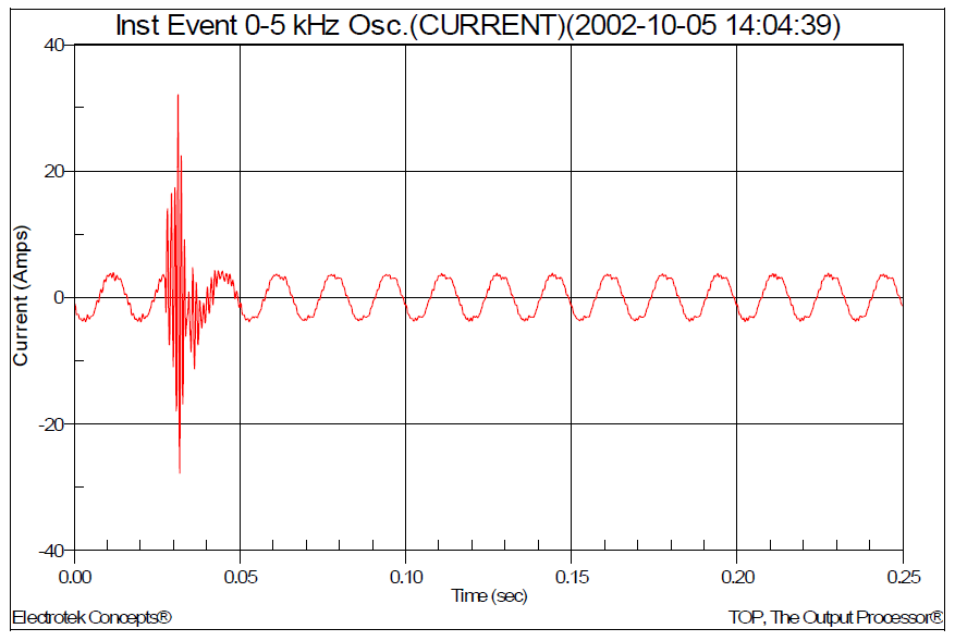
Figure 11 shows a distribution bus voltage waveform during energization of a utility 34.5kV capacitor bank with another bank on the same bus. The resulting transient voltage and voltage rise were 1.5 per-unit (150%) and 1% respectively.
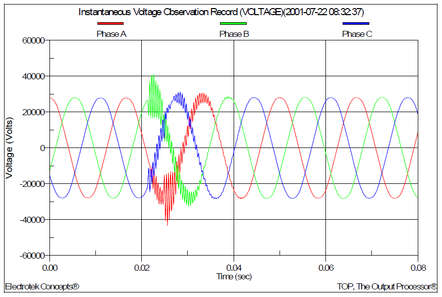
Figure 12 shows a measured distribution feeder current waveform for an arcing capacitor bank switch during energizing of a 300 kVAr pole mounted capacitor bank on a 4.16kV distribution feeder.
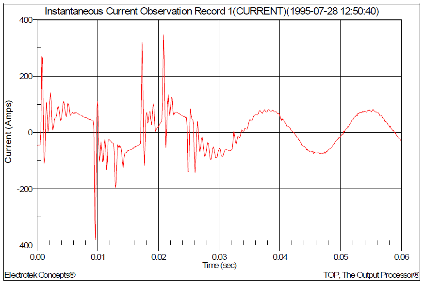
Figure 13 shows a measured distribution feeder current waveform during energization of a distribution capacitor bank. The resulting peak transient current was 561 A and the full load capacitor bank current was approximately 65 amps rms.
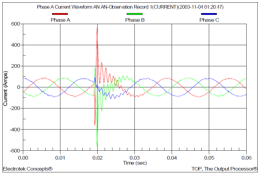
Figure 14 shows a measured distribution feeder voltage during energization of a 4.16kV distribution capacitor bank. The resulting transient voltage was 1.48 per-unit (148%) and the steady-state voltage rise was approximately 0.4%.

SUMMARY
There are many events that can cause a power quality problem. Analysis of these events is often difficult due to the fact that the cause of the event may be related to a switching operation within the facility or to a power system fault hundreds of miles away. This document summarizes several of the more common power quality transient waveforms associated with the application of utility system capacitor banks. The frequent switching of utility capacitor banks coupled with the increasing application of sensitive customer equipment has led to a heightened awareness of several important events, including voltage magnification and nuisance tripping of ASDs.
These concerns have become particularly important as utilities institute higher power factor penalties, thereby encouraging customers to install power factor correction capacitors. In addition, nontraditional customer loads, such as ASDs, are being applied in increasing numbers due to the improved efficiencies and flexibility that can be achieved. This type of load can be very sensitive to the transient voltages produced during capacitor switching.
REFERENCES
G. Hensley, T. Singh, M. Samotyj, M. McGranaghan, and T. Grebe, Impact of Utility Switched Capacitors on Customer Systems Part II – Adjustable Speed Drive Concerns, IEEE Transactions PWRD, pp. 1623-1628, October, 1991.
G. Hensley, T. Singh, M. Samotyj, M. McGranaghan, and R. Zavadil, Impact of Utility Switched Capacitors on Customer Systems – Magnification at Low Voltage Capacitors, IEEE Transactions PWRD, pp. 862-868, April, 1992.
T.E. Grebe, Application of Distribution System Capacitor Banks and Their Impact on Power Quality, 1995 Rural Electric Power Conference, Nashville, Tennessee, April 30-May 2, 1995.
M. McGranaghan, W.E. Reid, S. Law, and D. Gresham, Overvoltage Protection of Shunt Capacitor Banks Using MOV Arresters, IEEE Transactions PAS, Vol. 104, No. 8, pp. 2326-2336, August, 1984.
S. Mikhail and M. McGranaghan, Evaluation of Switching Concerns Associated with 345 kV Shunt Capacitor Applications, IEEE Transactions PAS, Vol. 106, No. 4, pp. 221-230, April, 1986.
T.E. Grebe, Technologies for Transient Voltage Control During Switching of Transmission and Distribution Capacitor Banks, 1995 International Conference on Power Systems Transients, September 3-7, 1995, Lisbon, Portugal.
Electrotek Concepts, Inc., An Assessment of Distribution System Power Quality – Volume 2: Statistical Summary Report, Final Report, EPRI TR-106294-V2, EPRI RP 3098-01, May 1996.
Electrotek Concepts, Inc., Evaluation of Distribution Capacitor Switching Concerns, Final Report, EPRI TR-107332, October 1997.
RELATED STANDARDS
IEEE Standard 18-1992, IEEE Standard 1036-1992
ANSI/IEEE Standard C37.012-1979, ANS/IEEE C37.99-1990
GLOSSARY AND ACRONYMS
ASD: Adjustable-Speed Drive
PWM: Pulse Width Modulation
MOV: Metal Oxide Varistor
TVSS: Transient Voltage Surge Suppressors
