Published by Xinke GAO1,2 , Yapeng LIU3 , Congying WANG4,
School of Electronic, Information and Electrical Engineering, Shanghai Jiao Tong University (1),
Institute of Information Technology Luoyang Normal College (2),
Power Supply of Qingdao Company, Shandong Electric Power Corporation (3),
School of foreign language, Shanghai Jiao Tong University (4)
Abstract. This paper provides the probability-assessment analysis on the characteristic value of the voltage sag by using Monte Carlo stochastic modelling method to stimulate the randomness of the short circuit fault. Furthermore, this article simulates the influence of the protection devices on the voltage sag to ensure the authenticity and the referential reliability. A system with inverse-time protection devices equipped on each lines which could coordinate together are designed to cut off the short-circuit fault. The voltage sag of the designed system is evaluated by the pre-and post system average RMS variation frequency index, and the voltage sag index is compared with the ITIC curves. The simulation results demonstrated that the inverse-curve relay protection equipments are well-coordinated, and the severity and the range of the voltage sag are influenced by the cooperation of the equipped inverse time protection devices.
Streszczenie. W artykule przedstawiono metodę szacowania prawdopodobieństwa wystąpienia zapadu napięcia na podstawie analizy jego charakterystycznych parametrów zamodelowanych metodą Monte Carlo. Ponad to, w celu weryfikacji skuteczności, dokonano symulacji wpływu urządzeń ochronnych na zapady napięcia. Zaprojektowano także system z urządzeniami umożliwiającymi odizolowanie zwarcia w obwodzie od reszty sieci. Wyznaczono współczynnik częstotliwościowy zmienności wartości średniej RMS zapadów napięcia w proponowanym układzie, który następnie porównano z krzywymi ITIC. Przeprowadzone badania symulacyjne potwierdziły skuteczność i szybkość działania systemu. (Wpływ przekaźników ochronnych na współczynnik zapadu napięcia).
Keywords: Voltage sag, Protective relay, Monte Carlo algorithm, simulation.
Słowa kluczowe: zapad napięcia, przekaźnik ochronny, algorytm Monte Carlo, symulacja.
1.Introduction
Owing to the rapid technology proliferation in industrial control processes, as well as the large implementation of sophisticated electrical apparatus, the high power quality is required by manufacturing factories and commercial electrical consumers. The major power quality problems that interested industries are the voltage sag and swell. The existence of voltage sag can cause damaged product, lost production, restarting expenses and danger of breakdown, but voltage swells can cause over heating tripping or even destruction of industrial equipment such as motor drives [1]. Nowadays, most of the equipments used in the industries are mainly based on semiconductor devices and microprocessors and hence these devices are very sensitive to voltage disturbances. Among power disturbances, voltage sags are considered as the most frequent types of disturbances in the field and their impacts on sensitive loads are severe. Voltage sags have attracted many researchers to perform assessment and mitigation related to such power quality disturbances [2].
The current statistical methods to analyse the influence of voltage sag can be divided into stochastic prediction and electromagnetic transient analysis. For the stochastic prediction there are the fault location and the critical distance methods, paper [3] gives a brief comparison: the critical distance method is more suitable for manual project calculation of lower computational accuracy; The fault location method is more precise for programming, and this method can assure a more precise result with enough fault locations. But for both the fault location and the critical distance method, the fault occurrences are manually set, without considering the randomness of the locations and the types of actual faults, the papers [4-9] use the Monte Carlo algorithm and the electromagnetic transient analysis, only taking the definite time delay protection equipment influence into consideration.
At the moment both the mid voltage and low distributive networks apply the three sectional over-current protections, whose shortcomings are that these will generate the unnecessary loss to ensure the selectivity needed to cut down the fault. Nevertheless the inverse-time protection referred in papers [10-18] hold the advantages of self-adaptive functions and less affected by the way of operation. With the development of the digital protection technology, CIGRE and IEEE both establish the standards for the time-inverse relay protection, which are being applied in national low-voltage distributive networks step by step.
To sum up, this paper uses the method which combines the electromagnetic transient simulation and Monte Carlo methods to analyze the low-voltage distributive networks with the inverse-time protection relays installed. This article mainly discusses the influence of the inverse-time protection relays including designing protection relays which effectively coordinate together to cut off the short-circuit fault, and gives an analysis based on the voltage sag criteria such as SARFI (System Average RMS Variation Frequency Index) parameter and ITIC curve. These analysis results could be used for the further studying the impacts of the protective devices for the voltage sag.
2.Setting coordination of inverse-time over-current relays
2.1. Introduction of inverse-time relay
For the moment, there are two criteria for inverse-time relays, which are IEC255-03 [11] and IEEE STD C37.112-1996 [12] with their time-current equations as follows.
Referring to IEC255-03(1989-05) the inverse-time standard formulas are classified into three kinds: inverse, very inverse, and extremely inverse:
INVERSE (FSXTX=1.0):
(1) t = 0.14 x TDS / ((I / Ipu)0.02 -1)
VERY INVERSE (FSXTX=2.0):
(2) t = 13.5 x TDS / ((I / Ipu) -1)
EXTREMELY INVERSE (FSXTX=3.0):
(3) t = 80 x TDS / ((I / Ipu)2 -1)
where I is the current value going into relays, t is time to trigger, TDS is a factor to distinguish each member of a family, Ipu is the pickup current (the smallest value that will trigger the breaker).
Referring to IEEE Std C37.112-1996 the standard formula representing type CO and IAC relays, considering overtravel and resetting characteristics and the relay coordination are as follows:
(4) ttrip(I) = TDS(A / (MP +1) +B) +K
(5) treset(I) = TDS(tp / (1-Mq))
Where ttrip is the operating time to trip in seconds, treset is the operating time to reset in seconds. M is the multiple of pickup current, M = I / Ipu. TDS is time dial operation, and p and q are exponent constant to stand for various characteristics.
2.2. Design of inverse-time relay
The simulation module in this paper is designed as the low-voltage distributive network with the arc-suppression coils. When the power system is under the normal operation, there is no current flowing through the arc-suppression coils. While the network is under the thunder attack or single phase short circuit, the voltage at the neutral point reaches to the value as large as the phase voltage. At the same time, the inductive current which flows through the arc-suppression coils and the capacitive fault current caused by the single phase-to-earth fault are compensated with each other to small amount of residual current. The residual current is not so large enough that cause the arc to extinguish without arousing the overvoltage. The lower fault current makes the longer delay for the inverse-time relay protection operation.
The inverse-time protection relay equipment applies the module built-in PSCAD, and the parameter design is based on extreme inverse-time parameter designed as the following equation by the IEEE Std C37.112-1996 thoroughly explained in paper [12], using very inverse-time standard without considering resetting characteristics here.
(6) ttrip(I) = TDS(3.922 / (M0.02 +1) +0.098) +K
Take example of the simulation analysis of the fault occurred triply. The single phase-to-earth needs the longest time delay for operating the inverse-time relay protection equipments. The theoretical delay time could be got according to the time-current curve in the inverse-time relay module designed in PSCAD.
The PSCAD functions in terms of time sequence, the actual tripping moment ( Tr ) lags behind the theoretical time ( Tt ) at the same current peak ( Ip ). The beginning time and the ending time are put in Tstart and Tend . All these parameters are shown in table 1.
The table 1 and the Fig.1 and Fig.2 prove the excellent cooperations and operations among the inverse-time modules. All the seven lines are equipped with inverse-time relay protection, and the voltage-sag characteristics variations are to be explained later.
Table 1. Protective devices acting time table


3.Simulation analysis considering inverse-time relays
3.1. Introduction of the simulation model
The simulation system structure and the parameter are explained as follows: the voltage grade with 110/25/0.4 kV, Yn / Yn wiring in transformer T1 with a voltage ratio 110/10.5kV; the transformer T2 、T3 、T4 、T5 all configured as Δ – Y0 wiring with a voltage ratio in 25/0.4kV. As shown in Fig.3, the system is of seven lines all with the inverse-time relay protection equipments owning the same characteristic curves, and they are respectively the L1 ~ L3 of 500m length, L4 ~ L7 of 250m length.
Fig. 3. System simulation module
3.2. Probabilities assessment for the simulation results
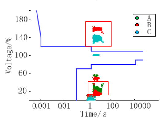
3.2.1 Assessment based on the ITIC curve
The ITIC curve shown in Fig.4 based on large amount of experiment data features the equipment endurance capability standard developed from the CBEMA curve describing the vulnerability level of the information industry equipments to the transient power quality (mainly the voltage sag, rise, short interruption). The curve currently recognized as IEEE446 standard to evaluate the influence of the transient power disturbances explains the capability for the loads to bear the voltage sag.
• Without relay protective devices
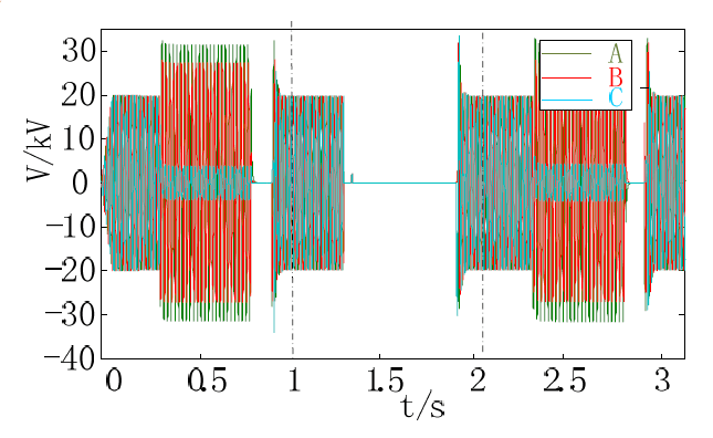
In order to summarize the characteristics of the single phase-to-earth fault, take the A phase as an example shown in the Fig.5 and Fig.6.
As the results shown in Fig.5 and Fig.6, the influence of the transformer Δ – Y that the fault voltage caused by the single phase-to-ground transformed from the TB1 type to the normal type as the N type leads to the significantly lowered dangerous voltage sags at the LV side with excessive voltage conditions disappearing;
According to the historical statistical data, the percentage of the single phase-to-earth is 75%, i.e. the excessive voltage is 75%. Hence the excessive voltage on medium voltage of the B and the C phases caused by the single phase-to-earth fault holds the highest occurrence probability.

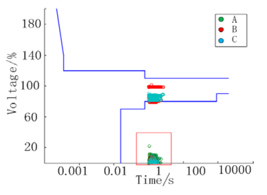
• With relay protective devices
Here presents the simulation results considering the protection configuration between circuit breaker using the time-inverse characteristics and reclosers (with 100ms reclosing interval) with different mean fault time duration at 100ms, 600ms and 1s.
From Fig.7 and Fig.8, the trips whose numbers are almost the same with one of the interruptions do not intensively increase because most trips are on the faulted feeder generated from interruptions caused by three-phase faults.
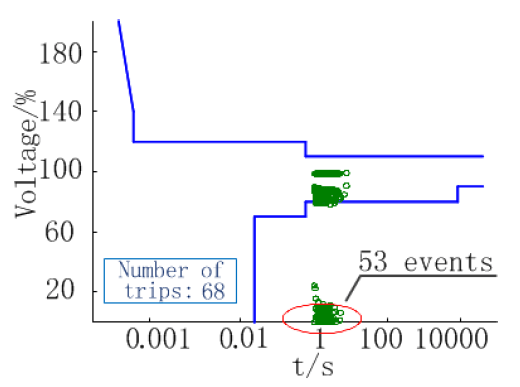
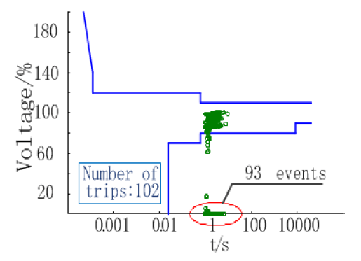
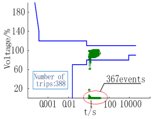
According to Fig.8, compared with Fig.9, the protective devices work more precisely as the fault duration gets enough longer because the value of the short circuit current is lower with the arc-suppression coils equipped. With shorter mean fault duration time, most interruptions caused by three-phase faults rather than single-phase ones will cause an equipment trip only to loads located on the faulted feeder while with longer mean time duration most trips will be caused by single-phase faults.
3.2.2 Calculation based on the SARFI index
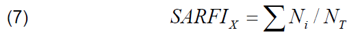
The characteristic measures for the voltage sag are the RMS offset and the voltage sag duration time, hence the most common index is the SARFI (System Average RMS Variation Frequency Index). One of the two common forms is the statistic index number—SARFIx used to explain a specific threshold voltage x which is meant to get the probability of the voltage RMS below the voltage threshold x. For a certain node the SARFIx could be calculated by the following expression:
The SARFIx of the whole system could be obtained by the following expression:
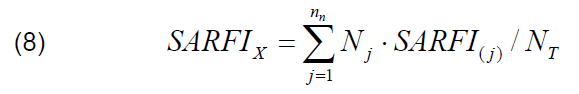
Where Ni is the number of customers whose voltage RMS under threshold voltage; NT is the number of the entire assessed customer; nn is the number of nodes in the whole system; Nj is the number of the customers belonging to the node; and SARFI(j) is the SARFI value of the specific node.
Calculate all the values of SARFI1.1_MV, SARFI0.9_MV, SARFI0.8_LV, SARFI0.6_LV (SARFI1.1_MV means the RMS is over 110%). The results of SARFI refer to table 2. The longer duration time makes the SARFI1.1_MV value lower because it generates more chances for the protective devices to trip when the single-phase-to-ground fault happens in the system with the arc-suppression coils equipped. For the LV-level side, the lowest SARFI values with a threshold voltage below 90% are achieved when protective devices reject to operate, because most of the voltage sags generated by single-phase-to-ground faults are higher than the nominal voltage by 60%.
Table 2. SARFI calculation results

4.Conclusion
The comparison and contrast between the ITIC curve and the voltage sag index before and after the protective devices equipped show that the longer the fault duration lasts, the higher probability for the protective devices to operate, the more times for the loads on the low voltage to trip, i.e. the longer time for the sensitive loads to shut down. Therefore, the extent of the voltage sag become more severe, the main reason of which is the longer time demand for the protective devices to operate when single phase-to-ground fault happens in the arc-suppression coils grounding mode.
Here only presents the configuration of reclosers and circuits breakers. Further studies are expected to be analysed with other protective devices (e.g. fuses and sectionalizers) added and other reclosing cooperating patterns.
5. Acknowledgements
This work was supported by the Shanghai Jiao Tong University Innovation Fund for Postgraduates under Grant No.AE030202, Henan Tackle Key Problem of Science and Technology under Grant No.102102210454, the Foundation of Education Committee of Henan Province under Grant No.2011B520028, the Cultivated Funded Project of Luoyang Normal College under Grant No.10000859.
REFERENCES
[1] Dehini R., Bassou A.,Chellali B., Generation of voltage references using Multilayer Feed Forward Neural Network, Przeglad Elektrotechniczny, 88(2012), No. 4A, 289-292.
[2] Ibrahim A. A., Mohamed A., Shareef H., et al., A new approach for optimal power quality monitor placement in power system considering system topology, Przeglad Elektrotechniczny, 88(2012), No. 9A, 272-276.
[3] Won D.J., Ahn S.J.,Moon S.I., A modified sag characterization using voltage tolerance curve for power quality diagnosis, IEEE Trans. On Power Delivery, 20(2005), No. 4, 2638-2643.
[4] Martinez J.A.,Martin-Arnedo J., Voltage sag stochastic prediction using an electromagnetic transients program, IEEE Trans. On Power Delivery, 19(2004), No. 4, 1975-1982.
[5] Yunting S., Yongji G.,Ruihua Z., Probabilistic Assessment of Voltage Sags and Momentary Interruption Based on MONTECARLO Simulation, Automation of Electric Power Systems, 27(2003), No. 18, 47-51.
[6] Martinez J.A.,Martin-Arnedo J., Voltage sag analysis using an electromagnetic transients program, in Power Engineering Society Winter Meeting,(2002). 1135-1140.
[7] Martinez J.A.,Martin-Arnedo J., Voltage sag studies in distribution Networks-part I: system modeling, IEEE Trans. On Power Delivery, 21(2006), No. 3, 1670-1678.
[8] Martinez J.A.,Martin-Arnedo J., Voltage sag studies in distribution networks-part II: voltage sag assessment, IEEE Trans. On Power Delivery, 21(2006), No. 3, 1679-1688.
[9] Martinez J.A.,Martin-Arnedo J., Voltage sag studies in distribution Networks-part III: Voltage sag index calculation, IEEE Trans. On Power Delivery, 21(2006), No. 3, 1689-1697.
[10] Benmouyal G., Meisinger M., Burnworth J., et al., IEEE standard inverse-time characteristic equations for overcurrent relays, IEEE Trans. On Power Delivery, 14(1999), No. 3, 868-872.
[11] Tan JC, McLaren PG, Jayasinghe RP, et al., Software model for inverse time overcurrent relays incorporating IEC and IEEE standard curves,(2002). 37-41 vol. 1.
[12] Standard B., Electromagnetic compatibility (EMC) Testing and measurement techniques, voltage dips, short Interruptions and voltage variations immunity tests, BS END, 61(000-4.
[13] Urdaneta A.J., Restrepo H., Marquez S., et al., Coordination Of directional overcurrent relay timing using linear programming, IEEE Trans. On Power Delivery, 11(1996), No. 1, 122-129.
[14] Wang J., Chen S.,Lie TT, System voltage sag performance estimation, IEEE Trans. On Power Delivery, 20(2005), No. 2, 1738-1747.
[15] Taylor C.W., Concepts of undervoltage load shedding for voltage stability, IEEE Trans. On Power Delivery, 7(1992), No.2, 480-488.
[16] Gupta CP,Milanovic J.V., Probabilistic assessment of equipment trips due to voltage sags, IEEE Trans. On Power Delivery, 21(2006), No. 2, 711-718.
[17] Aung M.T.,Milanovic J.V., Stochastic prediction of voltage sags by considering the probability of the failure of the protection system, IEEE Trans. On Power Delivery, 21(2006), No. 1, 322-329.
[18] Han W., Chenzhao YU,Jianwen ZHANG X.C.A.I., Control of Voltage Source Inverter with an LCL Filter without Voltage Sensors, Przeglad Elektrotechniczny, 88(2012), No. 5b, 119-122.
Authors: Xinke GAO, Ph.D.Candidate of Department of Instrument Science and Engineering, School of Electronic, Information and Electrical Engineering, Shanghai Jiao Tong University, No. 800 of Dongchuan Road, Minhang District, Shanghai, CHINA. He is also an associate Professor of Institute of Information Technology, Luoyang Normal College,CHINA. gxk622@163.com
Source & Publisher Item Identifier: PRZEGLĄD ELEKTROTECHNICZNY, ISSN 0033-2097, R. 89 NR 5/2013
