Published by Electrotek Concepts, Inc., PQSoft Case Study: Distribution Feeder Wind Turbine Generator Analysis, Document ID: PQS1206, Date: January 26, 2012.
Abstract: This case study presents a distribution feeder wind turbine generator analysis. The investigation included several potential causes of turbine and feeder overcurrents and overvoltages, including wind speed variations, cut-out and cut-in switching operations, ground faults, and islanding during feeder isolation. Mitigation alternatives for high temporary overvoltages (TOV) on distribution feeders include application restrictions, grounding transformers, direct transfer trip schemes, and crowbar switches.
INTRODUCTION
A distribution feeder wind turbine generator analysis case study was completed for the system shown in Figure 1. The case study investigated several potential causes of turbine and feeder overcurrents and overvoltages, including wind speed variations, cut-out and cut-in switching operations, ground faults, and islanding during feeder isolation. The simulations were completed using the PSCAD® transient program. A transient model was created to simulate a relatively weak distribution feeder with a single wind turbine generator connected near the end of the feeder. The resulting voltages and currents during various switching and fault events were determined.

SIMULATION ANALYSIS
The simulation model included a 12.47kV substation and distribution feeder supplying a 1.5 MW wind turbine generator connected near the end of the feeder. The model included a 600 kVAr capacitor bank connected at the substation bus and several additional 600 kVAr capacitor banks on the feeder. There was one distribution feeder included in the model.
The model was designed so turbine and feeder overcurrents and overvoltages during wind speed variations, turbine cut-out and cut-in switching operations, ground faults, and islanding during feeder isolation could be determined. The accuracy of the simulation model at 60 Hz was determined using simulated fault current magnitudes and other steady-state quantities, such as cable line charging (MVAr) and feeder load flow values (MW & MVAr). The representation of the system short-circuit equivalent at the 12.47kV source substation included:
Three-phase (I3φ) fault current: 4,000 A @ -85.0° (86 MVA)
Single-line-to-ground (IφG) fault current: 3,000 A @ -85.0° (65 MVA)
These values were converted to ohms for the PSCAD representation, which included a three-phase voltage source with positive and zero sequence impedances and a 150 Ω damping resistor.
The 12.47kV distribution feeder and underground cable sections were modeled using the following impedance data:
Conductor: 4/0 AWG AL
Length: 5,550 feet
Positive sequence impedance (Z1): 0.1087 +j0.0653 Ω/1000’
Zero sequence impedance (Z0): 0.2567 +j0.0688 Ω/1000’
Line charging (B/2): 8.7 μmhos/1000’
It was assumed that positive and zero sequence line charging values were the same. The coupled π-section model was used to model each cable section. That assured accurate representation of both the series impedances, as well as the line charging of the underground feeder cable sections.
The turbine transformer was modeled using the three-phase, two-winding transformer model. The turbine step-up transformer data included:
Three Phase Rating: 2,000 kVA
Secondary Voltage: 480 V (grounded-wye)
Primary Voltage: 12.47 kV (grounded-wye)
Nameplate Impedance: 5.75% (X/R Ratio = 10)
The 1.5 MW (1.67 MVA @ assumed 0.90 PF) wind turbine generator was modeled using a wound rotor induction machine model. The wound rotor induction machine can be used to represent an induction generator and it can be operated in either ‘speed control’ or ‘torque control’ modes. One 150 kVAr capacitor bank was connected to the 480 V secondary for reactive power support.
The wind turbine generator was controlled using PSCAD’s built-in wind turbine component. The inputs to the component include wind speed (Vw – m/s) and the mechanical speed of the machine connected to the turbine (W – rad/s). The pitch angle (Beta) of the turbine blades is entered in degrees if pitch control is enabled. If pitch control is disabled, the turbine is switched to stall control mode, where the turbine’s aerodynamic characteristics will determine the output torque. The component outputs include torque (Tm) and power (P), which are in per-unit based on the machine’s MVA rating.
The wind speed component models the wind speed available to the wind turbine generator. The input of the component is an external signal representing wind speed (ES – m/s) and the output is the wind speed available to the turbine (Vw – m/s). This component can be used to study a wind gust (or ramp) to determine the response of the control system. The wind turbine characteristics determine the input torque variations (torque control mode) supplied to the induction generator.
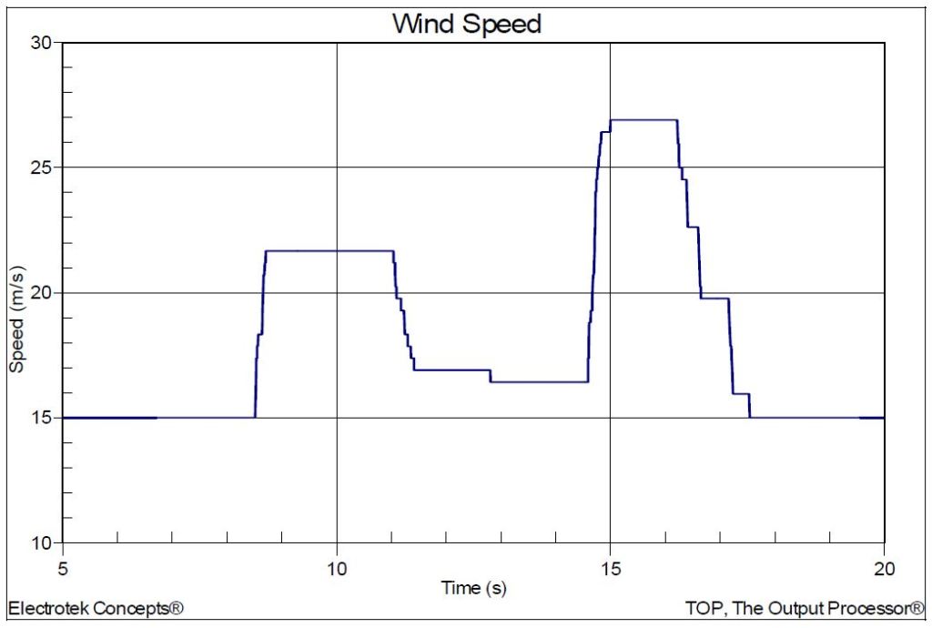
Case 1 included simulating a wind speed variation. The simulation time was 20 seconds and the timestep was 50μsec. The average wind speed was 15 m/s. The simulated wind speed is shown in Error! Reference source not found.. The figure shows the simulated wind speed between 5 and 20 seconds. The maximum speed gust was 27 m/s.
Figure 3 shows the corresponding turbine current (Phase A) for Case 1. The maximum value was 17.0 kA during the initial abrupt wind speed change between 8 and 9 seconds.
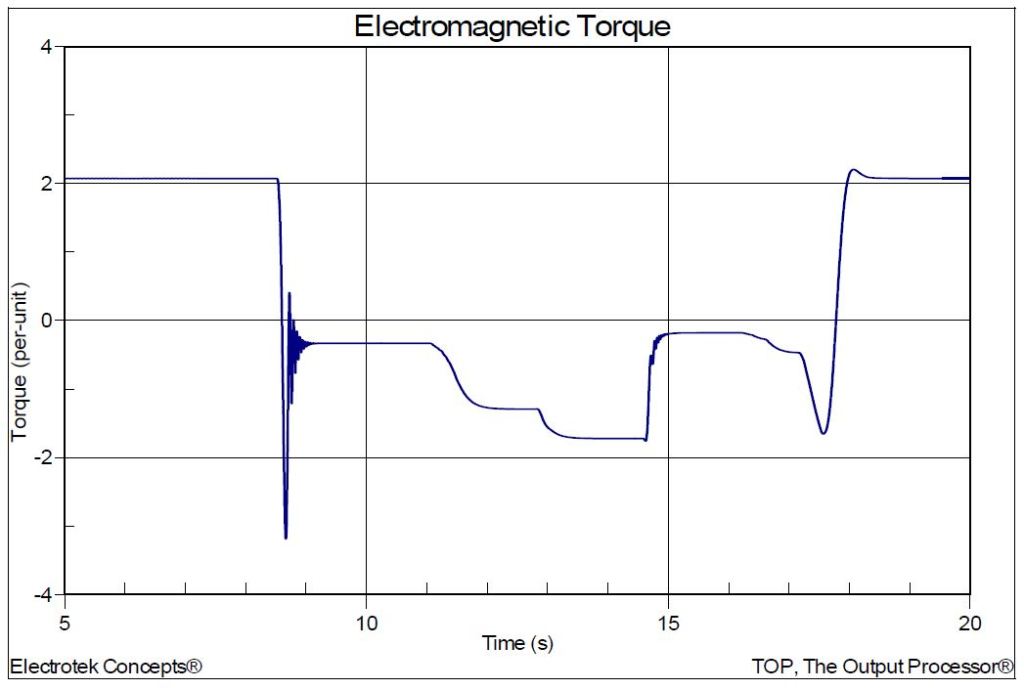
Figure 4 shows the simulated electromagnetic torque for Case 1, while Figure 5 shows the corresponding turbine power.


Case 2 included simulating cut-out and cut-in switching operations. The simulation time was 20 seconds and the average wind speed was 15 m/s. The sequence of events for the switching operation included opening (cut-out) the low voltage circuit breaker supplying the wind turbine generator at 10 seconds and closing (cut-in) the circuit breaker back in at 15 seconds.
Figure 6 shows the turbine current (Phase A) for Case 2. The peak current value was 78.2 kA when the circuit breaker opens. The oscillatory transient voltage is due to the interaction with the power factor correction capacitor.
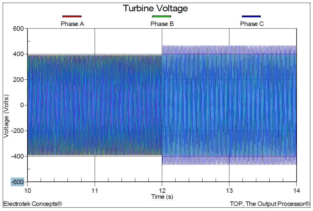
Figure 7 shows the corresponding turbine voltage (Phase A) for Case 2. The peak voltage was 471 V (1.20 per-unit) when the circuit breaker opens.
Case 3 included simulating a ground fault at the low voltage wind turbine generator secondary bus. The simulation time was 20 seconds and the average wind speed was 15 m/s. The sequence of events for the ground fault included applying a single-phase-to-ground fault (Phase A) on the turbine generator bus. The fault did not clear during the simulation.
Figure 8 shows the turbine current (Phase A) for Case 3. The peak current value was 30.9 kA when the fault occurs.
Figure 9 shows the turbine voltage for Case 3. The fundamental frequency temporary overvoltage was 464 V (1.19 per-unit) during the single-phase fault. Figure 10 shows the corresponding 12.47kV feeder voltage. The temporary overvoltage was 12.014kV (1.18 per unit).


Case 4 involved simulating an islanding condition by opening the circuit breaker on the 12.47kV primary side of the turbine transformer. The simulation time was 20 seconds and the average wind speed was 15m/s. The sequence of events for the islanding case included opening the circuit breaker at 10 seconds. There were no faults applied during the simulation.
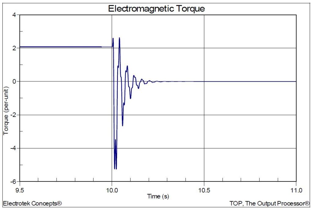
Figure 11 shows the turbine current (Phase A) for Case 4. The peak current value was 32.5 kA when the circuit breaker opens. Figure 12 shows the corresponding simulated electromagnetic torque for Case 4.

SUMMARY
This case study presents a distribution feeder wind turbine generator analysis. The investigation included several potential causes of turbine and feeder overcurrents and overvoltages, including wind speed variations, cut-out and cut-in switching operations, ground faults, and islanding during feeder isolation.
Voltage regulation, islanding, and reverse power flow, and the resulting potentially severe temporary overvoltages, are three of the most important operating considerations for distributed generation applications having a single large wind turbine generator on a relatively weak distribution feeder. These conditions are typically not dependent on the wind turbine generator type and therefore may occur for any of the turbines.
Mitigation alternatives for high temporary overvoltages on distribution feeders include application restrictions, grounding transformers, direct transfer trip schemes, and crowbar switches.
REFERENCES
- IEEE Recommended Practice for Measurement and Limits of Voltage Fluctuations and
Associated Light Flicker on AC Power Systems, IEEE Std. 1453-2004, IEEE, 2005, ISBN: 0-
7381-4482-7. - IEEE Recommended Practice for Grounding of Industrial and Commercial Power Systems, IEEE
Std. 142 (IEEE Green Book), IEEE, November 2007, ISBN: 0738156392. - IEEE Recommended Practice for Monitoring Electric Power Quality,” IEEE Std. 1159-1995, IEEE,
October 1995, ISBN: 1-55937-549-3. - IEEE Recommended Practices and Requirements for Harmonic Control in Electrical Power
Systems, IEEE Std. 519-1992, IEEE, ISBN: 1-5593-7239-
RELATED STANDARDS
IEEE Std. 142
IEEE Std. 1453
GLOSSARY AND ACRONYMS
DFT: Discreet Fourier Transform
PCC: Point of Common Coupling
TDD: Total Demand Distortion
TOV: Temporary Overvoltage
