Published by Stanisław CZAPP , Gdańsk University of Technology, Faculty of Electrical and Control Engineering
Abstract. In the paper spectral analysis of the distorted earth fault currents in circuits with variable speed drives is performed. Effectiveness of protection against electric shock using residual current devices in circuits with variable speed drives for various PWM frequencies is evaluated. Operational characteristic of the proposed residual current device is presented.
Streszczenie. W artykule przedstawiono analizę widmową odkształconego prądu ziemnozwarciowego z obwodu silnika o regulowanej prędkości obrotowej za pomocą przemiennika częstotliwości. Oceniono skuteczność ochrony przeciwporażeniowej wykorzystującej wyłączniki różnicowoprądowe przy różnych wartościach częstotliwości PWM przemiennika. Przedstawiono charakterystykę działania proponowanego wyłącznika różnicowoprądowego. (Wpływ częstotliwości PWM na skuteczność ochrony przeciwporażeniowej wykorzystującej wyłączniki różnicowoprądowe).
Keywords: variable speed drives, protection against electric shock, residual current devices.
Słowa kluczowe: napędy o regulowanej prędkości obrotowej, ochrona przeciwporażeniowa, wyłączniki różnicowoprądowe.
Introduction
Electrical devices should not introduce risk of electric shock either in normal service or in the case of a single fault condition. In each part of an installation one or more protective measures shall be applied [1]:
– automatic disconnection of supply (with overcurrent and/or residual current devices),
– double or reinforced insulation,
– electrical separation for the supply of one item of the current-using equipment,
– extra-low-voltage (SELV or PELV).
The most commonly used of the above mentioned protective measures is the automatic disconnection of supply. Specific and difficult for analysis of the effectiveness of protection against electric shock in the case of direct or indirect contact are circuits with variable speed drives. Earth fault in the output terminals of inverter or in motor terminals (Fig. 1) results in significant current in the PE conductor. Overcurrent or residual current devices should operate. Direct contact (Fig. 1) in the line between inverter and motor gives a low value of current but it is very dangerous for persons because the whole fault current flows through the human body. Only high sensitivity residual current devices may operate effectively. The earth fault current in circuits with variable speed drives is distorted and it has the fundamental significance for proper operation of protective devices, especially the residual current devices. For sinusoidal waveform, operational characteristics of residual current devices depend on earth fault current frequency, for a distorted waveform the most important is the order of harmonics [2–9]. Earth fault current in the output terminals of inverter comprises harmonics whose order depends on the PWM (Pulse Width Modulation) frequency. For the specified motor speed range, the PWM frequency component dominates in the earth fault current. The next paragraphs present analysis of the earth fault current distortion and impact of the PWM frequency on the residual current devices tripping current.
Earth fault current analysis
Spectral analysis of the earth fault current in circuits with variable speed drives was performed. Model of a circuit with variable speed drives was generated using TCad software [10, 11]. In the model voltage source inverter with PWM modulation and U/f = const is used. Computer simulation was verified under laboratory conditions. Both the computer simulation and the laboratory test gave similar results.
Fig. 2 presents computer simulation of the earth fault currents in a circuit with variable speed drives. This computer simulation was performed for 50 Hz motor supply voltage frequency (in this paper named “motor frequency”) and for the following PWM frequencies: 1 kHz, 3 kHz. The currents comprise harmonics, especially high-order harmonics. The spectrum of these currents is presented in Fig. 3.

RCD – residual current device, FC – frequency converter, M – motor, IE – earth fault current, IT – touch current
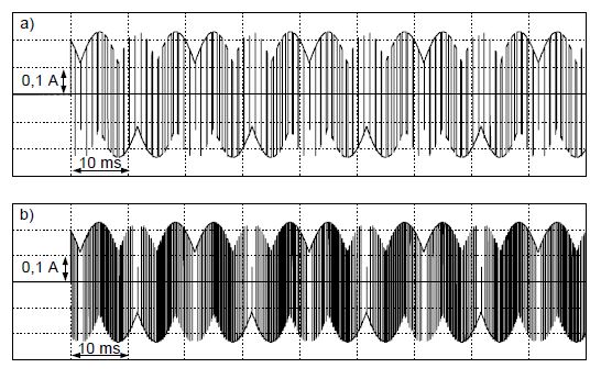
(TCad simulation). Motor frequency 50 Hz, PWM frequency: a) 1 kHz, b) 3 kHz


The order of harmonics corresponds with the applied PWM frequency. Apart from the PWM frequency component, current components appear which are a multiple of the PWM frequency. The lower the motor frequency, the higher the participation of PWM frequency component.
Fig. 4 presents, as an example, the earth fault current for very low motor frequency, equal to 1 Hz. This is the result of TCad simulation (Fig. 4a, Fig. 4b) and laboratory test (Fig. 4c). For a very low motor frequency, the PWM component significantly exceeds other components of the earth fault current – the dominating component is PWM component. In this waveform the PWM component becomes fundamental. Wide spectral analysis performed during laboratory test (Fig. 4c) indicates that the earth fault current also contains high level harmonics which are the multiple of PWM frequency.
PWM frequency versus tripping current
The effect of PWM frequency on the operational characteristics of residual current devices and effectiveness of protection against electric shock was tested under laboratory conditions. Numerous groups of residual current devices (over forty devices) were tested. The residual current devices under test were marked RCD1, RCD2, etc.
Taking into account spectral analysis of earth fault current, distorted currents were generated using programmable power supply [12]. It allows to avoid the impact of noises on the tripping current, which occur in real circuits with variable speed drives. The programmable power supply enables to generate waveforms comprising fundamental and one or several harmonics. The percentage of harmonic-to-fundamental value of individual harmonic and phase angle of individual harmonic may be specified precisely. It is possible to obtain current waveforms similar to earth fault currents in real circuit with variable speed drives. There were three types of test currents reflecting the earth fault current in circuit with variable speed drives. The first type of the current comprised harmonics which dominate in the earth fault current in the case of fault in the motor terminals for motor frequency equal to 50 Hz. Similarly, the second type of current for motor frequency equal to 25 Hz and the third type of current for motor frequency equal to 1 Hz.
As it was presented in [7], the tripping current for the same PWM frequency, reaches the highest value for the lowest motor speed. For this reason an extended test, for various PWM frequencies, was performed for motor frequency equal to 1 Hz (very low motor speed).
Fig. 5 and Fig. 6 present results of the extended test –tripping current of residual current devices: IΔn = 30 mA and IΔn = 300 mA, respectively. The tripping current was checked for motor frequency equal to 1 Hz and the following PWM frequencies: 500 Hz, 1000 Hz, 1500 Hz, 2000 Hz and 2500 Hz. Comparison of the tripping currents of various residual current devices allows to affirm that the higher the PWM frequency the higher the tripping threshold.
Apparently similar residual current devices in terms of the technical data may have significantly different operational characteristics. It is clearly visible comparing RCD6 to RCD10 (Fig. 5a) and RCD27 to RCD30 (Fig. 6a). RCD6 trips out for all the test currents but RCD10 does not trip out at all for the PWM frequency equal to or higher than 1000 Hz. Regardless of the PWM frequency, for very low motor speed the tripping current of the tested residual current devices either significantly exceeds the rated residual current IΔn or the residual current devices do not trip at all. Residual current device which has the tripping current many times higher than IΔn or does not trip at all can not ensure effectiveness of protection against electric shock.
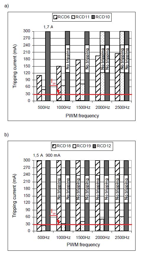
Negative effect of the earth fault current with high frequency components can be eliminated by using a solution proposed by the author. Structure of the new residual current device of IΔn = 300 mA was described in [13]. It allows to achieve steady tripping current for strong distorted earth fault current. Properties of this residual current device for strong distorted earth fault current are presented in Fig. 6c and compared with other residual current devices (Fig. 6a, Fig. 6b) of IΔn = 300 mA. The operational characteristics presented in Fig. 6a, Fig. 6b are typical of most residual current devices used in practice. Their tripping threshold rises with rising PWM frequency. The operational characteristic of the proposed residual current device presented in Fig. 6c indicates that tripping current does not exceed the rated operating residual current IΔn regardless of the PWM frequency. The tripping current is within 0,5IΔn ÷ 1,0IΔn as for the sinusoidal (50/60 Hz) earth fault current and is in accordance with the standard [14].
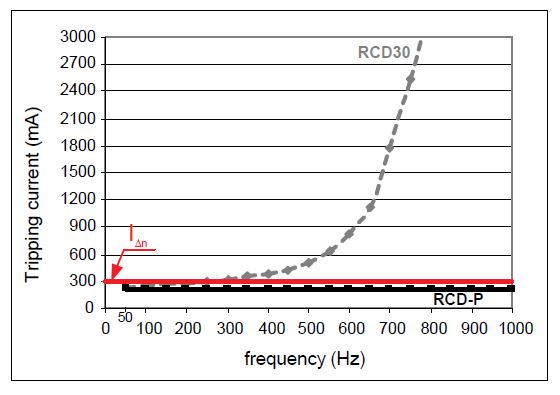
Such favourable operational characteristic for strong distorted earth fault current is a result of favourable operational characteristic for sinusoidal waveform within a wide frequency range. Fig. 7 presents comparison of the operational characteristics within the 50 Hz to 1000 Hz frequency range for the proposed RCD-P residual current device and the residual current device numbered RCD30 (as in Fig. 6a).

The proposed residual current device, contrary to the RCD30, has steady tripping current in the whole range. The new RCD-P residual current device is voltage independent, no auxiliary power is necessary for its operation. All power is derived from the earth (residual) current. It is an important advantage of this solution.
Conclusions
The effectiveness of protection against electric shock in circuits with variable speed drives is difficult to evaluate in the case of direct or indirect contact. Disconnection of supply by residual current devices depends on the applied PWM frequency, present motor speed and real operational characteristics of the residual current device. For proper operation of residual current devices it is better to apply a relatively low PWM frequency. However, now there is a tendency to use high PWM frequency, so commonly used residual current devices are expected to have very high tripping current and in some cases may not trip at all. Special residual current devices, as proposed by the author, designed for strong distorted earth fault current with high-order harmonics should be used.
REFERENCES
[1] IEC 60364-4-41 Low-voltage electrical installations (multipart standard)
[2] Grünebast G., Allstromsensitive Fehlerstromschutzeinrichtungen. Teil 2: Vorschriftsmässiger Einsatz, Elektropraktiker, 62, (2008), no. 2, 144-149
[3] Lee T. M., Chan T. W., The effects of harmonics on the operational characteristics of residual current circuit breakers, Int. Conf. on Energy Management and Power Delivery, Proceedings of EMPD ’95. 21-13 Nov., 1995, Vol. 2, 715-719
[4] Schoneck J., Nebon Y., LV protection devices and variable speed drives, Cahier technique no. 204, Schneider Electric 2002
[5] Siedelhofer B., Muschong M., Fehlerstrom-Schutzeinrichtungen bei besonderen Anwendungen (2). Auswahl und Einsatz, Der Elektro- und Gebäudetechniker, (2005), no. 8, 46-48
[6] Czapp S., The effect of earth fault current harmonics on tripping of residual current devices, Przegląd Elektrotechniczny, (2009), no. 1, 196-201
[7] Czapp S., The impact of higher-order harmonics on tripping of residual current devices, Proceedings of the 13th Int. Power Electronics and Motion Control Conf. EPE-PEMC2008, Poznań, Poland, 1-3 September 2008, 2082-2088
[8] Czapp S., Działanie wyłączników różnicowoprądowych przy podwyższonej częstotliwości prądu różnicowego, Elektro.info, 68, (2008), no. 10, 80-83
[9] Czapp S., The effect of PWM frequency on the effectiveness of protection against electric shock using residual current devices, Proceedings of the 10th Conference-Seminar International School on Nonsinusoidal Currents and Compensation ISNCC2010, Łagów, Poland, 15-18 June 2010, 32-36
[10] TCad 7 – Pakiet symulacyjny do analizy układów energoelektronicznych i układów napędu przekształtnikowego, Copyright © Wydział Elektrotechniki i Automatyki Politechniki Gdańskiej
[11] Bełdyc k i Ł., Analiza skuteczności ochrony przeciwporażeniowej w obwodach z pośrednimi przemiennikami częstotliwości, Praca dyplomowa magisterska, Politechnika Gdańska, (2008)
[12] KIKUSUI: Multifunctional AC Power Supply PCR-LA Series and Quick Wave Sequencer SD04-PCR-L
[13] Czapp S., Elimination of the negative effect of earth fault current higher frequency on tripping of residual current devices, Elektronika ir Elektrotechnika, 91, (2009), no. 3, 85-88
[14] IEC/TR 60755:2008 General requirements for residual current operated protective devices. 2nd edition
Author: dr hab. inż. Stanisław Czapp, Gdańsk University of Technology, Faculty of Electrical and Control Engineering, ul. Narutowicza 11/12, 80-233 Gdańsk, E-mail: s.czapp@ely.pg.gda.p
Source & Publisher Item Identifier: PRZEGLĄD ELEKTROTECHNICZNY (Electrical Review), ISSN 0033-2097, R. 87 NR 1/2011
