Published by Electrotek Concepts, Inc., PQSoft Case Study: Customer Adjustable-Speed Drive Motor Failure Evaluation, Document ID: PQS1010, Date: October 15, 2010.
Abstract: This case study presents a customer adjustable-speed drive motor winding failure analysis. The study investigated the potential for severe high frequency transient overvoltages at induction motor terminals for an adjustable-speed drive that utilized a pulse-width modulation inverter, along with a significant length of cable between the inverter and motor. Several power conditioning mitigation alternatives including series reactors and motor terminal filters were evaluated using computer simulations.
INTRODUCTION
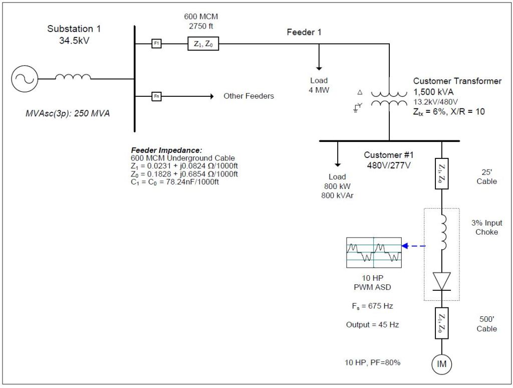
A customer adjustable-speed drive (ASD) motor winding failure case study was completed for the system shown in Figure 1. The case study investigated the potential for severe high frequency transient overvoltages at induction motor terminals for an adjustable-speed drive that utilizes a pulse-width modulation (PWM) inverter, along with a significant length of cable between the inverter and induction motor. Several power conditioning mitigation alternatives, such as series reactors/chokes and motor terminal filters, were evaluated using computer simulations.
The simulations for the case study were completed using the PSCAD program. The accuracy of the simulation model was verified using three-phase and single-line-to-ground fault currents and other steady-state quantities. The circuit consisted of a 34.5 kV utility substation supplying a 1,500 kVA customer step-down transformer, along with a 10 hp PWM adjustable-speed drive with a 500 foot cable segment between the inverter and motor terminals. A high frequency, distributed parameter transmission line model was required to accurately represent the traveling wave (reflections) effects of the motor cable. There was also a standard 3% input choke on the drive, which resulted in a current distortion value of approximately 40.9%. A detailed drawing of the adjustable-speed drive and induction motor configuration is shown in Figure 2.
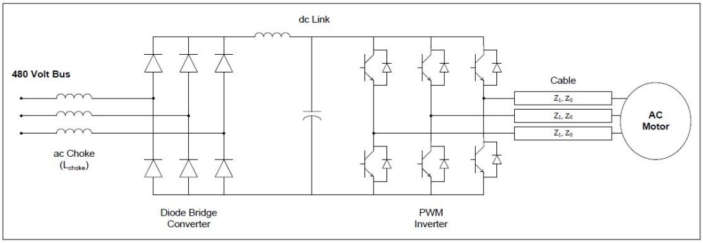
Adjustable-speed drives for most small and medium induction motors utilize voltage source inverters to provide variable frequency ac output. The common drive structure adopted by the industry consists of an uncontrolled diode-bridge rectifier, dc link, and pulse-width modulation voltage source inverter as illustrated in Figure 3. The dc link for this type drive includes a ripple smoothing capacitor. The inverter output waveform is generated by a series of step-like functions. An ideal step-change in the output voltage is prevented by stray parameters of the circuit and commutation of switching devices from one phase to another. Steep-front waveform generation is one of the inherent characteristics of a high switching frequency voltage source inverter.
SIMULATION RESULTS
The output voltage of the pulse-width modulation inverter is a potential problem for the induction motor. Both the frequency and magnitude of the output voltage are adjusted by controlling the inverter’s operation. State-of-the-art voltage source inverters are based on insulated gate bipolar transistor technology. With these devices, the inverter operates with a switching frequency ranging from tens of Hz to tens-of-thousands of Hz. Figure 4 shows an example output voltage of a pulse-width modulation drive (measurement location #1 on Figure 3). The switching frequency of the most commonly used pulse-width modulation drives is in the range of 1,000 Hz to 5,000 Hz. The rise times of the pulses can be approximately 10μs to 0.1μs.
The problem occurs on the output of the inverter at the drive terminals. The high switching frequency of the inverter allows sophisticated control schemes to be implemented. One of the advantages of the high switching frequency inverter is the reduction of low order harmonics, which results in a reduction of output filter duty. However, this benefit can only be achieved under certain circuit conditions. Under some conditions, the fast changing voltage resulting from high frequency switching operation of inverter can create severe insulation problems for induction motors.
Machine insulation integrity is influenced by the rate-of-change of voltage as well as the transient overvoltage magnitude. A voltage with a high rate-of-change tends to be distributed along a motor’s windings unevenly. This uneven distribution causes a significant over-stress across ending turns resulting in turn-to-turn insulation failure. In practice, it is common for the drive and the motor to be separated by relatively long lengths of cable. In addition, the characteristic impedance of the induction motor can be ten to one hundred times that of the characteristic impedance of the cable connecting the drive to the induction motor.
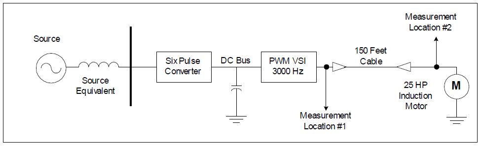
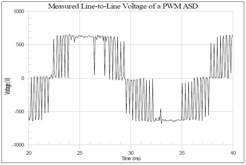
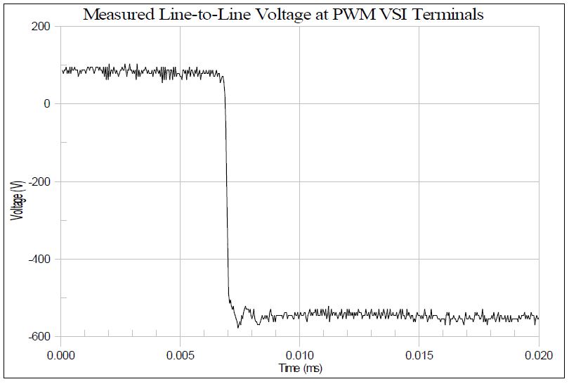
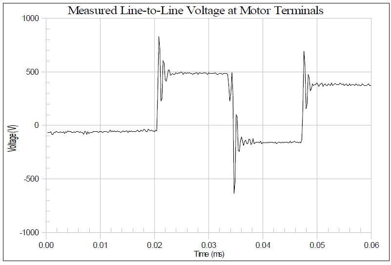
Figure 5 shows a transition in one of the pulses at the inverter (measurement location #1). Notice that when the voltage changes from zero to its full negative value, there is no significant over-shoot or overvoltage. At the motor terminals, however, the transition of one of the pulses at the motor terminals shows an overvoltage of approximately 1.7 per-unit, as shown in Figure 6 (measurement location #2). The overvoltage and the resulting ringing occur at both the front and rear of each pulse. Depending on the operation pattern of the adjustable-speed drive, similar transients may occur 20 to 100 times per 60 Hz cycle.
The most harmful effect of the inverter output occurs when the connection cable is relatively long with respect to the wave front of an incidental voltage wave and when the ratio of characteristic impedance of the machine and the cable is high. In the worst case, an inverter output voltage pulse magnitude can be doubled at the induction motor terminals. If a voltage wave travels at a velocity of 250 feet per microsecond, an incident voltage wave with a front time of 0.3μs is sufficient to create a voltage doubling at the open end of 75 feet of cable. Under this condition, motor windings experience a near 2.0 per-unit over voltage, if the maximum voltage seen at the inverter output terminal is 1.0 per-unit.
The reflection of an incident traveling voltage wave at the motor connection termination is determined by surge impedance ratio at the junction point. The characteristic impedance of a small motor is usually higher than the low surge impedance of the cable. Therefore, when compared with the low surge impedance of cable, the motor connection may look like an open circuit.
The initial simulation (Case 4a) involved the basecase condition with no mitigation added to the adjustable-speed drive or induction motor.
Figure 7 shows the simulated current waveform (single phase shown) for the 10 hp adjustable-speed drive operating at an 80% power factor and with a 3% ac choke. The current has a fundamental frequency value of 8.5 A, an rms value of 9.1 A, and a THD value of 40.9%.
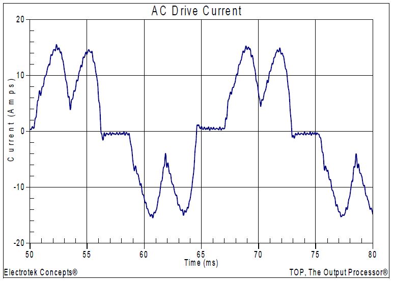
Figure 8 shows the simulated line-to-line voltage at the inverter terminals for the basecase conditions. The dc voltage for the drive was approximately 650 V. The inverter switching frequency (Fs) for the case was 675 Hz and the motor frequency was 45 Hz.
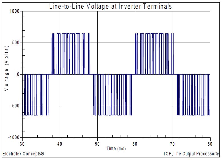
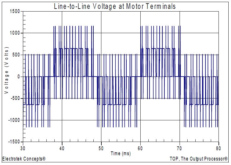
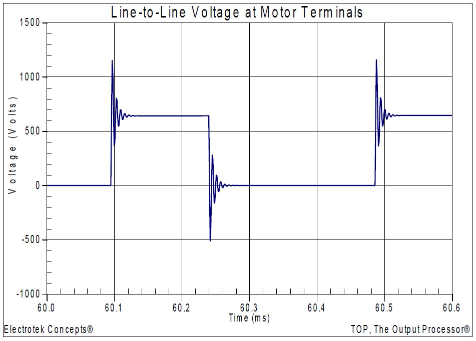
Figure 9 shows the simulated line-to-line voltage at the motor terminals for the case with no mitigation added. Figure 10 shows an expanded view of the waveform highlighting several of the ringing transients. The peak simulated transient voltage was 1,153V, which was approximately 1.77 per-unit (similar to the measured waveform previously shown in Figure 6).
The second simulation case (Case 4b) evaluated the power conditioning alternative of adding a series choke between the inverter and the induction motor. Inductive chokes (a.k.a., reactors) are similar to isolation transformers, except that they do not define a separately derived system. Inductive chokes provide additional impedance in the circuit in much the same manner that an isolation transformer does, but at a much-reduced cost.
Chokes are often applied to the front-end of adjustable-speed drives to protect the drives from nuisance tripping caused by utility capacitor bank switching and other normal power system switching operations. Some drive manufacturers now produce drives with chokes as part of their standard design. Chokes also help prevent voltage notching, caused by power electronic switching, from disturbing other sensitive customer equipment. They can limit notching to the drive side of the inductive choke.
Figure 11 shows the simulated line-to-line voltage at the induction motor terminals for the case with a 5% choke added between the inverter and motor terminals. Generally, a choke is specified in %X and hp. The inductance of the simulated choke rating was approximated using the following expression:
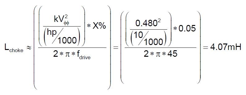
where:
fdrive = inverter output fundamental frequency (Hz)
X = inductive reactance of choke (%)
kVϕϕ = system rms phase-to-phase voltage (kV)
hp = horsepower rating of the motor (hp)
The resulting transient voltages at the motor terminals were significantly reduced with the 5% choke. It should be noted that the fundamental drive frequency voltage was somewhat lower due to the voltage drop across the choke.
The final simulation case (Case 4c) evaluated the power conditioning alternative of adding a motor terminal filter to the induction motor. A motor terminal filter is a type of low-pass filter that passes signals with low frequencies and reject signals with high frequencies. These filters can improve power quality by reducing the effect of the transient energy and by removing noise from the electrical system. Low-pass filters can be used to provide even better protection than inductive reactors for high frequency transients.
A first-order filter consisting of a capacitor in series with a resistor can be designed to have minimal losses and to match the surge impedance of the cable that supplies the motor.
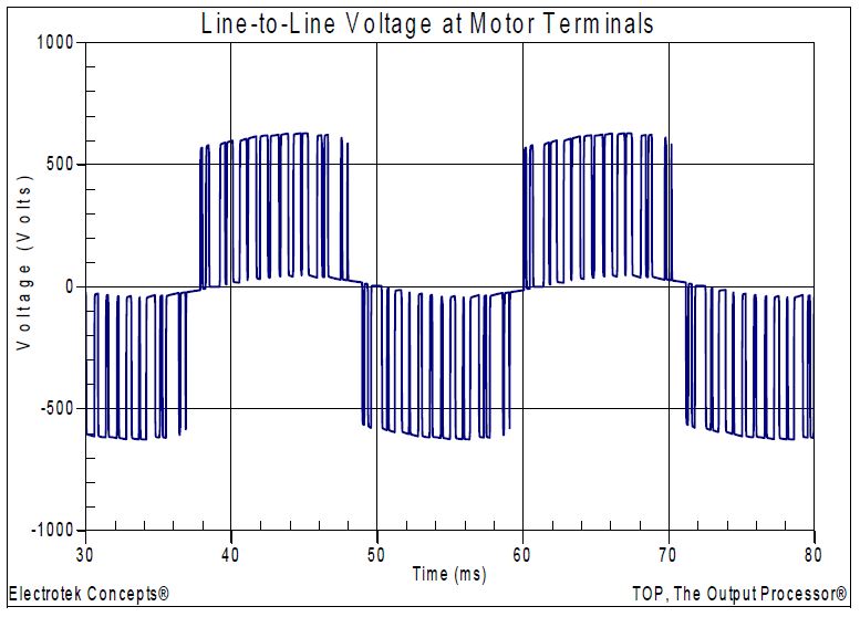
Figure 12 shows the simulated line-to-line voltage at the induction motor terminals for the case with a shunt motor terminal filter added at the motor terminals. The simulated filter component values were 1μF (capacitor) and 100Ω (resistor). The transient voltages were significantly reduced with the motor terminal filter, as compared with the basecase conditions. It should be noted that there was no fundamental drive frequency voltage drop for this case because the filter was connected in shunt, rather than in series like the previous case.
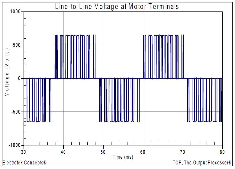
Figure 13 shows an expanded view of the simulated line-to-line voltages at the motor terminals for the three simulated cases. The figure illustrates the reduced transient voltages with the mitigation alternatives and the voltage drop for the 5% series choke case (Case 4b).
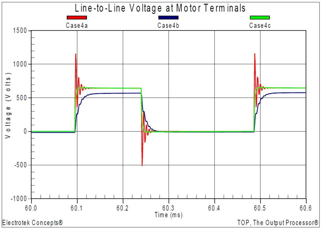
Figure 13 – Simulated Line-to-Line Motor Voltage Waveforms
SUMMARY
This case study presented a customer adjustable-speed drive motor winding failure analysis. The study investigated the potential for severe high frequency transient overvoltages at induction motor terminals for an adjustable-speed drive that utilized a pulse-width modulation inverter, along with a significant length of cable between the inverter and motor.
In the past, the inverters for many drives were thyristor based with either forced-commutation or loadcommutation. For current source inverter (CSI) drives based on thyristor or gate turn-off (GTO) devices, the inverter switching frequency was limited to several hundred Hz. This low switching frequency means that these devices have relatively high commutation losses and need a relatively long commutation period. Consequently, induction motors supplied from current source inverter drives have a lower probability of experiencing fast-front transient voltages.
In an effort to improve the efficiency of many industrial processes, standard induction motors have been retrofitted with adjustable speed drives. The drives allow for better speed control, soft starting of motors, and increased efficiency of the overall process operation. Unfortunately, there can also be some power quality-related drawbacks when using these drives.
A number of drive manufacturers are working with motor manufacturers to match drive-duty induction motors to their adjustable-speed drives. The adjustable-speed drive and motor are provided as a complete package. The induction motors are designed to withstand the severe duties imposed on them by the high switching frequencies of the PWM inverters.
This case study investigated one of potential problems with applying new adjustable-speed drives with older induction motors, which is motor winding failure due to transient overvoltages. The power conditioning solutions that were evaluated included series chokes and shunt motor terminal filters. Other potential solutions include changing the cable length, which is generally not practical for the customer; and changing the inverter switching frequency, which may also not be practical and may not significantly reduce the transient overvoltages.
REFERENCES
- IEEE Recommended Practice for Monitoring Electric Power Quality,” IEEE Std. 1159-1995, IEEE, October 1995, ISBN: 1-55937-549-3.
- IEEE Recommended Practice for Emergency & Standby Power Systems for Industrial & Commercial Applications (IEEE Orange Book, Std. 446-1995), IEEE, ISBN: 1559375981.
- IEEE Recommended Practice for Powering and Grounding Electronic Equipment (IEEE Emerald Book, Std. 1100-1999), IEEE, ISBN: 0738116602.
- Melhorn, C.J., and Tang, L., “Transient Effects of PWM Drives on Induction Motors,” IEEE Transactions on Industry Applications, Volume 33, Issue 4, pp. 1065-1072, Jul/Aug 1997.
- R.C. Dugan, M.F. McGranaghan, S. Santoso, H.W. Beaty, “Electrical Power Systems Quality,” McGraw-Hill Companies, Inc., November 2002, ISBN 0-07-138622-X.
RELATED STANDARDS
IEEE Std. 1159, IEEE Std. 1100, IEEE Std. 446, ANSI Std. C84.1
GLOSSARY AND ACRONYMS
ASD: Adjustable-Speed Drive
CF: Crest Factor
DPF: Displacement Power Factor
PF: Power Factor
PWM: Pulse Width Modulation
THD: Total Harmonic Distortion
TPF: True Power Factor
