Published by Electrotek Concepts, Inc., PQSoft Case Study: Evaluation of Capacitor Bank Switch Restrikes, Document ID: PQS0606, Date: April 1, 2006.
Abstract: The analysis of high voltage capacitor switching consists primarily of measurements and computer simulations. There are a number of important transient related concerns when transmission and distribution voltage level capacitor banks are applied, including insulation withstand level, switchgear capabilities, energy duties of protective devices, and system harmonic considerations. The considerations should also be extended to include distribution systems and sensitive customer equipment. This case study presents methods for determining transient overvoltage and arrester duties and during capacitor switch restrike events and sample simulation and field measurements of restrike waveforms.
CAPACITOR BANK RESTRIKE EVENTS
A capacitor switching device de-energizes a capacitor bank at a current zero (refer to Figure 1). Since the current is capacitive, the voltage at the time of current interruption is at a system peak. Successful interruption depends on whether the switch can develop sufficient dielectric strength to withstand the rate-of-rise and the peak recovery voltage. For a grounded-wye capacitor bank, two times (2 per-unit) the system voltage will appear across the switch contracts one-half cycle after interruption. If the switch cannot withstand this recovery voltage, the switch will restrike.
Determining Transient Overvoltages and Arrester Duties
The energy duty requirements for arresters at capacitor bank locations depend on the size of the capacitor and on existing arresters located at the substation. In general, the most severe duty for an arrester near a capacitor bank occurs during a switch restrike. This is due to the trapped charge on the capacitor at the instant the restrike occurs, and results in a greater magnitude of the voltage oscillation.
It is also important to consider the coordination of MOV arresters (at the capacitor location) with any conventional gapped type arresters in the substation. It is important that the protective level of the MOV arresters be low enough to prevent operation of the gapped arresters. This is often difficult to achieve. If coordination is not possible, there are three options for arrester protection at the substation involved:
- Replace all of the gapped type arresters in the substation with MOV arresters. The arresters will share the energy duty in the event of a restrike and there should be no danger of arrester failure.
- Add one set of MOV arresters. This will greatly decrease the probability that a conventional arrester will fail during a capacitor restrike event because the MOV arrester will reduce the chance of a conventional arrester sparkover. The minimum size MOV should be used for best coordination with existing arresters.
- Use only conventional gapped type arresters at the substation. This option relies on the integrity of the capacitor switch to prevent a restrike event. If a restrike would occur, it is unlikely the conventional arresters would be able to withstand the associated energy duty.
The arrester energy during a restrike depends on the following parameters:
− Capacitor configuration (grounded vs. ungrounded)
− Capacitor size
− Existence of other parallel capacitors
− Source strength
− Number of lines leaving substation
− Nearby capacitor banks
− Arrester protective level
Arrester applications at large shunt capacitor banks need to be evaluated carefully due to the high-energy duties that can occur in the event of a restrike in the capacitor switch. The energy levels will depend on whether the capacitor bank is grounded or ungrounded.

During normal grounded-wye capacitor bank de-energization, the capacitor current is interrupted at the peak system voltage thus leaving a 1.0 per-unit trapped charge on the capacitor. This trapped charge results in an offset in the transient recovery voltage (TRV) that reaches a magnitude of 2.0 per unit one-half cycle after opening. Significant transient voltages can occur if the switch restrikes during clearing. The worst restrike transient occurs when twice the normal system peak voltage appears across the switch contacts. Theoretically, in this case, the magnitude of the transient voltage approaches 3.0 per unit.
Ungrounded-wye capacitor banks may expose the capacitor switch to recovery voltages greater than 2.0 per unit. Recovery voltages may reach 2.5 per unit on the first phase to open when the other phases open at the next current zero. If two of the phases delay opening, the recovery voltage may reach 3.0 per unit on the first phase to open. Finally, if one of the other phases delays, the transient recovery voltage would be 4.1 per unit. If a restrike occurs on the first phase to open at 2.5 per unit, a recovery voltage of 6.4 per unit can occur on one of the other two phases because of the voltage that builds up across the neutral capacitance. The high recovery voltage on another phase can cause a second restrike, resulting in a two-phase restrike.
The transient voltages on a capacitor bank and the recovery voltages across the switch can be reduced by installing arresters on the capacitor side of the switching device. If the switch is rated for the recovery voltages involved, then the arresters can be located on either the capacitor side or source side of the switch.
To evaluate arrester energy duty, simple expressions can be derived for grounded and ungrounded capacitor banks in terms of capacitor size, source inductance, peak system voltage, and arrester protective levels. The equations for evaluating the energy duty are given in
Table 1 – Arrester Duty during a Capacitor Restrike

Assuming a given capacitor bank rating, the arrester energy duty (in joules) versus the arrester protective level can be determined. Figure 2 and Figure 3 illustrate the arrester duty for Metal-Oxide Varistors (MOV). Silicon-Carbide (SiC) arresters generally have more severe energy duties because of the partial capacitor discharge that occurs when the arrester sparks over.

(per-unit of normal peak line-to-neutral voltage)

(per-unit of normal peak line-to-neutral voltage)
While the placement of an MOV arrester on the capacitor side of the breaker is not required, it is generally recommended. This location provides overvoltage protection for the bank itself, as well as limiting the recovery voltage seen by the breaker. Another benefit of the arrester is that its presence should help to minimize the possibility of multiple restrike events. Previous experience has indicated that if a breaker experiences multiple restrikes during clearing, equipment failure will more than likely occur.
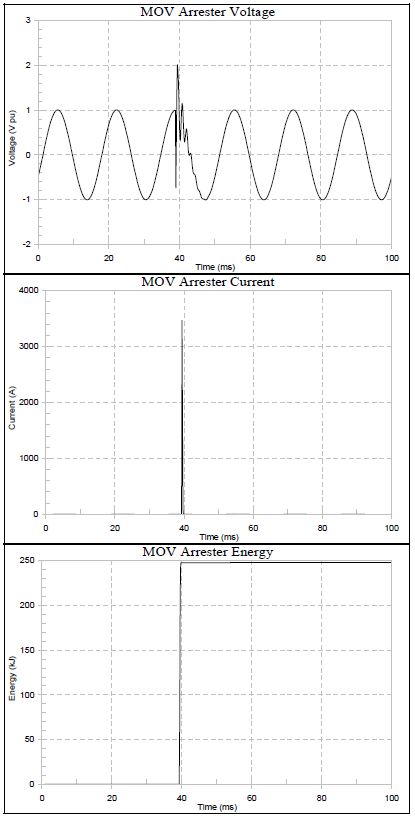
Figure 4 illustrates an example of a computer simulation showing arrester (MOV) voltage, arrester current, and arrester energy duty during a capacitor switch restrike.
Sample Simulations and Field Measurements of Restike Events
Figure 5 shows the bus voltage (in per-unit) during a multiple restrike event on a 50 MVAr, 230kV transmission capacitor bank. The capacitor bank is protected with an 180kV MOV arrester.
Figure 6 shows the bus voltage during de-energization and switch restrike of a 161kV transmission capacitor bank. The worst-case transient voltage was approximately 2.02 per-unit (202%).

Figure 7 shows the bus voltage during a multiple restrike event on a 34.5kV capacitor bank. The worst-case transient voltage was approximately 1.55 per-unit (155%).

Figure 8 shows the transformer secondary current during a multiple restrike event on a 34.5kV capacitor bank.
SUMMARY
Arrester energy during a capacitor switch restrike event is dependent on the capacitor configuration, ratings, source strength (including nearby capacitors and number of transmission lines), and arrester protective level (e.g., maximum switching surge protective level – MSSPL).
A properly sized MOV arrester, placed between a capacitor switch and a capacitor bank, will provide overvoltage protection for a single restrike event. In addition, the arrester will protect the bank from excessive overvoltages, as well as reduce the likelihood of multiple restrike events that can result in equipment failure.
REFERENCES
G. Hensley, T. Singh, M. Samotyj, M. McGranaghan, and T. Grebe, Impact of Utility Switched Capacitors on Customer Systems Part II – Adjustable Speed Drive Concerns, IEEE Transactions PWRD, pp. 1623-1628, October, 1991.
G. Hensley, T. Singh, M. Samotyj, M. McGranaghan, and R. Zavadil, Impact of Utility Switched Capacitors on Customer Systems – Magnification at Low Voltage Capacitors, IEEE Transactions PWRD, pp. 862-868, April, 1992.
T.E. Grebe, Application of Distribution System Capacitor Banks and Their Impact on Power Quality, 1995 Rural Electric Power Conference, Nashville, Tennessee, April 30-May 2, 1995.
M. McGranaghan, W.E. Reid, S. Law, and D. Gresham, Overvoltage Protection of Shunt Capacitor Banks Using MOV Arresters, IEEE Transactions PAS, Vol. 104, No. 8, pp. 2326-2336, August, 1984.
S. Mikhail and M. McGranaghan, Evaluation of Switching Concerns Associated with 345 kV Shunt Capacitor Applications, IEEE Transactions PAS, Vol. 106, No. 4, pp. 221-230, April, 1986.
T.E. Grebe, Technologies for Transient Voltage Control During Switching of Transmission and Distribution Capacitor Banks, 1995 International Conference on Power Systems Transients, September 3-7, 1995, Lisbon, Portugal.
Electrotek Concepts, Inc., An Assessment of Distribution System Power Quality – Volume 2: Statistical Summary Report, Final Report, EPRI TR-106294-V2, EPRI RP 3098-01, May 1996.
Electrotek Concepts, Inc., Evaluation of Distribution Capacitor Switching Concerns, Final Report, EPRI TR-107332, October 1997.
RELATED STANDARDS
IEEE Std. 1036
GLOSSARY AND ACRONYMS
MOV: Metal Oxide Varistor Arrester
MSSPL: Maximum Switching Surge Protective Level
SiC: Silicon Carbide Arrester
TRV: Transient Recovery Voltage
