Published by Sohel UDDIN1, Hussain SHAREEF1, Azah MOHAMED1, M A HANNAN1
Dept. of Electrical, Electronic & Systems Engineering (1), Universiti Kebangsaan Malaysia (1)
Abstract. The purpose of this paper is to investigate harmonic generation from dimmable Light Emitting Diode lamps (LEDs) which are used in residential and commercial applications as an energy efficient lighting systems. It is done by conducting laboratory tests on various LED lamps and tapping the load current behavior under different conditions. Then the frequency domain analysis is performed to investigate the generated harmonics. Harmonic levels of different wattage, various branded dimmable and non dimmable LED bulbs along with dimmable compact fluorescent lamps are experimentally evaluated and compared. Experimental result shows that, all LED lamps generate very high level of harmonic during dimming operation which may affect the power quality of AC mains.
Streszczenie. W artykule opisano zagadnienie emisji harmonicznych przez ściemnianą diodę LED, wykorzystywaną do oświetlania pomieszczeń. Przeprowadzono próby laboratoryjne w różnych warunkach pracy, a na ich podstawie analizy generowanych harmonicznych. Pod tym kątem dokonano porównania działania badanych diod z innymi energooszczędnymi rozwiązaniami (diody LED nieściemniane, świetlówki). (Analiza generacji harmonicznych przez ściemniane lampy z diodami LED).
Keywords: Light Emitting Diodes (LEDs), Compact Fluorescent Lamps (CFLs), Dimmable Function, Total Harmonic Distortion (THD), Słowa kluczowe: LED, CFL, świetlówki, funkcja ściemniania, THD, jakość energii.
Introduction
It is estimated that lighting accounts 20% of the electricity demand globally. Incandescent lamp has been the main source of lighting industry over 100 years. However, incandescent lamp produces insufficient lumens and generates high heat. Therefore to promote energy saving, many countries already banned energy inefficient incandescent light bulbs and replace it with other lighting technologies like light emitting diode (LED) lamps and compact fluorescent lamp (CFL) technology [1-2]. With technological advancement in semiconductors, LEDs are evolving in lighting industry because of their special features like power saving, environmental friendliness, dimmable and multi color features of solid state lighting system. However, a single LED is not sufficient to emit light like incandescent bulbs due to point source nature of LEDs and current concentration. Therefore a multi LED system is introduced where several LEDs are connected in series, parallel or series-parallel combinations [1] to produce dispersed light like in conventional bulbs.
In addition, dimming control is required to regulate lighting levels for human needs as well as reduction of electricity demand, visual comfort and better productivity at work place [2]. Besides, for architectural lighting systems, dimming is essential to fulfill the aesthetic requirements of a space. An analysis done by the lighting research centre shows that 6% of energy can be saved by individually controlling manual dimmers [2]. Rand et al. also reported that, daylight harvesting and light dimming can save around 30-40% of energy [3] by using traditional dimmable lighting source like incandescent lamps, fluorescent lamps. But rapid development of semiconductor technology, LED is showing promising dimmable characteristic. Mainly in all domestic LED light dimming systems, phase-cut (triac dimmer) control technique is used in which the current is switch on only for a certain period of the line cycle. In most schemes of phase control dimmer, amplitude modulation (AM) or pulse width modulation (PWM) are used [4-5]. In AM method, reduction of current can cause degradation of light illumination. On the other hand, PWM allow control in light output by changing duty cycle. However, a PWM controller connected in series with each LED string can increase circuit complexity and reduces life time of LED lamps [6]. Infect, due to fast response of LEDs and their drivers, most of the LED lamps cannot perform properly with the Triac dimmer [3]. To overcome this drawback many researchers design special driver which are compatible with Triac dimmer [7-10]. In the work of Lianghui, a primary side control single stage flyback converter with a dimmer is proposed [7]. The author realized the input voltage feedback with phase angle in primary side and hence there is no need of secondary side feedback current and the circuit become simple and increases the reliability. However, due to current chopping in dimmable ballasts, they may create harmonic distortion on the feeders. The deviation of waveform from perfect sinusoid is usually expressed in terms of harmonic distortion of the current and voltage waveforms. Normally, LED lamps creates harmonic. In addition with dimmer function, this harmonic may increase drastically because current drawn by these lamps has more deviation from sinusoidal wave shape. In the field of LED lamp research, a few contributions focus on harmonic emissions of conventional LEDs lamps [11-12]. But almost nothing is done about harmonic from dimmable LED lamps. In spite some contribution of harmonic is done with dimmable CFLs [13].
This paper presents some analysis on harmonic generation from dimmable LED lamps. This is characterized by measurement tests, using various available dimmable LED bulbs. In the investigations, laboratory tests are conducted for this purpose with 3 Watt and10 Watt LED lamps with dimming function from different manufactures. All tests are carried out to observe their current and voltage waveforms and analyze them in terms of power rating, and brands. The test results are also compared with IEC 61000-3-2 harmonic standard and harmonics from dimmable CFLs.
Basic operation of LED lamps and its harmonic standards
The principle operation behind LED bulbs and the harmonic emission limits for LEDs as defined by IEC 61000-3-2 are discussed in this section.
Operating Principal of LED Lamps
LEDs require a constant current source from a low DC voltage source, obtained from the AC mains. Therefore, it is necessary to use a converter to regulate the voltage and control the current applied to the LEDs. The buck, boost, flyback and resonant converters are well known in literature as a power source to the LEDs [14-15].
Fig. 1 depicts a block diagram of typical low-wattage LED ballast with dimming control. It includes the AC line input voltage, typically 220-240 VAC 50/60 Hz, an EMI filter to block circuit-generated switching noise, a dimmable control circuit, a rectifier with smoothing capacitor, a PWM controlled constant current source converter for DC to DC conversion and an array of LEDs. Moreover, the input current can be changed by the dimmer circuit to vary light output. Since the rated load powers are low in LED lamps, the directives governing the injection of harmonics are not particularly strict [16] and therefore power factor control
circuits may or may not be found in low-wattage LED lamp ballasts. However, to reduce the generated harmonics and to improve the power factor it is possible to introduce either an input passive filter, valley filled circuits, IC controlled active filtering configurations.

Harmonic Injection Limits for LED Lamps
Similar to any other appliance, LED lamps also must comply with several directives which are applicable to the product. The IEC 61000-3-2 standard assesses and sets the limit for equipment that draws input current ≤16A per phase [17-18]. Harmonic emission limits for lamps are subdivided based on their active power up to 25W and above in class C. Lamps having an active input power less than or equal to 25W must satisfy at least one out of the two following criterions. One of the criteria is that the third harmonic current should not exceed 86% of the fundamental and the fifth harmonic current should not exceed 61%. That gives the value of the current THD approximately 105%. The recommended voltage distortion limit for class C equipment is 3% and 5% for individual harmonics and total harmonic distortion (THDV) respectively.
The other criterion is given as a Table 1 for each harmonic order.
Table 1. IEC 61000-3-2 limits for class C equipment (P ≤ 25W)
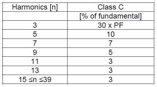
Table 2. Technical data for tested LED lamps

Methodology
To analyze the characteristics of the LED lamps with dimming function, 5 samples of with different power ratings from various manufacturers as shown in Table 2 were tested. The lamps have build in ballast which is powered using E-27, E-14 or GU-10 type sockets, commonly available in retail stores. All the tested lamps are designed to operate at 220-240 V and have power consumptions rating of 3 W to 10 W.

To obtain accurate data concerning the exact current harmonic content of LED bulbs, an experimental setup as shown in Fig. 2 is assembled. It consists of four components namely, Fluke 434 power quality analyzer, Fluke i30s current clamp, LED bulb(s) under test, and a personal computer to analyze the signals. Each lamp is kept switched on for 10 minutes before the measurements are taken for stabilization. Each lamp is tested for four times to eliminate any error during different period of the day. Furthermore, for comparisons purposes, a sample of dimmable CFLs indicated in Table 2 are also tested using the same procedure. The captured current waveforms were analyzed by using Fluke 434 power quality analyser and MATLAB software where the current waveforms of the lamps were transformed using the Fourier Theorem. It provide frequency spectrum of the lamp currents
represented by the fundamental sinusoidal component and a series of higher order harmonic components at frequencies that are integer multiples of the fundamental frequency as in (1).

Where I(t) is the input current, In is the harmonic current component of order n. Io is the average current. Furthermore, the square roots of the sum of the amplitudes of the harmonic as in (2) are used to represent the total harmonic distortion (THD).
Where I1 is the rms (Route mean square) value of fundamental current and In is the harmonic current component of order n.
Experimental analysis
In this section, measurements of various dimmable LED lamp test were assessed to investigate the harmonic generation when the brightness of the lamps are varied using a Triac dimmer controller commonly used in indo lighting controls. For this findings from the tested lamps at dimming and non dimming mode are analyzed and discussed first. Then a performance comparison of different dimmable LED lamps from various manufactures is conducted. Furthermore, a comparison of dimmable LED and CFL lamps carried out.
General findings from dimmable LED lamps
In order to understand the harmonic patterns of dimmable LED lamps, we consider an Osram 10 W dimmable bulb. The current and voltage wave shape is shown in Fig. 3(a) when it is operated at 0° firing angle of the Triac dimmer representing full brightness of the lamp. From the figure it can be noted that the current waveform is not sinusoidal even at full brightness where the dimmer is not yet activated. It means that this bulb creates and inject harmonic into the power system. However, it is clear from Fig. 3(a), that the voltage wave shape is pure sinusoidal. Therefore only current is distorted. To further investigate, the corresponding harmonic spectrum at 0° firing angle or at non dimming mode Fig. 3(b) plotted. It is noticed that the magnitude of harmonic current decreases with increased harmonic order.

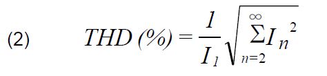
In order to observe the effect of reducing brightness on current harmonics, the dimming angle is increased from 0° to 45°, 90° and 135° respectively. As shown in Fig. 4, it is found that increasing the firing angle of the dimmer, the current drawn by the lamp is more chopped and deviates further from sinusoidal pattern although the magnitude of the current decreases. As a result, harmonic level is increased as depicted in Fig. 5. As seen in Fig. 5, this lamp creates a THDI value of 65%-70% at 0° firing angle (full brightness) whereas it becomes 76%-80% and 230%-235% at 45°and 90° respectively. This increase in THDI may be due to dimming control switch which contribute some additional harmonics.
Findings from Same Wattage LED Lamps
These tests aim to identify the harmonic levels from same wattage lamps introduced by different manufacturers. For this purpose 3 Watt bulbs were investigated. Fig. 6 depicts the wave forms obtained from 3 Watt LED lamps from Philips and Aira brand with 0° delay angles.
From Fig. 6, it is clear that the current wave shape is totally different from Osram 10 Watt bulb because different manufacturers used different type of ballast circuit inside the bulb. The harmonic patterns at various dimming levels of these lamps are shown in Tables 3 and Table 4. For the case of Phillips 3 Watt lamp, it is observed that there is a very large variation of harmonic between 0° and 135°. These harmonic levels are not acceptable for IEC 61000-3-2 standard.


Table 3. Harmonic Content of Philips 3 W with Several Dimming Mode

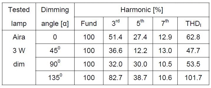
However in the case of Aira brand 3 Watt dimmable lamp, it shows a different characteristic in which harmonic level decrease with decreasing brightness as shown in Table 4. This may be due to the rectangular shape characteristics of the current wave it maintain during the operation. From Fig. 6 it is also clear that the current peaks observed for the case of Aira lamp is much lower than that required by Philips lamp. These high peaks introduce more harmonics into the system. Fig. 7 ill starred current characteristic and harmonic spectrum of those same lamps as discussed in fig. 6 but 45° delay angles.
Table 4. Harmonic Content of Aira 3 W with Several Dimming Mode

Findings from Same wattage dimmable and non dimmable LED Lamps
The third test investigates the effect of harmonic characteristics of dimmable LED lamps with conventional LED bulbs having same power ratings. For this purpose, 10 Watt normal LED lamp and 10 Watt dimmable LED lamp from Osram as mentioned in Table 2 is compared. Fig. 8 shows the current waveforms along with their harmonic levels for these two lamps at full brightness. From the figure it can be reviled that the distortion level of dimmable LEDs is lower than normal LED lamp at full brightness. However, in case of dimmable bulb, the distortion levels increases rapidly with reduction of brightness. As a result, dimmable lamp at lower brightness is more problematic than conventional LED bulbs.

Comparison with Dimmable CFLs
Since CFLs are the most commonly used energy efficient lamps today, it is important to compare the performance of new dimmable LED lamps with dimmable CFLs in terms of harmonic generation. For this purpose, Osram brand 20 Watt LED dimmable lamps are compared with 20 Watt dimmable CFLs from same manufacturer. Currently, there is no 20 Watt dimmable LED bulb available in the market so two 10 Watt bulbs of same model is used in parallel for this purpose. This 20 Watt combination gives the same characteristics of 10 Watt LED bulbs. In fact, 20 Watt combination gives a little less harmonic than 10 Watt LED bulb alone.

Table 5. Harmonic Content of Osram 20 W (Leds and Cfls) Lamps with Several Dimming Mode

Fig. 9 depicts the experimental result of current characteristic for Osram 20 Watt dimmable LED and Osram 20 Watt dimmable CFL lamps for 10 cycles at 0° delay angle. From the figure it is clear that the current wave shapes are totally different due to different ballast circuit and the current peak of CFL is almost double to that of LED lamp. A side from current peaks, it is understood from Table 5 that CFL lamp performs better at low brightness but at full brightness LED creates less harmonic.
Conclusion
This paper has presented several experimental results on harmonic generation from dimmable LED lamps that are currently being used for domestic and commercial lighting. In the experiments various types of dimmable LED lamps from different manufactures were tested to evaluate their harmonic performance in terms of power rating, brand, type of ballast used. Furthermore a comparison of harmonic contents of LED lamps and CFLs were also made at dimming mode. Also a comparison of dimmable LED lamps with normal LED lamps in term of harmonic was discussed. Experimental results show that both types of LEDs produce harmonics and increase the value of current total harmonic distortion (THDI) due to the use of power electronic converter as a ballast to drive LED arrays in the bulbs. The value of THDI ranges between 47 % and 360 % for dimmable LEDs bulbs. Moreover, normal LED lamps generate lower harmonic than dimmable ones. Dimmable CFLs also shows similar characteristic like LED counterparts. It is also noted that harmonic characteristics of LED lamps and CFLs of equivalent wattage either at dimmable or non dimmable mode from same vendor depend on the type of ballast used. It is also noted that
different manufactures of LED lamps use diverse ballast technologies. Currently there is no standard for dimmable lamps and it is recommended that an individual standard should employ for dimmable operation.
Acknowledgment
This work was carried out with the financial support from the Ministry of Higher Education of Malaysia (MOHE) under the research grant UKM-KK-02-FRGS0193-2010.
REFERENCES
[1] Pinto R.A., Cosetin M.R., Marchesan T.B., Silva M.F.D., Denardin G.W., Fraytag J., Campos A., Prado R.N.D., Design procedure for a compact lamp using high-intensity LEDs, 35th Annual Conference of IEEE Industrial Electronics, (2009), 3506-3511
[2] Leslie R., Raghavan R., Howlett O., Eaton C., The potential of simplified concepts for daylight harvesting, Lighting Research and Technology, 37 (2005), No. 1, 21-38
[3] Rand D., Lehman B., Shteynberg A., Issues, models and solutions for triac modulated phase dimming of LED lamps, IEEE Power Electronics Specialists Conference, (2007), 1398- 1404
[4] Huang H.M., Twu S.H., Cheng S.J., Chiu H.J., A single-stage SEPIC PFC converter for multiple lighting LED lamps, 4th IEEE International Symposium on Electronic Design, Test and Applications, (2008), 15-19
[5] Hu Y., Jovanovic M.M., LED driver with self-adaptive drive voltage, IEEE Trans. Power Electron, 23 (2008), No. 6, 3116-3125
[6] Chiu H.J., Lo Y.K., Chen J.T., Cheng S,J,, Lin C,Y,, Mou S.C., A high-efficiency dimmable LED driver for low-power lighting applications, IEEE Trans. Industrial Electronics, 57 (2010), No.2, 735-743
[7] Xu L., Zeng H., Zhang J., Qian Z., A primary side controlled WLED driver compatible with triac dimmer, 26th Annual IEEE Applied Power Electronics Conference and Exposition, (2011), 699-704
[8] Xu X., Wu X., High dimming ratio LED driver with fast transient
boost converter, IEEE Power Electronics Specialists Conference, (2008), 4192-4195
[9] Garcia J., Calleja A.J., Corominas E.L., Gacio D., Campa L., Díaz R.E., Integrated off-line ballast for high brightness LEDs with dimming capability, Journal of Circuits and Systems, 2 (2011), No. 4, 338-351
[10] Borekci S., Dimming electronic ballasts without striations, IEEE Trans. Industrial Electronics, 56 (2009), No. 7, 2464-2468
[11] Cuk V., Cobben J.F.G., Kling W.L., Timens R.B., An analysis of diversity factors applied to harmonic emission limits for energy saving lamps, 14th Intel Conference on Harmonics and Quality of Power, (2010), 1-6
[12] Watson N.R., Scott T.L., Hirsch S.J.J., Implications for distribution networks of high penetration of compact fluorescent lamps, IEEE Trans. Power Delivery, 24 (2009), No. 3, 1521- 1528
[13] Mohamed K., Shareef H., Mohamed A., Analysis of harmonic emission from dimmable compact fluorescent lamps, International Conference on Electrical Engineering and Informatics, (2011), 1-5
[14] Qu X., Wong S.C., Tse C.K., Resonance-assisted buck converter for offline driving of power LED replacement lamps, IEEE Trans. Power Electronics, 26 (2011) No. 2, 532-540
[15] Zhou K., Zhang J.G., Yuvarajan S.A., Weng D.F., Quasi-active power factor correction circuit for HB LED driver, IEEE Trans. Power Electronics, 23 (2008) No. 3, 1410-1415
[16] Shareef H., Mohamed A., Marzuki N., Analysis of ride through capability of low-wattage fluorescent lamps during voltage sags, International Review of Electrical Engineering, 4 (2009), No. 5, 1093-1101.
[17] IEEE Std 519-1992, Recommended Practices and Requirements for Harmonic Control in Electrical Power Systems, (The Institute of Electrical and Electronics Engineers, 1993)
[18] IEC Std 61000-3-2, Limits for Harmonic Current Emissions (Equipment Input Current ≤ 16A Per Phase), (Ed. 3.2, 2009)
Authors: Sohel Uddin is a Masters student at the Department of Electrical, Electronic and Systems Engineering, Universiti Kebangsaan Malaysia (UKM), E-mail: sohel_091@yahoo.com.
Dr. Hussain Shareef is a senior lecturer of Department of Electrical, Electronic and Systems Engineering, Universiti Kebangsaan Malaysia (UKM), E-mail: shareef@eng.ukm.my.
Prof. Dr. Azah Mohamed is a professor of Department of Electrical, Electronic and Systems Engineering, Universiti Kebangsaan Malaysia (UKM), E-mail: azah@eng.ukm.my.
Dr. M A Hannan is an Associate professor of Department of Electrical, Electronic and Systems Engineering, Universiti Kebangsaan Malaysia (UKM), E-mail: hannan@eng.ukm.m
Source & Publisher Item Identifier: PRZEGLĄD ELEKTROTECHNICZNY, ISSN 0033-2097, R. 89 NR 4/2013
