– A Case Study
Published by V. S. Jape#1, D. S. Bankar*2, Tejaswini Sarwade#3
Electrical Engineering1, Electrical Engineering2, Electrical Engineering3, BVDU Pune1, BVDU Pune2, SPPU Pune3
1jape_swati@yahoo.co.in , 2dsbankar@bvucoep.edu.in , 3sarwadet@gmail.com
Abstract — Tracking of system overall performance in phrases of Power Quality disturbances and its ill effects on distribution network is growing attention of application towards tracking of Power Quality indices like voltage sag, voltage swell, and harmonics. The paper introduces new index as Power Quality Distortion Index (DI) which offers the contribution of every load on the total distortion of the power system. Presented system set the basis of tracking and analysis of Power Quality indices for distribution network. The characterization of Power Quality problems is found through non-widespread currents, voltages and frequencies. The Power Quality is related to variations of supply voltage in the form of sags, swells, harmonics, transients, and so on. These troubles outcomes in deterioration of energy deliver to end customers, technology of various disturbances. The loads used by consumers also account for deterioration of Power Quality. Penalties are charged for low power factor loads but at the same time negligence to sizable existence of Power Quality parameters issues like voltage sags and harmonic distortions. Introduction of Custom Power Devices (CPD) is an effective solution over Power Quality problems in distribution network. Paper presents diverse Power Quality indices like Distortion Index as the computational parameter of Power Quality and design of Dynamic Voltage Restorer (DVR) to compensate voltage sag in the system. Effect of DVR on Distortion Index (DI) is also observed and outcomes are analyzed with the assist of MATLAB/SIMULINK.
Keywords — Power Quality, Harmonics, Custom Power Devices (CPD), Dynamic Voltage Restorer (DVR), Distortion Index (DI)
I. INTRODUCTION
The power system layout has become extra complicated every day. It comprises numerous generating stations and loads whose interconnection is through numerous transmission and distribution strains. Also, multiplied use of power electronics based, plc primarily based circuit’s outcomes into growth in nonlinearity. These sorts of loads are sensitive to Power Quality parameters including voltage sags, swells, harmonics, sparkles, fluctuations, etc.
Existence of harmonic distortion is due to deviation in voltage, current or fundamental frequency. The voltage sag is a drop off in root mean square value of voltage or current usually between 0.1 per unit to 0.9 per unit at power frequency lasting for half cycle to 60 seconds. Fault clearing time refers the variety of 3 to 30 cycles [1].voltage swell is rise in root mean square value of voltage at power frequency between 1.1 per unit to 1.8 per unit lasting for half cycle to 60 seconds. Transients are the part of change within the variable disappears in the course of alteration from one consistent state to every other.
II. POWER QUALITY IMPROVEMENT
Enhancement in efficiency of power system desires continuous working which in addition attributes the importance of monitoring for any form of disturbances that’s to be taken into consideration as Power Quality issues and also offer corrective measures on such problems to restrict the occurrences of those events. Mitigation of Power Quality problems is difficult with the aid of the use of traditional equipments including tap changing transformers, lightning arresters, surge arresters, capacitor banks, and many others. Also existence of power electronics devices performs a vital role to decide performance of PQ issues. Power Electronics primarily based solutions are specially categorized as FACTS Controllers for transmission systems and Custom Power Devices (CPDs) which contributes fundamental function in Power Quality improvement of distribution network. Various CPDs are available consisting of Distribution Static Compensators (D-STATCOM), Active Power Filters (APF), Dynamic Voltage Restorer (DVR), Battery Energy Storage Systems (BESS), Static VAr Compensators (SVC), and so on. Dynamic Voltage Restorer (DVR) is identified as more efficient device among of all devices.
A. Control Methods of DVR
Control of DVR circuit topology is critical element for design and modelling factor of view, which includes voltage disturbances identification with proper recognition strategies. Voltage supply converter at once impacts DVR overall performance because it satisfies reactive power requirement. Therefore it is taken into consideration as important a part of DVR [2]. The inverter control strategies are usually categorized as follows:

III. MONITORING AND ANALYSIS OF POWER QUALITY PARAMETERS: A CASE STUDY
To analyze the impact of Power Quality parameter, a 11KV/440V, 200KVA substation is considered which supplies power to an educational Institute, The effect on voltage sag, voltage harmonic distortion, current harmonic distortion is observed by using implementing the layout of DVR System in MATLAB/SIMULINK as shown in Fig.3.
DVR is a sequence connected Custom Power Device that’s injected in between distribution network and the load. Basic characteristic of DVR is to inject a required compensation voltage to mitigate Power Quality issues. Nine distinct departments (D1-D9) of the institute are taken into consideration. The overall load linked to the system is 600.68 kW. DVR is connected between supply side and department D2 considering different load conditions.
Table 1 shows System Parameters.
TABLE I
SYSTEM PARAMETERS


The DVR subsystem is shown in Fig. 3.

A. Results
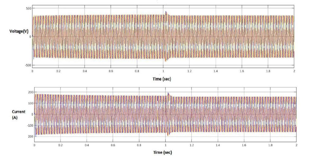
Fig. 4 indicates source voltage waveform wherein voltage sag is observed in among zero- 1 second. The voltage and current waveforms of department in which nonlinear loads are substantial with inclusion of DVR are shown in Fig. 5.
Also, Fig. 6 and 7 indicates voltage THD values earlier than and after DVR connection for a linear and nonlinear load.


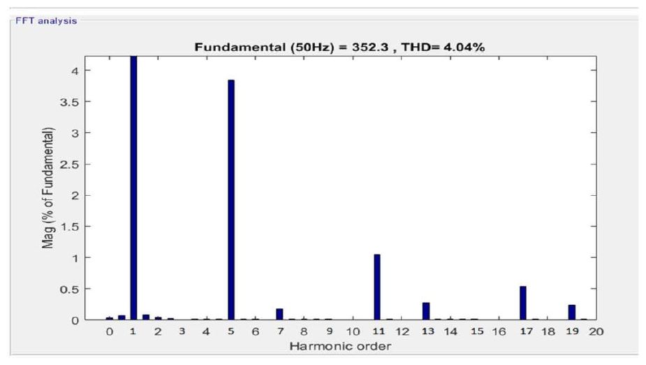
THD readings are determined for nonlinear load. Also current THD readings are observed for linear and nonlinear loads before and after DVR implementation inside the system and effects are represented in Table 2.
TABLE II
SYSTEM RESULTS

Table 2 indicates the decreased values of THD because of inclusion of DVR in the system. Same results can be observed after connecting DVR in other departments of device with distinct loads.
B. Distortion Index Calculations
Along with THD analysis some other parameter known as Distortion Index (DI) is calculated for the system and is analyzed via simulation. Following formulae are used to calculate DI.
Following formulae are taken into consideration to calculate Distortion Index. Let us consider V1 and I1 be the fundamental voltage and current. V3, V5, V7,…..Vn and I3, I5, I7,……… In are orders of harmonic voltages and currents respectively.
IH = √I32 + I52 + I72 (1)
VH = √V32 + V52 + V72 (2)
Total Harmonic Distortion Voltage VTHD = VH / V1 (3)
Total Harmonic Distortion Current ITHD = IH / I1 (4)
Fundamental Apparent Power FAP = V1I1 (5)
Current Distortion Power CDP = V1IH (6)
Voltage Distortion Power VDP = VHI1 (7)
Harmonic Distortion Power HDP = VHIH (8)
Non-linear Apparent power NAP = √CDP2 + VDP2 + HDP2 (9)
Total Apparent Power TAP = √FAP2 + NAP2 (10)
Distortion Index DI = NAP / FAP *100 (11)
Table 3 indicates DI values for departments D1-D9 in the system before DVR connection and after DVR connection.
TABLE III
DISTORTION INDEX


IV. CONCLUSIONS
From various observations, the outcomes are in comparison. It has been highlighted that the harmonic contents and Distortion Index is reduced significantly with the inclusion of DVR in system. In this regard, a new procedure is presented which evaluates the Distortion Index with DVR and without DVR for non-linear loads connected to the power distribution network.
Contribution of Power Quality Indices is the most important subject to reveal Power Quality stages often. From observations Total Harmonic Distortion displays most effective voltage or the current distortion, while, Distortion Index(DI) pertains to distortion in distribution power. Hence DI can be introduced as main Power Quality index for identification and evaluation of Power Quality levels present inside the distribution network. The regulatory authority can consider this index as “Quality factor” or “Penalty Factor”
ACKNOWLEDGMENT
The research work is being carried out in Bharti Vidyapeeth Deemed University COE, Pune in consent with MSEDCL, Pune. The authors desire to thank authorities of BVDUCOE, Pune for granting permission to publish the work.
REFERENCES
[1] T. Sarwade, V. S. Jape, and D. G. Bharadwaj, “Power quality problems mitigation using dynamic voltage restorer (DVR) using pi controller and fuzzy logic controller,” IJET, vol.2 issue 12, pp. 214-218, Apr. 2018.
[2] C. H. Raval, and A. Doorwar, “An Overview of Various Control Methods of DVR,” in ICCPCT, 2014, p. 53
[3] R. Omar, and N. A. Rahim, “Implementation and Control of a Dynamic Voltage Restorer using Space Vector Pulse Width Modulation (SVPWM) for Voltage sag Mitigation,” in IEEE-TECHPOS, 2009, p. 1.
[4] V. S. Jape, and D. G. Bharadwaj, “Substation Monitoring System (SMS) For Remote Power Quality Monitoring and analysis of Power Distribution Network using Object Oriented Web Enabled Method,” IJCTA(International Science Press), 10(9), pp. 533- 539, 2017.
[5] R. C. Dugan, and M. F. McGranghan, Electrical Power System Quality, Tata McGraw Hill, 2nd Edition.
[6] S. Vlahinic, D. Brnobic, and N. Stojkovic, “Indices for harmonic Distortion Monitoring of Power Distribution Systems,” Instrumentation, pp. 12-15, 2008.
[7] IEEE Recommended Practices and Requirements for Harmonic Control in electrical Power Systems, IEEE Std 519-1992.
[8] IEEE Recommended practice for monitoring electric power quality, IEEE STD 1159-1995.
Source: JASC: Journal of Applied Science and Computations, ISSN NO: 1076-5131, Volume 5, Issue 10, October/2018
