Published by Electrotek Concepts, Inc., PQSoft Case Study: Ferroresonance Analysis – 25kV Single 5-Legged Core Transformer, Document ID: PQS0318, Date: July 18, 2002.
Abstract: Ferroresonance is a concern for medium voltage underground systems. As part of an evaluation of the design of a new 25kV underground system, the potential for ferroresonance was analyzed. Ferroresonance requires a certain length of cable to generate severe overvoltages. With modern transformers, this length is frequently less than 200 ft. Our calculations suggest that the threshold of ferroresonance is about 100 ft for a modern 2500 kVA transformer and 1000 kcmil cable and it is certainly in ferroresonance at 200 ft. These distances are proportionately shorter for smaller transformers. This makes it more difficult to achieve ferroresonance-free installations where single-phase switching or fusing is permitted because the maximum cable length is impractically short. As a general guideline, three-phase switching should be strongly considered for cable length exceeding 100 ft. If the switchgear can be mounted closer to the transformer, fused switching may be used with little fear of serious overvoltages.
PROBLEM STATEMENT
An electric utility was evaluating the proposed design of a new, predominantly underground, 25kV system. One of the concerns of the utility related to the new system was the likelihood of 25kV transformers experiencing ferroresonant conditions. This case study was an effort to characterize the combinations of parameters that would increase the probability of ferroresonance.
SYSTEM MODEL
The complete three-phase schematic of the circuit used to evaluate ferroresonance on a single 5-legged core transformer is shown in Figure 1.
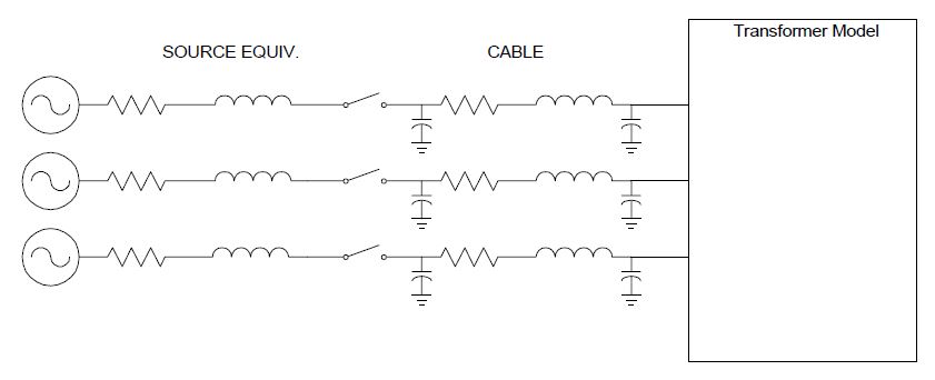
This model was represented in the EMTP program and executed for a number of cases. The variables were:
- The length of the cable. Lengths from 100 ft up to 2000 ft were considered.
- Transformer size. The transformer model was scaled from 2500 kVA down to 150 kVA.
- The number of phases open: either one or two.
The simulation was started with all three switches open and then either one or two phases were closed within a few milliseconds. This creates a transient flux condition in the transformer that is intended to send it into a high ferroresonance mode if one exists.
The transformer was assumed to be a 5-legged core design. The five-legged core transformer is of particular interest because it is likely to be the most common 3-phase transformer applied to the 25kV system. It is also the most difficult to model. The 5-legged core transformer model utilized for the evaluation is a model based on Transient Network Analyzer (TNA) technology that basically assumes that the 5-legged core transformer looks the same from each phase and essentially behaves like a symmetrical 4-legged core. This model is shown in Figure 2 and well represents imbalances associated with the center leg of the transformer. The results presented in this case study are those from simulations using this simplified model.
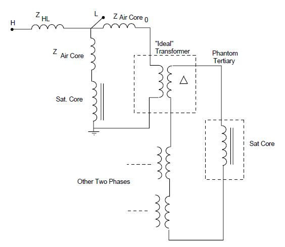
obtained by inserting a saturable element in the corner of the delta in the “phantom tertiary”.
ANALYSIS
Figure 3 shows a plot of the computed voltages appearing on the cable versus cable length for a variety of transformer sizes. The peak of the transient voltage that appears upon energization of the second phase in phase-by-phase switching is plotted. The inrush transient generates a fair amount of high frequency “hash” as is evident in the representative waveforms in Figure 6 and Figure 7. This high frequency transient results from a combination of the transformer being driven heavily into saturation upon inrush and the low assumed losses in the transformer model. It disappears quickly in the presence of a few additional losses. In practice, it may die out in few seconds (although it would be interesting to conduct live tests for comparison to see if actual transformers really do demonstrate the low losses).
For the purposes of comparison, this transient peak is much higher than the steady state values reported in the literature where the typical peak voltage is 2 to 2.5 per unit and is quite sensitive to the loss model. However, we have chosen to plot this voltage because the resulting curves clearly point to the lengths of cable at which ferroresonance begins to be a problem.
Industry analysts have historically assumed that when this voltage exceeds 125%, the system is said to be “in ferroresonance”. Of course, there is similar activity even when lower voltages appear. At 100 ft of cable, all the transformer sizes meet this criterion when there is no load. The 2500 kVA transformer just meets this criterion at 100 ft and is definitely in ferroresonance by 200 ft. The smaller transformers require proportionately less cable. The 150 kVA transformer is somewhat of an anomaly, indicating the fickleness of ferroresonance.
upon energization of the second phase, for various transformer sizes; no load.
Figure 4 shows the effect of resistor load on ferroresonance. We took two lengths of cable, 500 ft and 2000 ft, for which the 2500-kVA transformer exhibited significant ferroresonance at no load and plotted the peak voltage appearing on the cable for a range of balanced resistive loads on the transformer. As can be seen, the overvoltage drops quickly with the addition of only 1 or 2% load. Technically, the transformer is still “in ferroresonance” up to about 5% load and the voltage magnitudes are near normal, or less than normal, at 15% load. This is in almost complete agreement with what has been reported in the literature.
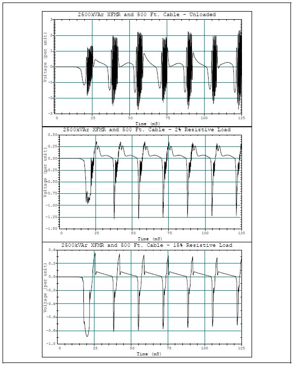
Figure 5 shows a set of three waveforms of the voltage for successively increasing load. The rapid drop in ferroresonant voltage magnitude with the introduction of load is due in large part to the damping of the high frequency portion of the transient. This disappears quickly. The remaining voltage waveform bears a strong resemblance to many of the steady state waveforms reported in the literature.
Figure 6 and Figure 7 show other representative waveforms illustrating the variation of waveforms with transformer size and cable length, respectively.
CONCLUSIONS
From these results and the review of the literature concerning trends in ferroresonance with modern transformer designs, we have concluded that it is likely that ferroresonant activity resulting in voltages exceeding 1.25 per unit will occur during normal phase-by-phase switching events and abnormal failure-related events. Based on what we know about how the system will be designed at this time, it appears that the transformers can become isolated on sufficiently long pieces of cable to cause ferroresonance. The threshold of ferroresonance occurs at approximately 100 ft. of cable.
Grounded wye-wye, 5-legged core transformers are not likely to get into a ferroresonance mode that will result in immediate failure of the transformer or connected cables. In fact, for many cases the voltage will not be high enough to cause utility arresters to operate (although customer arresters may). Therefore, if ferroresonance occurs during a switching operation, no damage would be expected if the operation is completed promptly. The greater danger is with ferroresonance that persists undetected for several minutes or hours. Customer equipment may suffer damage even on brief occurrences.
Although we did not simulate it extensively, many sources indicate that delta-connected transformers can easily achieve voltages exceeding 2.5 per unit. They tend to stay in the higher ferroresonance modes we observed in our simulations of the 5-legged core transformer. This can result is rather rapid failure of equipment and protection should be applied
RECOMMENDATIONS
− Fuse protection should be avoided when the length of cable between the fuse and a ferroresonance-susceptible transformer exceeds about 100 ft. Use three-phase tripping fault interrupters instead. This is similar to the recommendations of other investigators who would suggest critical lengths in the range of 60 to 200 ft for a 2500 kVA transformer.
− Phase-by-phase switching of unloaded transformer when more than 100 ft of cable is involved should be done with the anticipation of ferroresonance.
− Operating procedures should be reviewed in light of the possibility of ferroresonance and revised where necessary.
− Customers with critical loads who may have a desire to dump the utility bus and switch to backup power at the first sign of utility system trouble, should be advised to design their systems to leave significant lighting loads on the utility bus to reduce the chances that the ferroresonance will be damaging.
− Delta-connected transformers should be avoided on the 25-kV system. If present, they should be protected with adequate arresters. If such a transformer is discovered in ferroresonance, it should be de-energized completely for a sufficient time to allow the arresters to cool before re-energization.
REFERENCES
- Reinhold Rudenberg, Transient Performance of Electric Power System, MIT Press, May 1970, Chapter 48.
- B.A. Mork, D. L. Stuehm, “Application of Nonlinear Dynamics and Chaos to Ferroresonance in Distribution Systems,” IEEE/PES Summer Meeting, Vancouver, 1993, Paper No. 93 SM 415-0 PWRD.
- Xusheng Chen, “A Three-phase Multi-legged Transformer Model in ATP using the Directly-formed Inverse Inductance Matrix,” Paper No. 95 SM 421-8 PWRD, IEEE/PES Summer Meeting, Portland, OR, 1995.
- D. L. Stuehm, B. A. Mork, D. D. Mairs, “Five-legged Core Transformer Equivalent Circuit,” IEEE Transactions on Power Delivery, Vol 4, No. 3, July 1989.
- R. A. Walling, et. al., “Performance of Metal-Oxide Arresters Exposed to Ferroresonance in Padmount Transformers,” IEEE Transactions on Power Delivery, Vol 9., No. 2, April 1994, pp. 788 ff.
RELATED STANDARDS
IEEE C57.105-1978
GLOSSARY AND ACRONYMS
TNA: Transient Network Analyzer
