Published by Electrotek Concepts, Inc., PQSoft Case Study: Distribution Feeder Energizing, Document ID: PQS0711, Date: October 15, 2007.
Abstract: The energization transients for distribution feeders are generally a combination of line energizing, transformer inrush, and load inrush. Line energizing transients typically decay to negligible values in about one-half cycle and they generally do not pose significant problems for customer equipment. Energizing a distribution circuit can create a transient overvoltage similar to that generated by a capacitor bank energizing.
This case study presents a feeder energizing evaluation for a 34.5kV distribution system.
INTRODUCTION
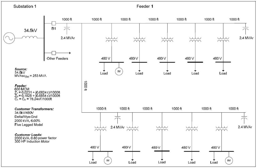
A feeder energizing evaluation was completed for the 34.5kV distribution system shown in Figure 1.
BACKGROUND
The energization transients for distribution feeders are generally a combination of line energizing, transformer inrush, and load inrush. Line energizing transients typically decay to negligible values in about ½ cycle and they generally do not pose significant problems for customer equipment.
Energizing a distribution circuit (e.g., lines and/or cables) can create a transient overvoltage similar to that generated by a capacitor bank energizing. Transients generated by energizing overhead distribution lines are characterized by high frequencies (e.g., 2-10 kHz) because of the small effective shunt capacitance (e.g., 15 ηF/mile) of these circuits. These high frequencies are quickly attenuated by the distribution line resistance and circuit loads. Long cable circuits have higher capacitance (500-1000 ηF/mile) and can look similar to capacitor banks when they are energized. This means that the characteristic frequencies are lower (e.g., 500-2000 Hz) and the transients can last longer. If the distribution circuits include capacitor banks, the energizing transients will be dominated by the capacitor banks and the associated frequencies will be lower (e.g., 300-800 Hz).
Besides, the effect of the line or cable capacitance, energizing transmission lines also causes traveling waves that appear as high frequency transients. Traveling waves are caused by the distributed nature of the capacitance and inductance of the transmission or distribution line. These transients are damped by circuit resistance and load on the power system but can be a concern during light load conditions. The frequencies are high enough (natural frequencies of distribution circuits without shunt capacitors are in the range 1-10 kHz) that these transients can be coupled to secondary circuits by the capacitance ratio of step-down transformers.
Figure 2 shows an example measured voltage waveform on a 12.5kV feeder during reclosing after clearing a fault on the feeder.
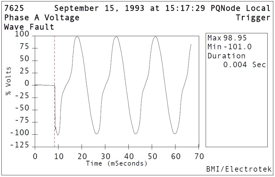
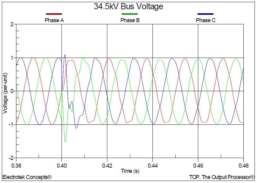
Figure 3 shows an example measured three-phase voltage waveform on a 13.8kV substation bus during energization of a distribution feeder. The worst-case transient voltage was approximately 1.71 per-unit (171%).

SIMULATION RESULTS
The accuracy of the system model was verified using three-phase and single-line-to-ground fault currents and other steady-state quantities, such as transformer and induction motor rated currents. The distribution circuit model has two branches, each approximately 6000-7000 feet in length. Customer loads are distributed along the entire length of the feeder, with three of customer transformers also supplying 300 hp induction motors. Several 2,400 kVAr capacitor banks are placed along the feeder to maintain a reasonably constant steady-state voltage profile. The customer transformers are modeled using a five-legged core design.
The lengths of the cable segments were 1,000 feet. The cable size was 600 MCM with the following characteristics:
Insulation:……………………………….0.1406 outside diameter in feet
Jacket:……………………………………0.1412 outside diameter in feet
Neutral:…………………………………..0.1409 outside diameter in feet
A line constant program was used to compute the positive and zero-sequence impedances of the cable, yielding the following results:
Z1 = 0.0231 + j 0.0824 ohms/1000 ft
Z0 = 0.1828 + j 0.6854 ohms/1000 ft
C1 = C0 = 78.24 ηF/1000 ft
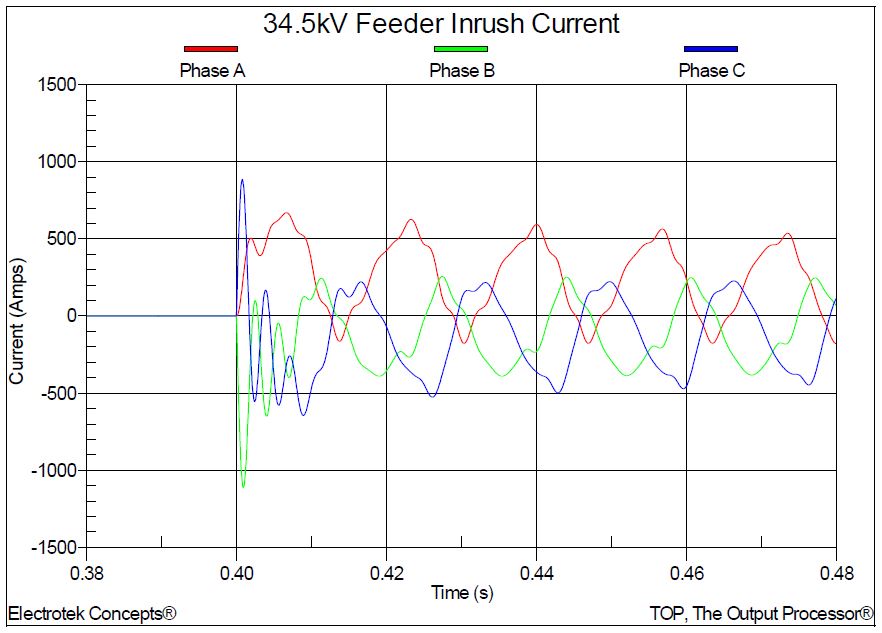
The initial case (Case 3a) involved energizing the 34.5kV distribution feeder by closing the circuit breaker B1 with all of the customer load and capacitor banks in-service. Figure 4 shows the three-phase bus voltage at the 34.5kV substation bus when the circuit breaker B1 is closed. Figure 5 shows the corresponding 34.5kV feeder inrush current.
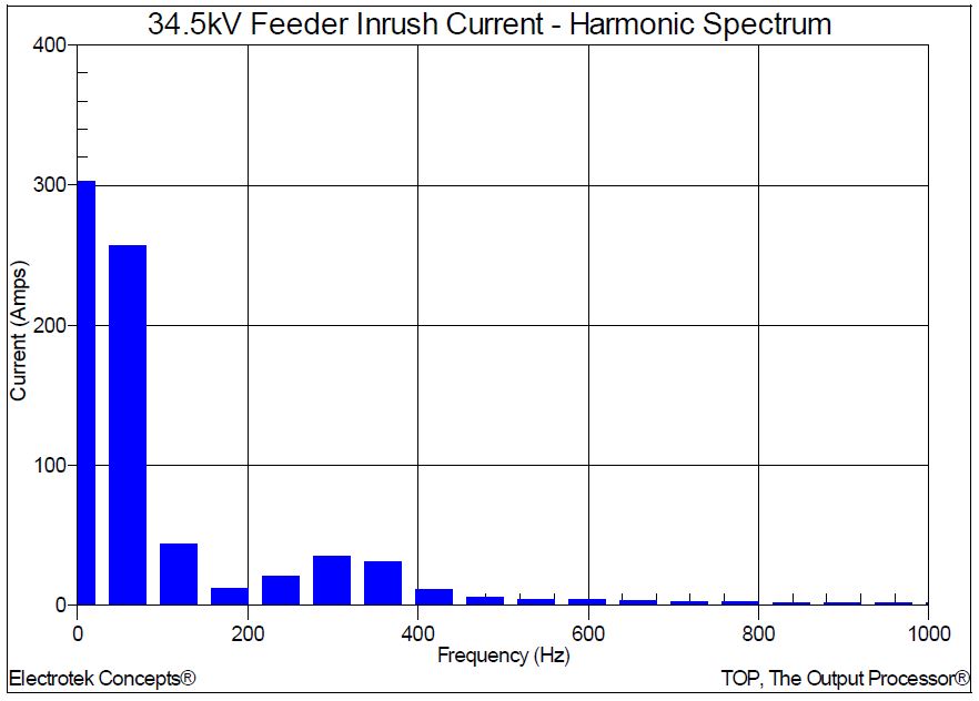
Figure 6 shows the results of a Fourier analysis of the current waveform. The highest harmonic current components are between the 2nd and 7th harmonics, which correspond to the characteristic frequencies for load, transformer, and capacitor bank energizing transients.
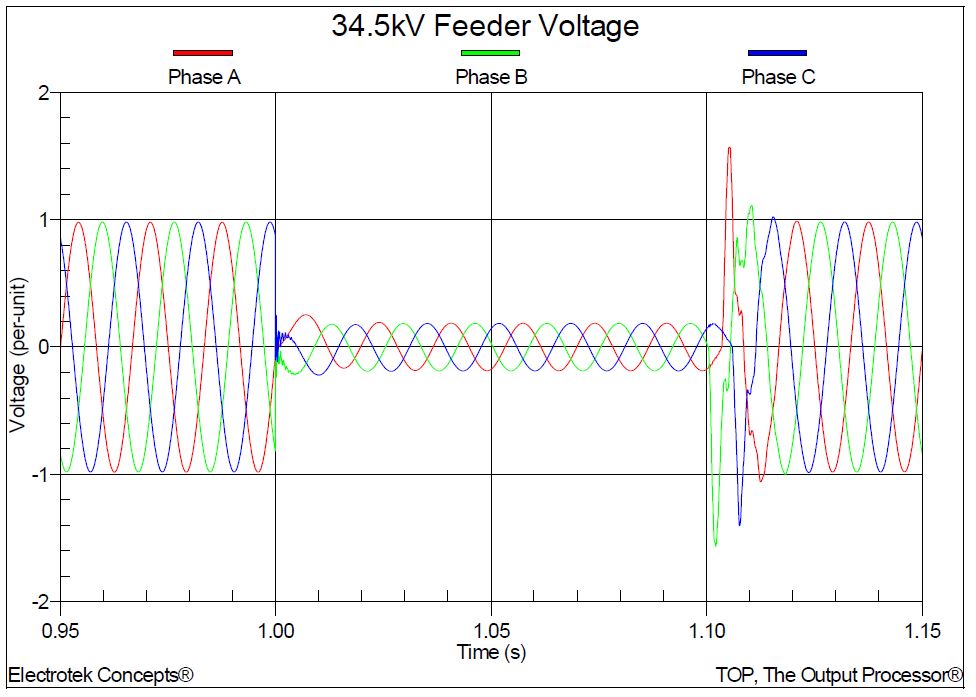
The second case (Case 3b) shows the effect of a short duration fault and circuit breaker reclosing on the feeder voltage waveform. Figure 7 shows the three-phase voltage near the end of one branch of the 34.5kV distribution feeder during a six-cycle fault at the end of the feeder.
CONCLUSIONS
Observations and conclusions for this case study include:
- Distribution feeders energizing transients are generally a combination of line energizing, transformer inrush, and load inrush transient characteristics.
- Long distribution cable circuits have relatively high capacitance (500-1000 ηF/mile) and can look similar to capacitor banks when they are energized. This means that the characteristic frequencies are relatively low (e.g., 500-2000 Hz) and the transients can last significantly longer.
- For distribution circuits that include capacitor banks, the energizing transients will be dominated by the capacitor banks and the associated frequencies will be approximately 300-800 Hz.
- Distribution feeder energizing transients typically decay to negligible values in about ½ cycle and they generally do not pose significant problems for customer equipment. Excessive transient overvoltages will likely be limited by arresters installed on substation and feeder equipment.
RELATED STANDARDS
IEEE Std. 1036
GLOSSARY AND ACRONYMS
MOV: Metal Oxide Varistor Arrester
MSSPL: Maximum Switching Surge Protective Level
SiC: Silicon Carbide Arrester
