Published by Electrotek Concepts, Inc., PQSoft Case Study: Voltage Sag Study – Application of a Static Transfer Switch, Document ID: PQS0317, Date: July 18, 2003.
Abstract: The purpose of this case study is to determine the feasibility of reducing process equipment disruptions due to utility voltage sags at a large industrial facility. The facility consists of many injection molding machines, resulting in an industrial process that is extremely sensitive to distribution voltage variations. The case study investigates various distribution system modifications to determine the most effective and efficient means for providing the level of power quality necessary for proper plant operation.
INTRODUCTION
The purpose of this study is to determine the feasibility of reducing process equipment disruptions due to utility voltage sags at a large industrial facility. The study focuses on necessary modifications to the utility distribution system.
The plant manufactures plastic cases for automobile batteries and is served by 480-V, three-phase, four-wire. The plastics plant operates 24/7, peaks at about 1000 kW, and has an annual electricity cost of approximately $347,000. The customer has not reported the magnitude of dollar losses associated with voltage sags, nor have they provided log information about the number of disturbances suffered and the specific equipment affected. In addition, the customer has insisted that the voltage sag problem be solved on the utility system, rather than inside the plant. The manufacturer says they are not unwilling to modify the existing injection molding machines to provide selective ride-through, nor does it want to bear the expense of providing ride-through equipment capable of protecting entire machines.
Customer Equipment and Utility Supply Description
Injection Molding Machines
The plant operates 19 injection molding machines and two automatic assemblers. Each machine consists of an ac hydraulic pump motor, a dc extruder motor, and electronic controls and robotics. The total connected molding machine load is about 2000 kW. Plant billing demand is about 1000 kW, but is soon to increase with the addition of ten machines. The plant is highly automated and requires only 7 operating personnel. The few operators make for difficult recovery when production upsets occur. The typical voltage sag disrupts the computer controls serving robotics and causes drop-out of magnetic contactors for the hydraulic pumps.
Summary
The plant is served from Delivery #3 (Del#3), a transmission-to-distribution substation. The substation is fed from the local utility’s 100 kV transmission system. The plant’s 23 kV feeder is designated as Circuit 332 and is shown schematically in Figure 1. Del#3 also serves three other 23 kV distribution feeders, 333, 334, and 335. The local utility operates two similar points-of-delivery, designated as Delivery #1 (Del#1) and Delivery #2 (Del#2). Circuit #112, from Del#1, is being considered as the source of an alternate 23 kV feed to the plant because it will be extended to the vicinity of the customer’s site to accommodate system improvement and load growth requirements.
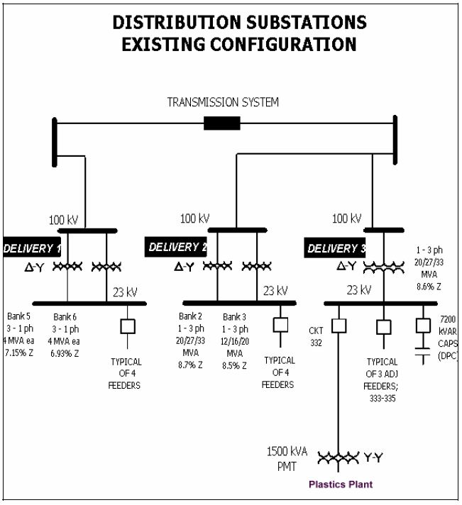
The city should expect one to two feeder breaker operations per month per feeder on its 23 kV distribution system. Based on Electrotek’s experience, this level of activity is typical for overhead distribution systems with multiple feeders per substation with the kind of animal, vegetation and lightning exposure which exists in the area. Standard construction, multiple feeder per substation, overhead distribution circuits are not designed to provide the type of performance required by sensitive industrial customers like the one here.
Utility-Side Solution to Voltage Sag Disturbances
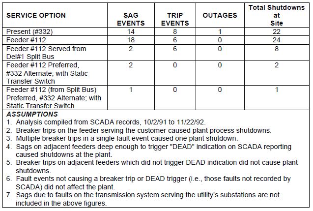
Table 1 summarizes the utility-side options for reducing voltage sag interruptions at the plant. The table is arranged with the present service (Feeder #332 out of Del#3) listed first, and the other service options listed in order of decreasing interruptions at the customer’s site. This table is based upon the utility’s SCADA information and utilizes several assumptions (outlined in Table 1). The most important of these assumptions is that the table is based on one test year of interruption data. Fault data in other years may be considerably different. The table also does not include sags due to faults on the transmission system.
Table 1 Utility-Side Options for Improving Service at the Customer’s Site
Recommended Solution — Dual Feed and Static Transfer Switch
Electrotek recommends that the utility install a dual-feed service to the plant which includes an electronic static transfer switch, as shown schematically in Figure 2. This service will dramatically reduce the number of interruptions to the plant, and can be integrated into the utility’s load growth plans to relieve some of the installed cost of the system. Preliminary estimates indicate that the new service can be installed for about $300,000, not including the costs to extend Circuit #112 to the site.
Table 2 shows a breakdown of the estimated costs.
Table 2 Breakdown of Costs to Install Static Transfer Switch and Monitor Performance
Operating costs for the static transfer switch are expected to be minimal. The manufacturer lists the switch efficiency at 99.5%. Power losses in the switch therefore will add less than $5000 to the customer’s annual billing. Similar static transfer switch installations have not been air conditioned, so the additional energy costs related to the switch will be limited to ventilation fan operation. The electronic components require little maintenance.
Static Transfer Switch
The electronic static transfer switch consists of silicon-controlled rectifiers (SCR’s) which can quickly disconnect sensitive loads from a preferred source, and re-connect the loads to an un-faulted alternate source. At the plant, the preferred source would be the new 2500 kVA padmount transformer served from Circuit #112, while the alternate source would be the existing service. The static transfer switch can transfer to the alternate source in approximately ¼ to ½ cycles.
The static transfer switch will transfer to the alternate source under the following conditions:
- Source undervoltage (less than about 80% on any single phase);
- Source overvoltage (greater than 110%);
- Loss of continuity in source-side SCR (SCR failure);
- Blown fuse in source;
- Manual signal.
It is designed to transfer back to the preferred source when:
- The preferred source is in-phase;
- The preferred source is within 10% of nominal voltage for greater than 2 sec (adjustable);
- Operator switch is in “automatic” position;
- The transfer to alternate was not caused by an SCR failure.
Electrotek expects that the switch will alleviate the majority of voltage sags which cause an adverse impact to plastics plant. The plant will still be susceptible to deep sags on the utility’s transmission system, distribution system faults which affect Del#1 and Del#3 simultaneously, and failures in the static transfer switch itself. These occasions are expected to be rare.
SUMMARY
Electrotek recommends that the utility combine planned system improvements with modifications in its service to the plastics plant to lessen the plant’s exposure to voltage sags. The proposed project would include splitting the Del#1 23 kV bus, extending Circuit #112 to the customer’s site, installing a new 2500 kVA transformer to accommodate additional load growth within the customer’s facility, and installing an electronic static transfer switch capable of transferring the plant load to Circuit #332 during interruptions and voltage sags on Circuit #112. Electrotek estimates that the static transfer switch will add approximately $300,000 to the system improvement project.
Modifications to a utility system which benefit a single customer are generally paid for by that customer. Normal utility practice is to apply additional facilities charges to the customer’s monthly electric bill to cover the cost of the improvements. These monthly charges generally equal 1.0% to 2.0% of the installed cost of the improvements and apply indefinitely. The utility uses a plan which applies a monthly charge of 1.7%. The additional facilities charge under this plan would add less than 10% to the customer’s projected monthly billing after the expansion.
The plastics manufacturer could realize a significant reduction in economic losses associated with voltage sags by accepting the static transfer switch solution. These savings could be applied against the additional facilities charges. In addition, the customer’s load growth may qualify the plant to receive an economic development incentive rate. The incentive rate savings, by utility calculations, could exceed $150,000 over the next five years. These savings would also lessen the impact of the facilities charges.
REFERENCES
Static Transfer Switch Primer, EPRI, Palo Alto, CA, 1998, TR-111697.
Banerjee, B., Smith, J., The Static Transfer Switch: Current Technologies, Operation, and System Requirements, PQA ’99, Charlotte, North Carolina, May 1999.
GLOSSARY AND ACRONYMS
Voltage Sag: A decrease to between 0.1 and 0.9 pu in rms voltage or current at the power frequency for durations from 0.5 cycles to 1 minute.
