Published by Mirus International Inc., [2010-01-08] MIRUS-FAQ001-B2, FAQ’s Harmonic Mitigating Transformers, 31 Sun Pac Blvd., Brampton, Ontario, Canada. L6S 5P6.

It is much more difficult to accurately determine the energy efficiency of a transformer under non-linear loading than it is under linear loading. The industry accepted technique for measuring transformer efficiency under linear load involves measuring losses using Open Circuit and Short Circuit Tests. The Open Circuit or No-load Test measures core losses (iron losses). The Short Circuit Test or Load Test measures load losses which are also called I2R losses or copper losses. This allows for calculation of Transformer Efficiency = Output Power / (Output Power + Total Losses). This calculation is equivalent to Efficiency = Output Power / Input Power but produces more accurate and repeatable results.
The example below shows how very accurate efficiency calculations can be achieved by measuring losses directly even with a relatively inaccurate power meter (+/- 1.0%).
True Output Power = 97 kW
True Input Power = 100 kW, Losses = 3 kW
True Efficiency = 97 / 100 or 97%.
Measuring losses directly with a +/- 1.0% power meter yields a measurement error of only +/- 0.03% as follows:
Output Power = 97kW
Measured Losses = 3kW – (0.01 x 3 kW) = 2.97 kW
Efficiency = 97/ (97 + 2.97) = 97 / 99.97 = 97.03%
Unfortunately this method of directly measuring the losses themselves inherently applies only to transformer operation with a linear load. For non-linear load we must revert to a much less accurate method of calculating efficiency based upon direct measurements of Output and Input Power. This method will only produce acceptable results if measurements are taken simultaneously by two highly accurate power meters.
An example of how output power vs input power measurements using meters of average measurement accuracy (ie. +/- 0.5%) can produce misleading results is shown below. The earlier example is used but this time measuring input and output power with a meter of +/- 0.5% accuracy (better than previous +/- 1.0%).
Measured Output Power = 97kW + 0.5kW = 97.5 kW
Measured Input Power = 100kW – 0.5kW = 99.5kW
Calculated Efficiency = 97.5 / 99.5 = 98%, a full 1% error despite measurement accuracy within +/- 0.5%.
This results in a reported 98% efficiency for a transformer that is truly only 97%. Similarly, the calculated result could have been 96% if the errors were reversed. To emphasis the significance of this error, reporting 98% on a transformer that is actually 97% means losses are under reported by a full 1/3 (ie. 2% losses instead of 3%). The measurements are essentially useless. This inaccuracy is magnified further if only one meter is used because even a very small change in the load power between measurements will very dramatically affect the results.
To provide truly accurate and reliable transformer efficiency measurements under non-linear loading, Mirus has built a Non-linear Load Test facility, known as the Harmonics & Energy or H&E Lab, at its manufacturing facility near Toronto (see Figure 16-1).

The H&E Non-linear Load Bank has the capability of loading transformers up to 225 kVA to their full load rating. Larger transformers can be loaded proportionately (ie. 500 kVA to 45% load). This is believed to be the largest 120V phase-to-neutral non-linear load bank of any transformer manufacturer, including all other HMT manufacturers.
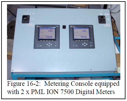
In order to achieve the most accurate measurements possible, the H&E Lab is equipped with two revenue class digital power meters with an accuracy of 0.1% and current transformers with 0.3% accuracy. The meters can measure up to the 63rd harmonic. One meter is used to connect to the transformer primary while the second meter is connected to the transformer secondary. To further improve measurement accuracy, efficiency calculations are based on kW-sec totalization rather than on instantaneous kW readings in order to minimize any sample timing error.
The Non-linear Load Bank in the H&E Lab consists of several Variable Frequency Drives fed with 1-phase power. When supplied with 1-phase power, the 3-phase diode bridge rectifier of a VFD draws current which has a waveform and harmonic spectrum that is representative of a very high K-factor, 1-phase non-linear load similar to that of computer power supplies and other power electronic equipment connected phase-to-neutral.
A sample of the typical load profile of the Non-linear Load Bank is shown in Figure 16-3. In this example, a 45 kVA transformer was operated at both 100% and 50% loading. At full load, secondary current was 129A with a K-factor of just over 9 and current total harmonic distortion (Ithd) of 81%. At 50% load, the K-factor increased to over 13 with Ithd > 90%.
In summary, claims of highly accurate transformer testing under non-linear loading by any party should not be accepted without reviewing their complete test procedure and full test report including documentation on measurement techniques and certified instrumentation accuracy. This is particularly important if testing was performed with a single power meter because it would be impossible to take measurements simultaneously..
Harmonics and Harmonic Mitigating Transformers (HMT’s) Questions and Answers
This document has been written to provide answers to the more frequently asked questions we have received regarding harmonics and the Harmonic Mitigating Transformer technology used to address them. This information will be of interest to both those experienced in harmonic mitigation techniques and those new to the problem of harmonics. For additional information visit our Website at www.mirusinternational.com.
