Published by L&T Electrical & Automation, Website: lntebg.in
Source: https://www.lntebg.in/about-us/blog/understanding-current-voltage-harmonics/
Current and voltage harmonics are often used interchangeably. At most places, only harmonics is quoted and whether the values pertain to current or voltage is not mentioned. The differentiation can be done on the basis of their origin.
Understanding Total Harmonic Distortion
The current and voltage harmonics in a system are often expressed as Total Harmonic Distortion (THD). The total harmonic distortion or THD, of a quantity is a measurement of the harmonic distortion present and is the ratio of all harmonic components to the fundamental component. It is give by the formula as under:
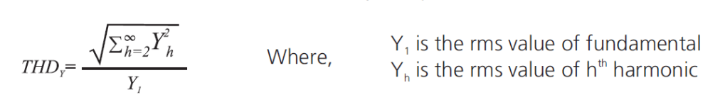
Hence, current THD is the ratio of the root-mean-square value of the harmonic currents to the fundamental current.

Where do Current & Voltage Harmonics Originate?
Harmonics always originate as current harmonics and voltage harmonics are the results of current harmonics. Current harmonics originate because of the presence of non-linear loads like variable speed drives, inverters, UPS, television sets, PCs, semiconductor circuits, welding sets, arc furnaces in the system. They act as harmonic current sources. The resulting current waveform can be quite complex depending on the type of load and its interaction with other components of the system.

The distorted current waveforms can be represented as the sum of current waveform of fundamental frequency and of its multiple (harmonics):

Voltage harmonics do not originate directly from non-linear loads. The current harmonics (distorted waveform) flow through system impedance (source and line impedances) and cause harmonic voltage drop across the impedances. This will distort the supply voltage waveform. Thus voltage harmonic are generated. Long cable runs, high impedance transformers, etc. contribute to higher source impedance and hence, higher voltage harmonics.
A typical power system has the following impedances as indicated in the line diagram:
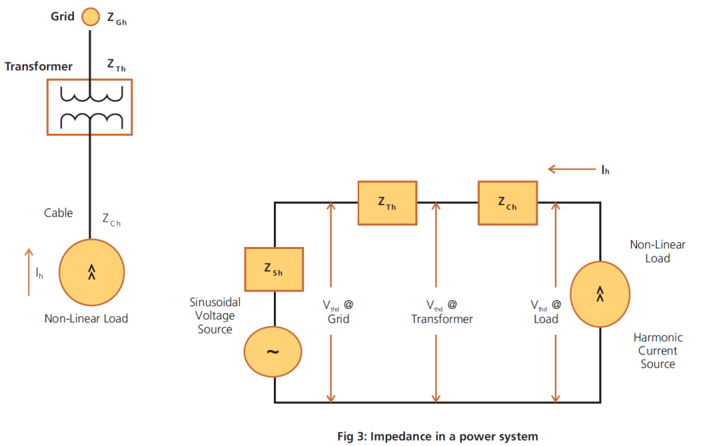
In the above diagram,
- Vh = hth harmonic voltage
- Ih = hth harmonic current
- Zh = Impedance at hth harmonic
- Vthd = Voltage total harmonic distortion
- At load, Vh = Ih x (ZCh + ZTh + ZGh)
- At transformer, Vh = Ih x (ZTh + ZGh)
- At grid, Vh = Ih x (Zgh)
Usually, grid impedances are very low and hence, the harmonic voltage distortion are also low there. However, they may be unacceptably higher on the load side as they are subjected to full system impedance there. Hence, it becomes important where the harmonics measurements are done.
However, in case of DG sets, the source impedance is large resulting in high voltage harmonics despite small current harmonics. Thus, a clear distinction between current and voltage harmonics becomes important here.
An industry, say industry A, that has large non-linear loads will generate huge current harmonics in its system. A nearby industry, say industry B, connected to the same grid may not have non-linear loads, yet, it may be subjected to high voltage harmonics. These voltage harmonics are the result of high current harmonics of industry A and impedance of grid & transformer. Thus, industry B despite small current harmonics, has high voltage harmonics may also appear in the systems, magnifying voltage harmonics further.
How do Current & Voltage Harmonics Affect the System?
Current harmonics increase the rms current flowing in the circuit and thereby, increase the power losses. Current harmonics affect the entire distribution all the way down to the loads. They may cause increased eddy current and hysteresis losses in motor and transformers resulting in over-heating, overloading in the neutral conductors, nuisance tripping of circuit breakers, over-stressing of power factor correction capacitors, interference with communication etc. They can even lead to over-heating and saturation of reactors.
Voltage harmonics affect the entire system irrespective of the type of load. They affect sensitive equipment throughout the facility like those that work on zero-voltage crossing as they introduce voltage distortions.
Understanding IEEE 519 Guidelines
The purpose of harmonic limits in a system is to limit the harmonic injection from individual customers to the grid so that they do not cause unacceptable voltage distortion in the grid. IEEE 519 specifies the harmonic limits on Total Demand Distortion (TDD) and not Total Harmonic Distortion (THD). TDD represents the amount of harmonics with respect to the maximum load current over a considerable period of time (not the maximum demand current), whereas, THD represents the harmonic content with respect to the actual load current at the time of measurement.
It is important to note here that a small load current may have a high THD value but may not be significant threat to the system as the magnitude of harmonics is quite low. This is quite common during light load conditions.
TDD limits are based on the ratio of system’s short circuit current to load current (ISC/IL). This is used to differentiate a system and its impact on voltage distortion of the entire power system. The short circuit capacity is a measure of the impedance of the system. Higher the system impedance, lower will be the short circuit capacity and vice versa.
The Guidelines IEEE 519-2014 at PCC Level are as under:
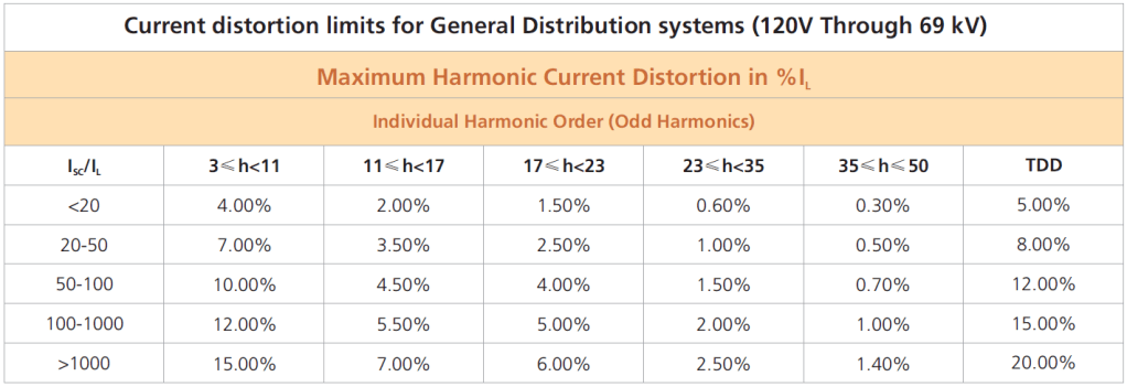
where
- ISC = maximum short-circuit current at PCC [Can be calculated as MVA/(%Z x V)]
- IL = maximum demand load current (fundamental frequency component) at PCC
Systems with higher ISC/IL have smaller impedances and thus they contribute less in the overall voltage distortion of the power system to which they are connected. Thus, the TDD limits become less stringent for systems with higher ISC/IL values. In other words, higher the rating of transformer used for the same amount of load, higher will be the allowable current distortion limits.
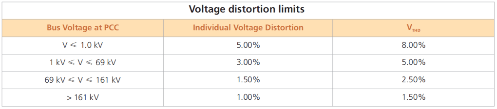
The limits on voltage are set at 5% for total harmonic distortion and 3% of fundamental for any single harmonic at PCC level. Harmonics levels above this may lead to erratic functioning of equipment. In critical applications like hospitals and airports, the limits are more stringent (less than 3% VTHD) as erroneous operation may have severe consequences. As discussed already, the harmonic voltage will be higher downstream in the system.
Solutions for Current & Voltage Harmonics

**These are typical solutions. However the actual solution may vary depending up on the actual harmonic content in the system.

I really like your blog.. very nice colors & theme. Did you make this website yourself or did you hire someone to do it for you? Plz respond as I’m looking to construct my own blog and would like to know where u got this from. thanks a lot
LikeLike
Greetings from Colorado! I’m bored at work so I decided to check out your blog on my iphone during lunch break. I really like the info you present here and can’t wait to take a look when I get home. I’m amazed at how fast your blog loaded on my cell phone .. I’m not even using WIFI, just 3G .. Anyhow, fantastic blog!
LikeLike
Hello Gabreil, Thank you for your message and supporting us!
LikeLike