Published by Nikola Zlatanov*
Power Quality Terms Technical Overview
Introduction
Sensitive electronic loads deployed today by users require strict requirements for the quality of power delivered to loads. For electronic equipment, power disturbances are defined in terms of amplitude and duration by the electronic equipment operating envelope. Electronic loads may be damaged and disrupted, with shortened life expectancy, by disturbances.
The proliferation of computers, variable frequency motor drives, UPS systems and other electronically controlled equipment is placing a greater demand on power producers for a disturbance- free source of power. Not only do these types of equipment require quality power for proper operation; many times, these types of equipment are also the sources of power disturbances that corrupt the quality of power in a given facility.
Power quality is defined according to IEEE Standard 1100 as the concept of powering and grounding electronic equipment in a manner that is suitable to the operation of that equipment. IEEE Standard 1159 notes that “within the industry, alternate definitions or interpretations of power quality have been used, reflecting different points of view.” In addressing power quality problems at an existing site, or in the design stages of a new building, engineers need to specify different services or mitigating technologies. The lowest cost and highest value solution is to selectively apply a combination of different products and services as follows:
Key services/technologies in the “power quality” industry:
- Power quality surveys, analysis and studies
- Power monitoring
- Grounding products and services
- Surge protection
- Voltage regulation
- Harmonic solutions
- Lightning protection (ground rods, hardware, etc.)
- Uninterruptible power supply (UPS) or motor-generator (M-G)set
Defining the Problem
Power quality problems can be resolved in three ways: by reducing the variations in the power supply (power disturbances), by improving the load equipment’s tolerance to those variations, or by inserting some interface equipment (known as power conditioning equipment) between the electrical supply and the sensitive load(s) to improve the compatibility of the two. Practicality and cost usually determine the extent to which each option is used.
Many methods are used to define power quality problems. For example, one option is a thorough on-site investigation, which includes inspecting wiring and grounding for errors, monitoring the power supply for power disturbances, investigating equipment sensitivity to power disturbances, and determining the load disruption and consequential effects (costs), if any. In this way, the power quality problem can be defined, alternative solutions developed, and optimal solution chosen.
Before applying power-conditioning equipment to solve power quality problems, the site should be checked for wiring and grounding problems. Sometimes, correcting a relatively inexpensive wiring error, such as a loose connection or a reversed neutral and ground wire, can avoid a more expensive power conditioning solution.
Sometimes this approach is not practical because of limitations in time; expense is not justified for smaller installations; monitoring for power disturbances may be needed over an extended period of time to capture infrequent disturbances; the exact sensitivities of the load equipment may be unknown and difficult to determine; and finally, the investigative approach tends to solve only observed problems. Thus unobserved or potential problems may not be considered in the solution. For instance, when planning a new facility, there is no site to investigate. There- fore, power quality solutions are often implemented to solve potential or perceived problems on a preventive basis instead of a thorough on-site investigation.
Another option is to buy power conditioning equipment to correct any and all perceived power quality problems without any on-site investigation.
Power Quality Terms
- Power disturbance: Any deviation from the nominal value (or from some selected thresholds based on load tolerance) of the input AC power characteristics.
- Total harmonic distortion or distortion factor: The ratio of the root-mean- square of the harmonic content to the root-mean-square of the fundamental quantity, expressed as a percentage of the fundamental.
- Crest factor: Ratio between the peak value (crest) and rms value of a periodic waveform.
- Apparent (total) power factor: The ratio of the total power input in watts to the total volt-ampere input.
- Sag: An rms reduction in the AC voltage, at the power frequency, for the duration from a half-cycle to a few seconds. An undervoltage would have a duration greater than several seconds.
- Interruption: The complete loss of volt- age for a time period.
- Transient: A sub-cycle disturbance in the AC waveform that is evidenced by a sharp brief discontinuity of the waveform. May be of either polarity and may be additive to or subtractive from the nominal waveform.
- Surge or impulse: See transient.
- Noise: Unwanted electrical signals that produce undesirable effects in the circuits of control systems in which they occur.
- Common-mode noise: The noise voltage that appears equally and in phase from each current-carrying conductor to ground.
- Normal-mode noise: Noise signals measurable between or among active circuit conductors feeding the subject load, but not between the equipment grounding conductor or associated reference structure and the active circuit conductors.
Methodology for Ensuring Effective Power Quality to Electronic Loads
The power quality pyramid is an effective guide for addressing power quality problems at an existing facility. The framework is also effective for specifying engineers who are designing a new facility. Power quality starts with grounding (the base of the pyramid) and then moves upward to address the potential issues. This simple, yet proven methodology, will provide the most cost-effective approach. As we move higher up the pyramid, the cost per kVA of mitigating potential problems increase and the quality of the power increases (refer to Figure 1.4-11).
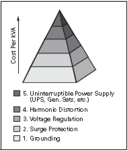
Figure 1.4-11. Power Quality Pyramid
1.Grounding
Grounding represents the foundation of a reliable power distribution system. Grounding and wiring problems can be the cause of up to 80% of all power quality problems. All other forms of power quality solutions are dependent upon good grounding procedures. The proliferation of communication and computer network systems has increased the need for proper grounding and wiring of AC and data/ communication lines. In addition to reviewing AC grounding and bonding practices, it is necessary to prevent ground loops from affecting the signal reference point.
2.Surge Protection
Surge protection devices (SPDs) are recommended as the next stage power quality solutions. NFPA, UL 96A, IEEE Emerald Book and equipment manufacturers recommend the use of surge protectors. The SPD shunt short duration voltage disturbances to ground, thereby preventing the surge from affecting electronic loads. When installed as part of the facility-wide design, SPDs are cost-effective compared to all other solutions (on a $/kVA basis).
The IEEE Emerald Book recommends the use of a two-stage protection concept. For large surge currents, diversion is best accomplished in two stages: the first diversion should be performed at the service entrance to the building. Then, any residual voltage resulting from the action can be dealt with by a second protective device at the power panel of the computer room (or other critical loads). Combined, the two stages of protection at the service entrance and branch panel locations reduce the IEEE 62.41 recommended test wave (C3–20 kV, 10 kA) to less than 200 V voltage, a harmless disturbance level for 120 V rated sensitive loads. If only building entrance feeder protection were provided, the let- through voltage will be approximately 950 V in a 277/480 V system exposed to induced lightning surges. This level of let-through voltage can cause degradation or physical damage of most electronic loads.
Wherever possible, consultants, specifiers and application engineers should ensure similar loads are fed from the same source. In this way, disturbance-generating loads are separated from electronic circuits affected by power disturbances. For example, motor loads, HVAC systems and other linear loads should be separated from the sensitive process control and computer systems. The most effective and economic solution for protecting a large number of loads is to install parallel SPDs at the building service entrance feeder and panel board locations. This reduces the cost of protection for multiple sensitive loads.
3.Voltage Regulation
Voltage regulation (i.e., sags or over- voltage) disturbances are generally site- or load-dependent. A variety of mitigating solutions are available depending upon the load sensitivity, fault duration/magnitude and the specific problems encountered. It is recommended to install monitoring equipment on the AC power lines to assess the degree and frequency of occurrences of voltage regulation problems. The captured data will allow for the proper solution selection.
4.Harmonics Distortion, Harmonics and Nonlinear Loads
Until recently, most electrical loads were linear. Linear loads draw the full sine wave of electric current at its 60 cycle (Hz) fundamental frequency—Figure 1.4-16 shows balance single-phase, linear loads. As the figure shows, little or no current flows in the neutral conductor when the loads are non- linear and balanced. With the arrival of nonlinear electronic loads, where the AC voltage is converted to a DC voltage, harmonics are created because of the use of only part of the AC sine wave. In this conversion from AC to DC, the electronics are turned on in the 60 cycle wave at a given point in time to obtain the required DC level. The use of only part of the sign wave causes harmonics. It is important to note that the current distortion caused by loads such as rectifiers or switch mode power supplies causes the voltage distortion. That voltage distortion is caused by distorted currents flowing through an impedance. The amount of voltage distortion depends on:
• System impedance
• Amount of distorted current
Devices that can cause harmonic disturbances include rectifiers, thrusters and switching power supplies, all of which are nonlinear. Further, the proliferation of electronic equipment such as computers, UPS systems, variable speed drives, programmable logic controllers, and the like: non-linear loads have become a significant part of many installations. Other types of harmonic-producing loads include arcing devices (arc furnaces, fluorescent lights) and iron core storable devices (transformers, especially during energization).
Nonlinear load currents vary widely from a sinusoidal wave shape; often they are discontinuous pulses. This means that nonlinear loads are extremely high in harmonic content. Triplen harmonics are the 3rd, 9th, 15th,…harmonics. Further, triplen harmonics are the most damaging to an electrical system because these harmonics on the A-phase, B-phase and C-phase are in sequence with each other. Meaning, the triplen harmonics present on the three phases add together in the neutral, as shown in Figure 1.4-17, rather than cancel each other out, as shown in Figure 1.4-16. Odd non-triplen harmonics are classified as “positive sequence” or “negative sequence” and are the 1st, 5th, 7th, 11th, 13th, etc. In general, as the order of a harmonic gets higher, its amplitude becomes smaller a percentage of the fundamental frequency.

Figure 1.4-16. Balanced Neutral Current Equals Zero
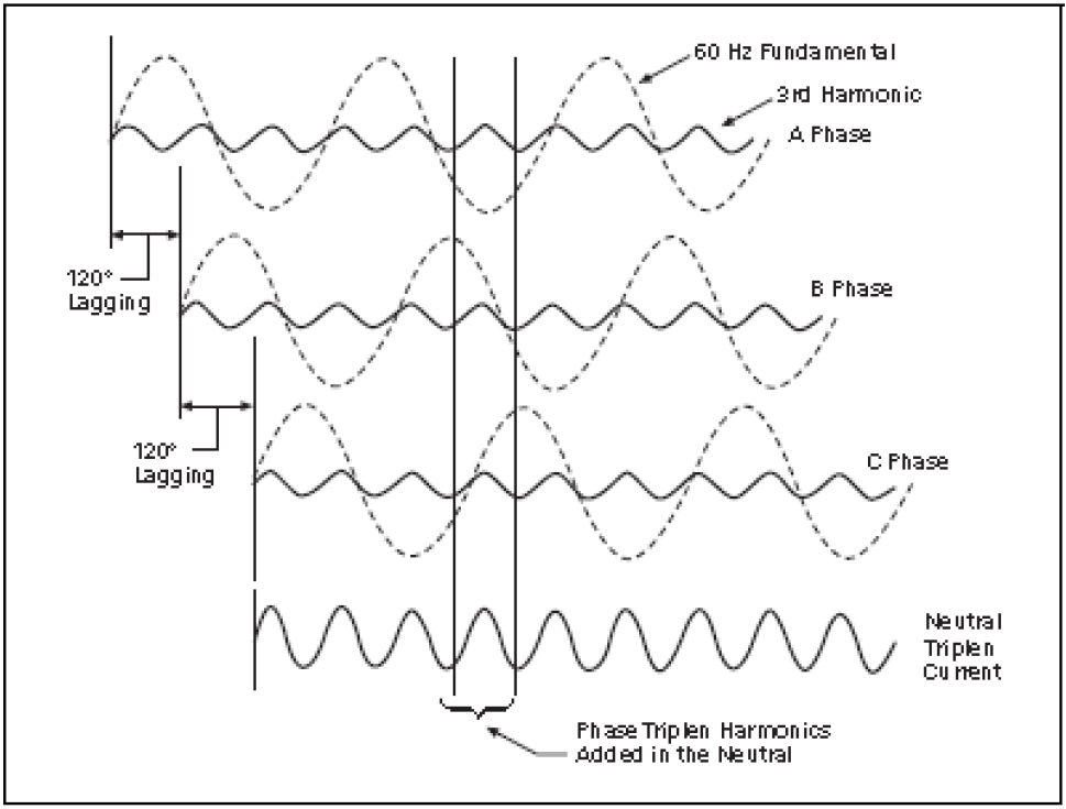
Figure 1.4-17. Unbalanced Single-Phase Loads with Triplen Harmonics
Harmonic Issues
Harmonic currents perform no work and result in wasted electrical energy that may over burden the distribution system. This electrical overloading may contribute to preventing an existing electrical distribution system from serving additional future loads.
In general, harmonics present on a distribution system can have the following detrimental effects:
- Overheating of transformers and rotating equipment.
- Increased hysteresis losses.
- Decreased kVA capacity.
- Overloading of neutral.
- Unacceptable neutral-to-ground voltages.
- Distorted voltage and current waveforms.
- Failed capacitor banks.
- Breakers and fuses tripping.
- Double or ever triple sized neutrals to defy the negative effects of triplen harmonics.
In transformers, generators and uninterruptible power supplies (UPS) systems, harmonics cause overheating and failure at loads below their ratings because the harmonic currents cause greater heating than standard 60 Hz current. This results from increased eddy current losses, hysteresis losses in the iron cores, and conductor skin effects of the windings. In addition, the harmonic currents acting on the impedance of the source cause harmonics in the source voltage, which is then applied to other loads such as motors, causing them to overheat. The harmonics also complicate the application of capacitors for power factor correction. If, at a given harmonic frequency, the capacitive impedance equals the system reactive impedance, the harmonic voltage and current can reach dangerous magnitudes. At the same time, the harmonics create problems in the application of power factor correction capacitors, they lower the actual power factor. The rotating meters used by the utilities for watthour and various measurements do not detect the distortion component caused by the harmonics. Rectifiers with diode front ends and large DC side capacitor banks have displacement power factor of 90% to 95%. More recent electronic meters are capable of metering the true kVA hours taken by the circuit.
Single-phase power supplies for computer and fixture ballasts are rich in third harmonics and their odd multiples.
Even with the phase currents perfectly balanced, the harmonic currents in the neutral can total 173% of the phase current. This has resulted in overheated neutrals. The Information Technology Industry Council (ITIC) formerly known as CBEMA, recommends that neutrals in the supply to electronic equipment be oversized to at least 173% of the ampacity of the phase conductors to prevent problems. ITIC also recommends derating transformers, loading them to no more than 50% to 70% of their nameplate kVA, based on a rule-of-thumb calculation, to compensate for harmonic heating effects. In spite of all the concerns they cause, nonlinear loads will continue to increase. Therefore, the design of nonlinear loads and the systems that supply them will have to be designed so that their adverse effects are greatly reduced. Table 1.4-4 shows the typical harmonic orders from a variety of harmonic generating sources.
Table 1.4-4. Source and Typical Harmonics
| Source | Typical Harmonics |
|---|---|
| 6-pules rectifier 12-pulse rectifier 18-pulse rectifier | 5, 7, 11, 13, 17, 19 … 11, 13, 23, 25 … 17, 19, 35, 37 … |
| Switch-mode power supply Fluorescent lights Arcing devices Transformer energization | 3, 5, 7, 9, 11, 13 … 3, 5, 7, 9, 11, 13 … 2, 3, 4, 5, 7 … 2, 3, 4 |
Total Harmonic Distortion
Revised standard IEEE 519-1992 indicates the limits of current distortion allowed at the PCC (Point of Common Coupling) point on the system where the current distortion is calculated, usually the point of connection to the utility or the main supply bus of the system. The standard also covers the harmonic limits of the supply voltage from the utility or cogenerators.
Table 1.4-5. Low Voltage System Classification and Distortion Limits for 480 V Systems
| Class | C | AN | DF |
|---|---|---|---|
| Special application General system Dedicated system | 10 5 2 | 16,400 22,800 36,500 | 3% 5% 10% |
Table 1.4-6. Utility or Cogenerator Supply Voltage Harmonic Limits
| Voltage Range | 23kV – 69kV | 69kV – 138kV | >138kV |
|---|---|---|---|
| Maximum individual harmonic | 3.0% | 1.5% | 1.0% |
| Total harmonic distortion | 5.0% | 2.5% | 1.5% |
Percentages are Vh / V1 x 100 for each harmonic and
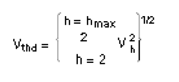
It is important for the system designer to know the harmonic content of the utility’s supply voltage because it will affect the harmonic distortion of the system.
Table 1.4-7. Current Distortion Limits for General Distribution Systems (120– 69,000 V)
| Maximum Harmonic Current Distortion in Percent of IL |
| Individual Harmonic Order (Odd Harmonics) |
| ISC/IL | <11 | 11≤ h <17 | 17≤ h <23 | 23≤ h <35 | 35≤ h | TDD |
|---|---|---|---|---|---|---|
| <20 20<50 50<100 100<1000 >1000 | 4.0 7.0 10.0 12.0 15.0 | 2.0 3.5 4.5 5.5 7.0 | 1.5 2.5 4.0 5.0 6.0 | 0.6 1.0 1.5 2.0 2.5 | 0.3 0.5 0.7 1.0 1.4 | 5.0 8.0 12.0 15.0 20.0 |
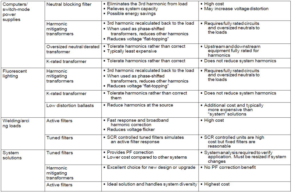
Harmonic Solutions
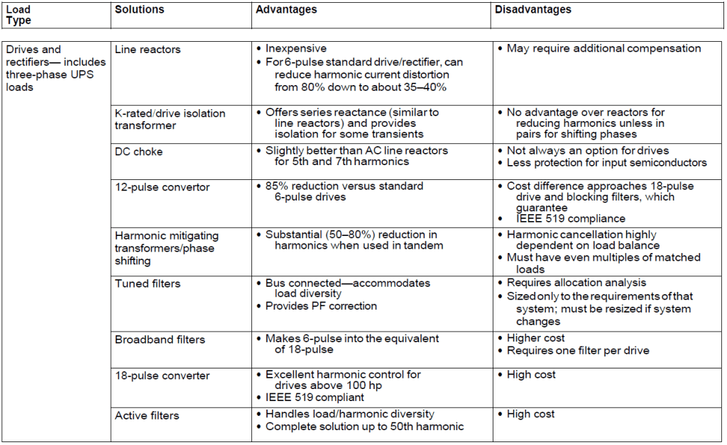
In spite of all the concerns nonlinear loads cause, these loads will continue to increase. Therefore, the design of nonlinear loads and the systems that supply them will need design so adverse harmonic effects are greatly reduced. Table 1.4-8 and depicts many harmonic solutions along with their advantages and disadvantages.
Table 1.4-8. Harmonic Solutions for Given Loads
5.Uninterruptible Power Systems (UPS)
The advent of solid-state semiconductors over 40 years ago, and their subsequent evolution to transistors, and the miniaturization of electronics into microprocessor over 25 years ago, has created numerous computation machines that assist us in every conceivable manner. These machines, and their clever configurations, whether they take the form of computers, appliance controls, fax machines, phone systems, computers of all sizes, server systems and server farms, emergency call centers, data processing at banks, credit companies, private company communication networks, government institutions and defense agencies, all rely on a narrow range of nominal AC power in order for these devices to work properly. Indeed, many other types of equipment also require that the AC electrical power source be at or close to nominal voltage and frequency. Disturbances of the power translate into failed processes, lost data, decreased efficiency and lost revenue.
The normal power source supplied by the local utility or provider is not stable enough over time to continuously serve these loads without interruption. It is possible that a facility outside a major metropolitan area served by the utility grid will experience outages of some nature 15–20 times in one year. Certain outages are caused by the weather, and others by the failure of the utility supply system due to equipment failures or construction interruptions. Some outages are only several cycles in duration, while others may be for hours at a time. In a broader sense, other problems exist in the area of power quality, and many of those issues also contribute to the failure of the supply to provide that narrow range of power to the sensitive loads mentioned above. Power quality problems take the form of any of the following: power failure, power sag, power surge, undervoltage, overvoltage, line noise, frequency variations, switching transients and harmonic distortion.
Regardless of the reason for outages and power quality problems, the sensitive loads cannot function normally without a backup power source, and in many cases, the loads must be isolated from the instabilities of the utility supply and power quality problems and given clean reliable power on a continuous basis, or be able to switch over to reliable clean electrical power quickly. Uninterruptible power supply (UPS) systems have evolved to serve the needs of sensitive equipment and can supply a stable source of electrical power, or switch to backup to allow for an orderly shutdown of the loads without appreciable loss of data or process. In the early days of main- frame computers, motor-generator sets provide isolation and clean power to the computers. They did not have deep reserves, but provided extensive ride-through capability while other sources of power (usually standby emergency engine generator sets) were brought to serve the motor-generator sets while the normal source of power was unstable or unavailable.
UPS systems have evolved along the lines of rotary types and static types of systems, and they come in many configurations, and even hybrid designs having characteristics of both types. The discussion that follows attempts to compare and contrast the two types of UPS systems, and give basic guidance on selection criteria. This discussion will focus on the medium, large and very large UPS systems required by users who need more than 10 kVA of clean reliable power.
*Mr. Nikola Zlatanov spent over 20 years working in the Capital Semiconductor Equipment Industry. His work at Gasonics, Novellus, Lam and KLA-Tencor involved progressing electrical engineering and management roles in disruptive technologies. Nikola received his Undergraduate degree in Electrical Engineering and Computer Systems from Technical University, Sofia, Bulgaria and completed a Graduate Program in Engineering Management at Santa Clara University. He is currently consulting for Fortune 500 companies as well as Startup ventures in Silicon Valley, California.

Great post.
LikeLike