Published by Nikola Zlatanov*
Ground Fault Protection
Article 230.95 of NEC requires ground- fault protection of equipment shall be provided for solidly grounded wye electrical services of more than 150 V to ground, but not exceeding 600 V phase-to-phase for each service disconnect rated 1000 A or more. The rating of the service disconnect shall be considered to be the rating of the largest fuse that can be installed or the highest continuous current trip setting for which the actual overcurrent device installed in a circuit breaker is rated or can be adjusted. The maximum allowable settings are: 1200 A pickup, 1 second or less trip delay at currents of 3000 A or greater. The characteristics of the ground-fault trip elements create coordination problems with downstream devices not equipped with ground fault protection. The National Electrical Code exempts fire pumps and continuous industrial processes from this requirement.
It is recommended that in solidly grounded 480/277 V systems where main breakers are specified to be equipped with ground fault trip elements that the feeder breakers be specified to be equipped with ground fault trip elements as well.
Suggested Ground Fault Settings
For the main devices:
A ground fault pickup setting equal to 20–30% of the main breaker rating but not to exceed 1200 A, and a time delay equal to the delay of the short- time element, but not to exceed 1 second.
For the feeder ground fault setting:
A setting equal to 20–30% of the feeder ampacity and a time delay to coordinate with the setting of the main (at least 6 cycles below the main). If the desire to selectively coordinate ground fault devices results in settings that do not offer adequate damage protection against arcing single line- ground faults, the design engineer should decide between coordination and damage limitation.
For low voltage systems with high- magnitude available short-circuit currents, common in urban areas and large industrial installations, several solutions are available. High interrupting Series C® molded case breakers, current-limiting circuit breakers, or current-limiting fuses, limiters integral with molded-case circuit breakers (TRI-PAC®) or mounted on power circuit breakers (MDSL) can be used to handle these large fault currents. To provide current limiting, these devices must clear the fault completely within the first half-cycle, limiting the peak current (Ip) and heat energy (I2t) let-through to considerably less than what would have occurred without the device. For a fully fusible system, rule-of-thumb fuse ratios or more accurate I2t curves can be used to provide selectivity and coordination. For fuse-breaker combinations, the fuse should be selected (coordinated) so as to permit the breaker to handle those overloads and faults within its capacity; the fuse should operate before or with the breaker only on large faults, approaching the interrupting capacity of the breaker, to minimize fuse blowing. Recently, unfused, truly current-limiting circuit breakers with interrupting ratings adequate for the largest systems (Type Series C, FDC, JDC, KDC, LDC and NDC frames or Type Current Limit-R®) have become available.
The Series G high performance, current-limiting circuit breaker series offers interrupting ratings to 200 kA. Frames are EGC, EGU, EGX, JGC, JGU, JGX, LGC, LGU and LGX.
Any of these current-limiting devices— fuses, fused breakers or current-limiting breakers—cannot only clear these large faults safely, but also will limit the Ip and I2t let-through significantly to prevent damage to apparatus downstream, extending their zone of protection. Without the current limitation of the upstream device, the fault current could exceed the with- stand capability of the downstream equipment. Underwriters Laboratories tests and lists these series combinations. Application information is available for combinations that have been tested and UL®-listed for safe operation downstream from MDSL, TRI-PAC, and Current Limit-R, or Series C breakers of various ratings, under high available fault currents.
Protective devices in electrical distribution systems may be properly coordinated when the systems are designed and built, but that is no guarantee that they will remain coordinated. System changes and additions, plus power source changes, frequently modify the protection requirements, sometimes causing loss of coordination and even increasing fault currents beyond the ratings of some devices. Consequently, periodic study of protective-device settings and ratings is as important for safety and preventing power outages as is periodic maintenance of the distribution system.
Grounding
Grounding encompasses several different but interrelated aspects of electrical distribution system design and construction, all of which are essential to the safety and proper operation of the system and equipment supplied by it. Among these are equipment grounding, system grounding, static and lightning protection, and connection to earth as a reference (zero) potential.
1.Equipment Grounding
Equipment grounding is essential to safety of personnel. Its function is to ensure that all exposed noncurrent- carrying metallic parts of all structures and equipment in or near the electrical distribution system are at the same potential, and that this is the zero reference potential of the earth. Equipment grounding is required by both the National Electrical Code (Article 250) and the National Electrical Safety Code regardless of how the power system is grounded. Equipment grounding also provides a return path for ground fault currents, permitting protective devices to operate. Accidental contact of an energized conductor of the system with an improperly grounded noncurrent-carry metallic part of the system (such as a motor frame or panelboard enclosure) would raise the potential of the metal object above ground potential. Any person coming in contact with such an object while grounded could be seriously injured or killed. In addition, current flow from the accidental grounding of an energized part of the system could generate sufficient heat (often with arcing) to start a fire. To prevent the establishment of such unsafe potential difference requires that (1) the equipment grounding conductor provide a return path for ground fault currents of sufficiently low impedance to prevent unsafe voltage drop, and (2) the equipment grounding conductor be large enough to carry the maximum ground fault current, without burning off, for sufficient time to permit protective devices (ground fault relays, circuit breakers, fuses) to clear the fault. The grounded conductor of the system (usually the neutral conductor), although grounded at the source, must not be used for equipment grounding.
The equipment grounding conductor may be the metallic conduit or raceway of the wiring system, or a separate equipment grounding conductor, run with the circuit conductors, as permitted by NEC. If a separate equipment grounding conductor is used, it may be bare or insulated; if insulated, the insulation must be green, green with yellow stripe or green tape. Conductors with green insulation may not be used for any purpose other than for equipment grounding. The equipment grounding system must be bonded to the grounding electrode at the source or service; however, it may be also connected to ground at many other points. This will not cause problems with the safe operation of the electrical distribution system. Where computers, data processing, or microprocessor- based industrial process control systems are installed, the equipment grounding system must be designed to minimize interference with their proper operation. Often, isolated grounding of this equipment, or isolated electrical supply systems are required to protect microprocessors from power system “noise” that does not in any way affect motors or other electrical equipment.
Such systems must use single-point ground concept to minimize “noise” and still meet the NEC requirements. Any separate isolated ground mat must be tied to the rest of the facility ground mat system for NEC compliance.
2.System Grounding
System grounding connects the electrical supply, from the utility, from transformer secondary windings, or from a generator, to ground. A system can be solidly grounded (no intentional impedance to ground), impedance grounded (through a resistance or grounded (with no intentional connection to ground.
3.Medium Voltage System: Grounding
Table 1.4-1. Features of Ungrounded and Grounded Systems (from ANSI C62.92)

Grounding/Ground Fault Protection
Because the method of grounding affects the voltage rise of the un-faulted phases above ground, ANSI C62.92 classifies systems from the point of view of grounding in terms of a coefficient of grounding This same standard also defines systems as effectively grounded when COG ð .8 such a system would have X0 /X1 ð 3.0 and R0 /X1 ð 1.0. Any other grounding means that does not satisfy these conditions at any point in a system is not effectively grounded. The aforementioned definition is of significance in medium voltage distribution systems with long lines and with grounded sources removed during light load periods so that in some locations in the system the X0 /X1, R0 /X1 may exceed the defining limits.
Other standards (cable and lightning arrester) allow the use of 100% rated cables and arresters selected on the basis of an effectively grounded system only where the criteria in the above are met. In effectively grounded system the line-to-ground fault current is high and there is no significant voltage rise in the un-faulted phases. With selective ground fault isolation the fault current should be at least 60% of the three-phase current at the point of fault. Damage to cable shields must be checked. Although this fact is not a problem except in small cables, it is a good idea to supplement the cable shields returns of ground fault current to prevent damage, by installing an equipment grounding conductor. The burdens on the current transformers must be checked also (for saturation considerations), where residually connected ground relays are used and the current transformers supply current to phase relays and meters. If ground sensor current transformers type) are used they must be of high burden capacity.
Table 1.4-1. Features of Ungrounded and Grounded Systems (Continued)


Table 1.4-2 taken from ANSI-C62.92 indicates the characteristics of the various methods of grounding.
Reactance Grounding
It is generally used in the grounding of the neutrals of generators directly connected to the distribution system bus, in order to limit the line-to-ground fault to somewhat less than the three- phase fault at the generator terminals. If the reactor is so sized, in all probability the system will remain effectively grounded.
Resistance Grounded
Medium voltage systems in general should be low resistance grounded. The ground fault is typically limited to about 200–400 A but less than 1000 A (a cable shield consideration). With a properly sized resistor and relaying application, selective fault isolation is feasible. The fault limit provided has a bearing on whether residually connected relays are used or ground sensor current transformers are used for ground fault relaying. In general, where residually connected ground relays are used (51N), the fault current at each grounded source should not be limited to less than the current transformers rating of the source. This rule will provide sensitive differential protection for wye-connected generators and transformers against line-to-ground faults near the neutral. Of course, if the installation of ground fault differential protection is feasible, or ground sensor current transformers are used, sensitive differential relaying in resistance grounded system with greater fault limitation is feasible. In general, ground sensor current transformers (zero sequence) do not have high burden capacity. Resistance grounded systems limit the circulating currents of triple harmonics and limit the damage at the point of fault. This method of grounding is not suitable for line-to-neutral connection of loads. On medium voltage systems, 100% cable insulation is rated for phase-to- neutral voltage. If continued operation with one phase faulted to ground is desired, increased insulation thickness is required. For 100% insulation, fault clearance is recommended within one minute; for 133% insulation, one hour is acceptable; for indefinite operation, as long as necessary, 173% insulation is required.
Table 1.4-2. Characteristics of Grounding
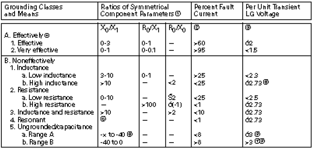
- Values of the coefficient of grounding (expressed as a percentage of maximum phase-to-phase voltage) corresponding to various combinations of these ratios are shown in the ANSI C62.92 Appendix figures. Coefficient of grounding affects the selection of arrester ratings.
- Ground-fault current in percentage of the three-phase short-circuit value.
- Transient line-to-ground voltage, following the sudden initiation of a fault in per unit of the crest of the prefault line-to-ground operating voltage for a simple, linear circuit.
- In linear circuits, Class A1 limits the fundamental line-to-ground voltage on an un-faulted phase to 138% of the prefault voltage; Class A2 to less than 110%.
- See ANSI 62.92 para. 7.3 and precautions given in application sections.
- Usual isolated neutral (ungrounded) system for which the zero-sequence reactance is capacitive (negative).
- Same as NOTE (6) and refer to ANSI 62.92 para. 7.4. Each case should be treated on its own merit.
- Under restriking arcing ground fault conditions (e.g., vacuum breaker interrupter operation),this value can approach 500%.
- Under arcing ground fault conditions, this value can easily reach 700%, but is essentially unlimited.
Grounding Point
The most commonly used grounding point is the neutral of the system or the neutral point created by means of a zigzag or a wye-broken delta grounding transformer in a system that was operating as an ungrounded delta system. In general, it is a good practice that all source neutrals be grounded with the same grounding impedance magnitude. However, neutrals should not be tied together to a single resistor. Where one of the medium voltage sources is the utility, their consent for impedance grounding must be obtained.
The neutral impedance must have a voltage rating at least equal to the rated line-to-neutral voltage class of the system. It must have at least a 10-second rating equal to the maximum future line-to-ground fault current and a continuous rating to accommodate the triple harmonics that may be present.
4.Low Voltage System: Grounding
Solidly grounded three-phase systems (Figure 1.4-2) are usually wye- connected, with the neutral point grounded. Less common is the “red- leg” or high-leg delta, a 240 V system supplied by some utilities with one winding center-tapped to provide 120 V to ground for lighting. This 240 V, three- phase, four-wire system is used where 120 V lighting load is small compared to 240 V power load, because the installation is low in cost to the utility. A corner-grounded three-phase delta system is sometimes found, with one phase grounded to stabilize all voltages to ground. Better solution are available for new installations.
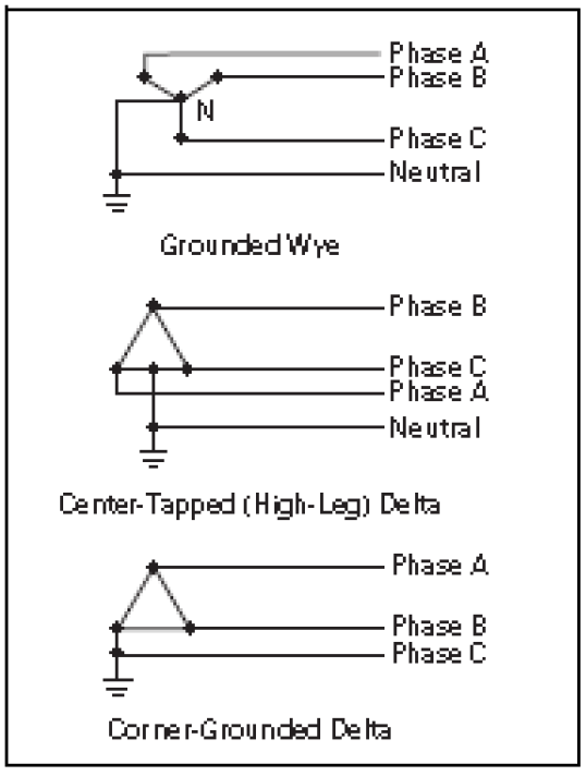
Figure 1.4-2. Solidly Grounded Systems
Lightning and Surge Protection
Physical protection of buildings from direct damage from lightning is beyond the scope of this section. Requirements will vary with geographic location, building type and environment, and many other factors (see IEEE/ANSI Standard 142, Grounding of Industrial and Commercial Power Systems). Any lightning protection system must be grounded, and the lightning protection ground must be bonded to the electrical equipment grounding system.
Grounding Electrodes
At some point, the equipment and system grounds must be connected to the earth by means of a grounding electrode system. Outdoor substations usually use a ground grid, consisting of a number of ground rods driven into the earth and bonded together by buried copper conductors. The required grounding electrode system for a building is spelled out in the NEC Article 250.
The preferred grounding electrode is a metal underground water pipe in direct contact with the earth for at least 10 ft (3 m). However, because under- ground water piping is often plastic outside the building, or may later be replaced by plastic piping, the NEC requires this electrode to be supplemented by and bonded to at least one other grounding electrode, such as the effectively grounded metal frame of the building, a concrete-encased electrode, a copper conductor ground ring encircling the building, or a made electrode such as one or more driven ground rods or a buried plate. Where any of these electrodes are present, they must be bonded together into one grounding electrode system. One of the most effective grounding electrodes is the concrete-encased electrode, sometimes called the Ufer ground, named after the man who developed it. It consists of at least 20 ft (6 m) of steel reinforcing bars or rods not less than 1/2 inches (12.7 mm) in diameter, or at least 20 ft (6 m) of bare copper conductor, size No. 4 AWG or larger, encased in at least 2 inches (50.8 mm) of concrete. It must be located within and near the bottom of a concrete foundation or footing that is in direct contact with the earth. Tests have shown this electrode to provide a low-resistance earth ground even in poor soil conditions.
The electrical distribution system and equipment ground must be connected to this grounding electrode system by a grounding electrode conductor. All other grounding electrodes, such as those for the lightning protection system, the telephone system, television antenna and cable TV system grounds, and computer systems, must be bonded to this grounding electrode system.
*Mr. Nikola Zlatanov spent over 20 years working in the Capital Semiconductor Equipment Industry. His work at Gasonics, Novellus, Lam and KLA-Tencor involved progressing electrical engineering and management roles in disruptive technologies. Nikola received his Undergraduate degree in Electrical Engineering and Computer Systems from Technical University, Sofia, Bulgaria and completed a Graduate Program in Engineering Management at Santa Clara University. He is currently consulting for Fortune 500 companies as well as Startup ventures in Silicon Valley, California.
