Application Note
Published by H. Markiewicz and A. Klajn, November 2014
ECI Publication No. Cu0120
Document Issue Control Sheet
| Document Title: | Application Note – Earthing Systems: Fundamentals of Calculation and Design |
| Publication No: | Cu0120 |
| Issue: | 03 |
| Release: | June 2003 |
| Author(s): | H. Markiewicz and A. Klajn |
| Reviewer(s): | D. Chapman, S. Fassbiner |
Document History
| Issue | Date | Purpose |
|---|---|---|
| 1 | June 2003 | Initial publication |
| 2 | November 2011 | Upgrade by David Chapman for adoption into the Good Practice Guide |
| 3 | November 2014 | Review with minor adaptations |
Disclaimer
While this publication has been prepared with care, European Copper Institute and other contributors provide no warranty with regards to the content and shall not be liable for any direct, incidental or consequential damages that may result from the use of the information or the data contained.
SUMMARY
This Application Note discusses the principles of earthing electrode design with particular emphasis on earth potential distribution of various electrode geometries.
The electrical properties of the ground and variations according to type and moisture content are discussed. The equation for calculation of the earthing resistance and potential distribution for an idealized hemispherical earth electrode is derived. The concepts of step and touch voltages are discussed and the effect of earthing electrode geometry shown.
The concepts developed here are the basis for the practical guidance given in the Application Note Earthing Systems: Basic Constructional Aspects.
INTRODUCTION
The concept of modern integrated earthing systems was introduced in the Application Note Integrated Earthing Systems. In an integrated earthing system, all of the different earthing functions – lightning and short circuit protection, safety and electromagnetic compatibility – are designed and implemented as one entity.
This Application Note is concerned only with the part of an integrated system that is buried in the ground, called the earth or ground electrode, and covers fundamental aspects of design and calculation. A further Application Note, Earthing systems: Basic Constructional Aspects gives practical guidance on the design of ground electrodes and the calculation of their properties.
The earthing system is an essential part of power networks at both high- and low-voltage levels. A good earthing system is required for:
- Protection of buildings and installations against lightning
- Safety of human and animal life by limiting touch and step voltages to safe values
- Electromagnetic compatibility (EMC) i.e. limitation of electromagnetic disturbances
- Correct operation of the electricity supply network and to ensure good power quality
In modern practice these functions are provided by a single system designed to fulfill the requirements of all of them. Although some elements of an earthing system may be provided to fulfill a specific purpose, they are nevertheless part of one single system – standards require that all earthing measures within an installation are bonded together, forming one system.
BASIC DEFINITIONS [1, 2]
Earthing or earthing system is the total of all means and measures by which part of an electrical circuit, accessible conductive parts of electrical equipment (exposed conductive parts) or conductive parts in the vicinity of an electrical installation (extraneous conductive parts) are connected to earth.
Earth or ground electrode is a metal conductor, or a system of interconnected metal conductors, or other metal parts acting in the same manner, embedded in the ground and electrically connected to it, or embedded in the concrete, which is in contact with the earth over a large area (e.g. foundation of a building).
Earthing conductor is a conductor which connects a part of an electrical installation, exposed conductive parts or extraneous conductive parts to an earth electrode or which interconnects earth electrodes. The earthing conductor is laid above the soil or, if it is buried in the soil, is insulated from it.
Reference earth is that part of the ground, particularly on the earth surface, located outside the sphere of influence of the considered earth electrode, i.e. between two random points at which there is no perceptible voltages resulting from the earthing current flow through this electrode. The potential of reference earth is always assumed to be zero.
Earthing voltage (earthing potential), VE, is the voltage occurring between the earthing system and reference earth at a given value of the earth current flowing through this earthing system.
Earth resistivity ρ (specific earth resistance) is the resistance, measured between two opposite faces, of a one-metre cube of earth (See Figure 1). The earth resistivity is expressed in Ωm.
Earth surface potential, Vx, is the voltage between a point x on the earth’s surface and reference earth.
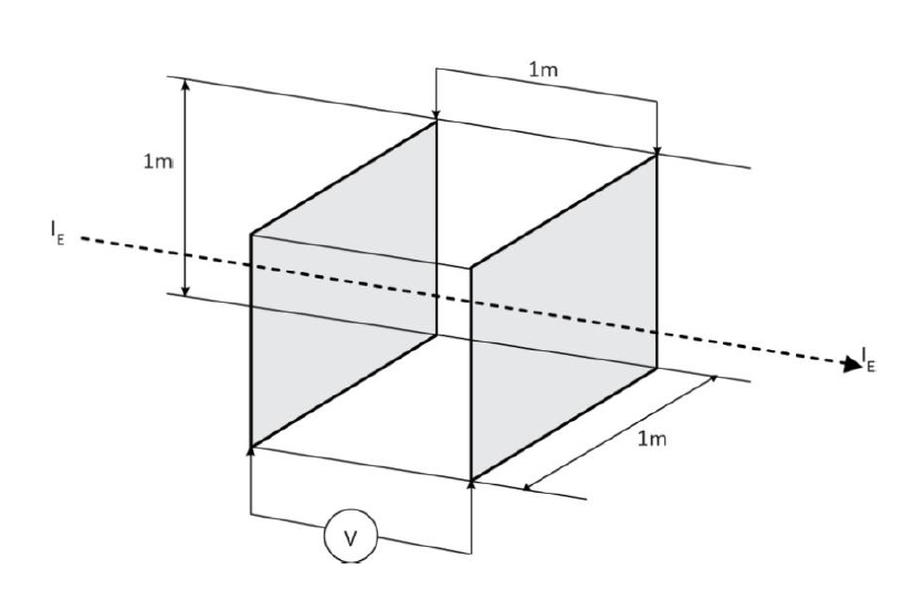
Figure 1 – Diagram illustrating the physical sense of earth resistivity ρ.
ELECTRICAL PROPERTIES OF THE GROUND
The electrical properties of the ground are characterised by the earth resistivity ρ. In spite of the relatively simple definition of ρ given above, the determination of its value is often a complicated task for two main reasons:
- The ground does not have a homogenous structure, but is formed of layers of different materials
- The resistivity of a given type of ground varies widely and is very dependent on moisture content
The calculation of the earthing resistance requires a good knowledge of the soil properties, particularly of its resistivity ρ. Thus, the large variation in the value of ρ is a problem. In many practical situations, a homogenous ground structure will be assumed with an average value of ρ, which must be estimated on the basis of soil analysis or by measurement. There are established techniques for measuring earth resistivity. One important point is that the current distribution in the soil layers used during measurement should simulate that for the final installation. Consequently, measurements must always be interpreted carefully. Where no information is available about the value of ρ it is usually assumed ρ = 100 Ωm. However, as Table 1 indicates, the real value can be very different, so acceptance testing of the final installation, together with an assessment of likely variations due to weather conditions and over lifetime, must be undertaken

Table 1 – Ground resistivity ρ for various kinds of the soil and concrete [2, 4].
The other problem in determining soil resistivity is the moisture content, which can change over a wide range, depending on geographical location and weather conditions, from a low percentage for desert regions up to about 80 % for swampy regions. The earth resistivity depends significantly on this parameter. Figure 2 illustrates the relationship between resistivity and humidity for clay. One can see here that, for soil humidity values higher than 30 %, changes of ρ are very slow and not significant. However, when the ground is dry, i.e. values lower than 20 %, the resistivity increases very rapidly.
In regions with a temperate climate, for example in European countries, the earthing resistance changes according to the season of the year, due to dependence of soil humidity on earth resistivity. For Europe, this dependence has an approximate sine form, where the maximum value of earthing resistance occurs in February and the minimum value in August. The average value occurs in May and November. The amplitude in February is approximately 30 % larger than average, while in August it is about 30 % smaller than the average [4].
It must be remembered that the effect of freezing is similar to that of drying – the resistivity increases significantly.
For these reasons the calculations of earth resistance and the design of electrodes can only be performed up to a limited level of accuracy.
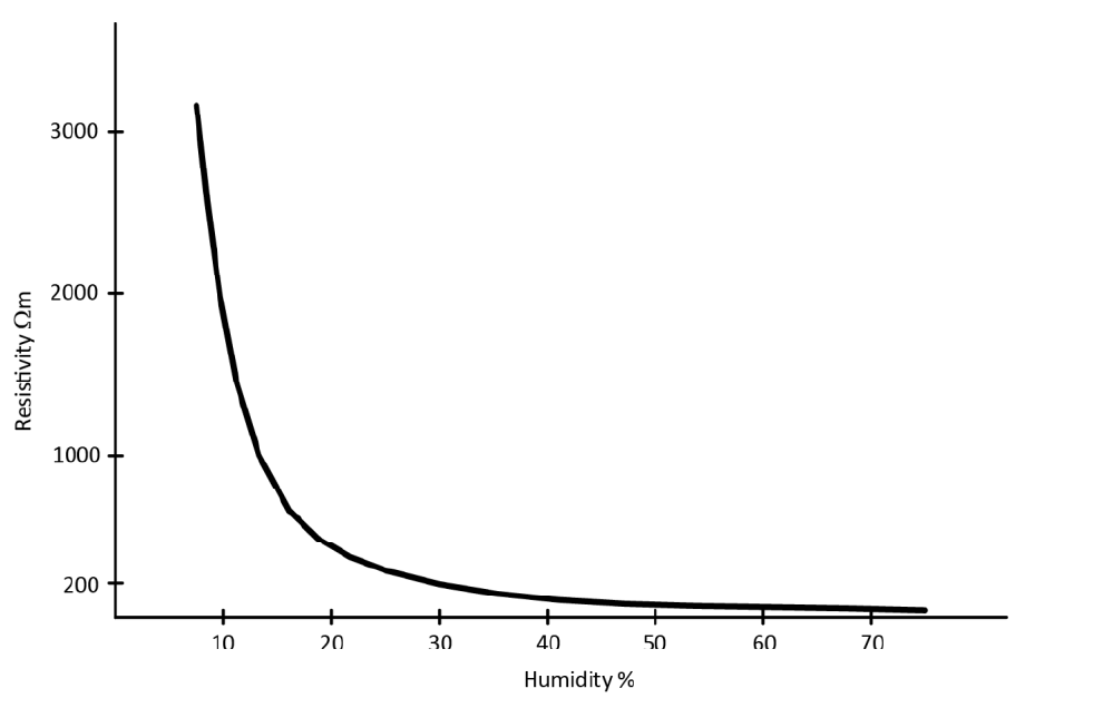
Figure 2 – Earth resistivity ρ of clay as function of soil humidity.
ELECTRICAL PROPERTIES OF THE EARTHING SYSTEM
The electrical properties of earthing depend essentially on two parameters:
- Earthing resistance
- Configuration of the earth electrode
Earthing resistance determines the relation between earth voltage VE and the earth current value. The configuration of the earth electrode determines the potential distribution on the earth surface, which occurs as a result of current flow in the earth. The potential distribution on the earth surface is an important consideration in assessing the degree of protection against electric shock because it determines the touch and step potentials. These questions are discussed briefly below.
The earthing resistance has two components:
- Dissipation resistance RD, which is the resistance of the earth between the earth electrode and the reference earth.
- Resistance RL of the metal parts of the earth electrode and of the earthing conductor.
The resistance RL is usually much smaller than the dissipation resistance RD. Thus, usually the earthing resistance is estimated to be equal to the dissipation resistance RD. In the literature, ‘earthing resistance’ usually refers to the dissipation resistance.
Any earth connection made available by the supplier appears in parallel with the locally provided earth and may well be expected to have lower impedance at fundamental and harmonic frequencies than the local earth. However, the availability and characteristics of this path are beyond the designer’s control and hence should not be considered in the design of the earthing system which should be adequate for the required purpose in its own right.
EARTHING RESISTANCE AND POTENTIAL DISTRIBUTION
In AC circuits one must consider essentially the impedance of an earthing ZE, which is the impedance between the earthing system and the reference earth at a given operating frequency. The reactance of the earthing system is the reactance of the earthing conductor and of metal parts of the earth electrode. At low frequencies – the supply frequency and associated harmonics – reactance is usually negligible in comparison to earthing resistance, but must be taken into account for high frequencies such as lightning transients. Thus, for low frequencies, it is assumed that the earthing impedance ZE is equal the dissipation resistance RD, which is in turn assumed to be approximately equal to the earthing resistance, R:

The earthing resistance R of an earth electrode depends on the earth resistivity ρ as well as the electrode geometry. In order to achieve low values of R the current density flowing from the electrode metal to the earth should be low, i.e. the volume of earth through which the current flows should be as large as possible. Once the current flows from metal to earth it spreads out, reducing current density. If the electrode is physically small, e.g., a point, this effect is large, but is very much reduced for a plate where spreading is only effective at the edges. This means that rod, pipe, or wire electrodes have a much lower dissipation resistance than, for example, a plate electrode with the same surface area. Moreover, it is well documented in the literature that dc- and ac-induced corrosion increases with current density. Low current density extends electrode life.
The calculation of earthing resistance is usually performed under the assumptions that the ground is boundless and of uniform structure with a given value of resistivity. It is possible to determine exact equations for earthing resistance but, in practice, their usefulness is very limited, especially in case of complex and meshed earth electrodes where the mathematical relations become very complicated. Furthermore, even a small inaccuracy in value of the resistivity has a significant influence on the actual earthing resistance of meshed earth electrodes and it is often very difficult to determine the earth resistivity with the accuracy required. Because of this, exact theoretical equations of earthing resistance are usually used only for simple structures of earth electrodes in order to illustrate the relationship between the earth voltage, earth potential distribution and the earth current. For extended and meshed earth electrodes, approximations of earth resistance are used.
A basic model of the earth electrode configuration, used for illustrating the fundamental electrical properties, is a hemisphere embedded in the ground surface (Figure 3).
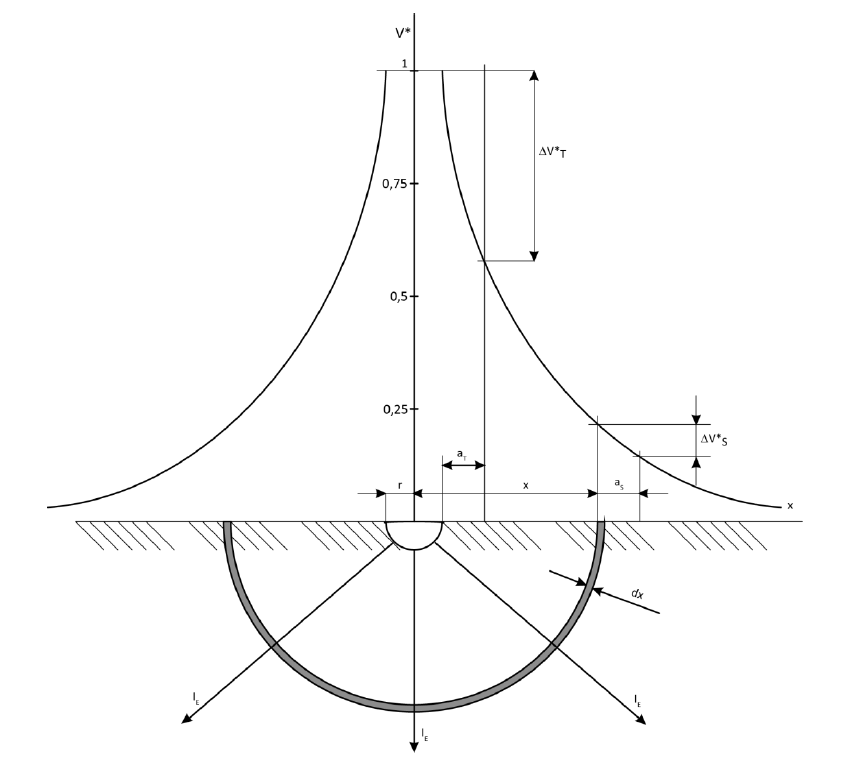
Figure 3 – Illustration of a notional hemispherical earth electrode, showing parameters required to calculate the earthing resistance and potential distribution on the ground surface (with ρ = const):
- r – electrode radius
- x – destination from the centre of the electrode
- aT, aS – touch and step distances respectively
- V* – relative value of the potential distribution
- ΔV*T, ΔV*S – touch and step voltages respectively
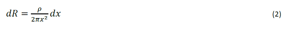
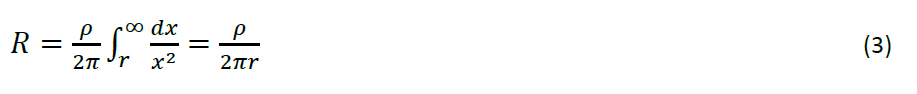
The earth current flowing to such an electrode is assumed to flow radially to the earth. The surface of the hemisphere, as well as all hemisphere cross sections, dx, of the ground, are assumed to be equipotential, and the current lines are therefore perpendicular to these surfaces. Under these conditions the resistance of the hemisphere-ground-sheath of thickness dx and the radius x is expressed as follows (with ρ assumed constant):
The resistance of the hemisphere-earth electrode is given by:
The earth resistance depends significantly on how deep the electrode is sunk in the ground. This is because the moisture content is higher and more stable for deeper ground layers than for shallow layers. Layers near the surface are influenced more by seasonal and short-term weather variations and are subject to freezing. This problem is illustrated in Figure 4, for a vertical rod earth electrode, where one can see the considerable reduction of earthing resistance as the depth of penetration of a rod electrode increases. However, it is not always possible to place electrodes at the preferred depth for geological reasons, for example, where there are rocks or obstructions close to the surface or where the electrode system covers a large area.
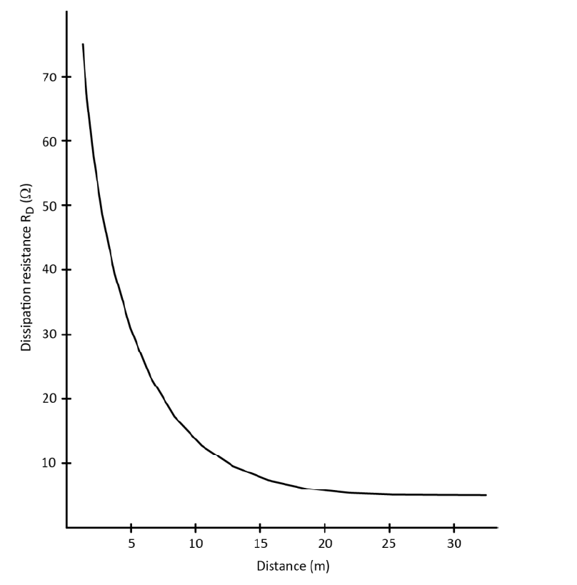
Figure 4 – Example of dissipation resistance of a vertical rod earth electrode as a function of the depth d.
One can distinguish the following types of earth electrodes:
- Simple surface earth electrodes in the form of horizontally placed strip or wire either as a single ended strip or a ring
- Meshed electrodes, constructed as a grid placed horizontally at shallow depth
- Cable with exposed metal sheath or armour which behaves similarly to a strip-type earth electrode
- Foundation earth electrodes formed from conductive structural parts embedded in concrete foundation providing a large area contact with the earth
- Rod electrodes which can consist of a pipe, rod, etcetera, and are driven or buried to a depth greater than 1 m and usually from 3 m to 30 m or more
The first four arrangements are surface earth electrodes, which usually consist of strip wire or band arranged as radial, ring or meshed electrodes, or a combination of these embedded at shallow depths of up to about 1 m. An important advantage of these constructions is the favourable surface potential distribution. Rod electrodes belong to so called deep earth electrodes, the advantage of these is that they pass through soil layers of different conductivity and are particularly useful in places where the shallow layers have poor conductivity. In this way it is easy to obtain an expected electrode resistance (Figure 4). Another advantage of rod electrodes is that they can be installed in places where there is a limited surface area available to install the electrode. However, surface potential distribution of rod electrodes is unfavourable, so in practice a combination of rod and surface earth electrodes are also used, in order to obtain both a good resistance and desirable surface potential distribution. Surface potential distribution is subject of the next section.
More detailed descriptions and basic equations concerning earth resistance of typical earth electrodes mentioned are given in the Application Note Earthing systems – Basic Constructional Aspects.
EARTHING VOLTAGE AND EARTH SURFACE POTENTIAL DISTRIBUTION
The earthing voltage and the distribution of the earth surface potential, arising from fault current flowing in the earthing system, are important parameters for protection against electric shock. The basic relations are shown on the earth model presented in the Figure 3.
The potential of any point located at distance x from the middle of earth electrode, in which earth current IE flows, can be formulated with the following equation:

and its relative value:

where VE is the earthing voltage, which is equal to the earthing potential (assuming that the potential of the reference earth is equal to zero). The earthing potential can be described as follows:
The potential difference between two points on the earth surface: one at distance x and other at distance x + aS, where aS is assumed to be equal to 1 metre, illustrates the step potential ΔVS, i.e. earth surface potential existing between two feet, when a person stands at that position on the earth surface:
and its relative value

where x ≥ r.
A similar relationship can be described for any other distances x and a. Particularly for x = r and a = aT = 1 m, formula (6) enables the calculation of the touch voltage, i.e. the voltage between a palm and a foot of a person who is just touching the earth electrode or metal parts connected to it:

and its relative value:

A practical illustration of touch and step voltages is shown in Figure 5. Persons A and B are subject to the touch potential while person C is subject to the step potential. The touch voltage VT is sometimes in the literature differentiated from the shocking touch voltage VTS (and step voltage VS from the shocking step voltage VSS).Voltages VT and VS are the pure values resulting from the potential distribution, whereas VTS and VSS consider the small changes in potential distribution caused by flowing of shocking current – i.e. including the distorting effect of the current flow through the person. In practice the difference between VS and VSS or VT and VTS is usually small, so that the same values for the respective potentials are assumed: VS ≈ VSS and VT ≈ VTS
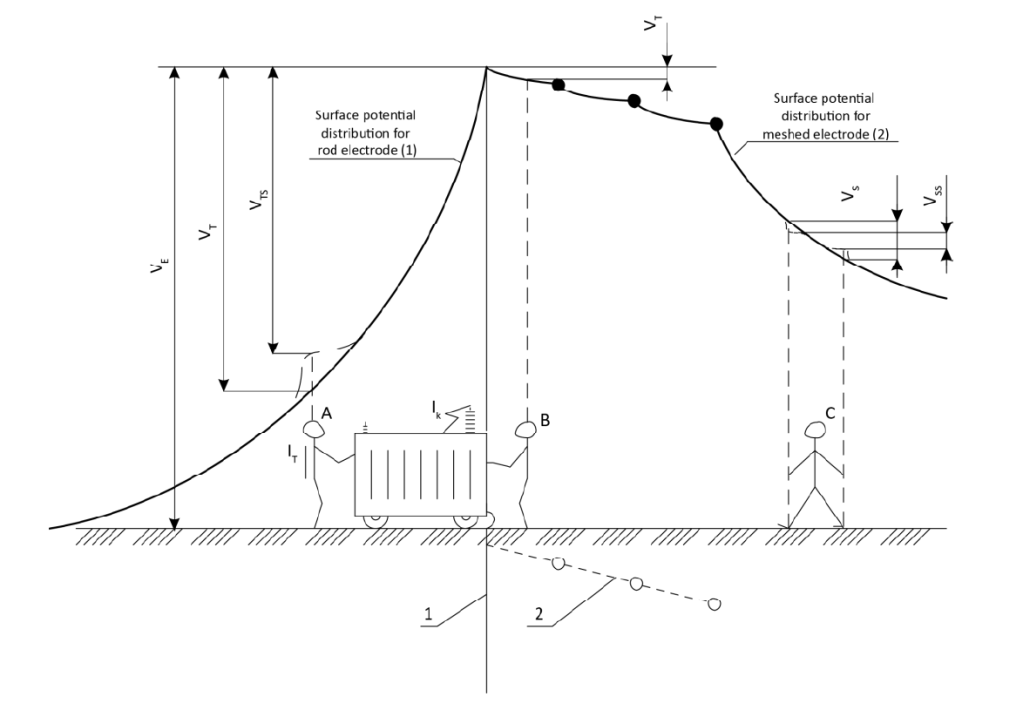
Figure 5 – Comparison of earth surface potential distribution during the current flow in the earthing system, for two earth electrode constructions:
- (1) a rod electrode LHS
- (2) a meshed electrode RHS
- VE – earthing voltage
- VT, VTS – touch voltage and shocking touch voltage respectively VS,
- VSS – step voltage and shocking step voltage respectively
- IT – shocking touch current
- IK – short circuit current equal the current flowing to the earthing system
- A, B, C – persons at various earth surface potentials
The left-hand side of Figure 5 shows the situation for a rod electrode while the right-hand side shows that for a meshed electrode. The rod electrode (1) has a low resistance but most unfavourable potential distribution while the meshed electrode (2) has a much flatter earth potential profile. The touch potential (person A) is considerably larger for the rod electrode (1) than for the meshed one (2), (person B). Step potentials (person C) are also less dangerous in case of the meshed electrode.
When a meshed earth is not possible, a ring electrode (as is common practice in Belgium and Germany, for example) provides an intermediate solution combining reasonable cost with reasonable safety.
The earthing resistance determines the value of earthing voltage, whereas the configuration of the earth electrode has significant influence on the potential distribution on the earth surface. Naturally, the configuration also influences the earthing resistance – a meshed electrode contacts a larger volume of earth – so both resistance and configuration need to be considered together. Note that, because meshed electrode systems cover large areas it is not practical to bury them deeply, so they are more susceptible to changes in soil moisture content. Improved stability of resistance can be achieved by including a number of long vertical rods in the mesh.
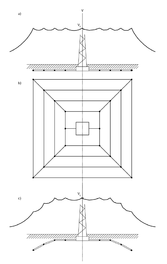
Figure 6 – The phenomenon of potential carryover. Earth surface potential distribution for two meshed earth electrodes;
a) meshed plane electrode,
b) plan of electrode;
c) electrode with two last elements placed deeper.
Meshed electrodes increase the surface area that experiences a voltage rise as the result of current flow to the earth electrode. Over the area of the mesh, equipotentiality exists, but at the periphery of the electrode there is a potential gradient as shown in Figure 6a. Although there is no touch potential – because the mesh extends beyond any metal structure by more than a meter – dangerous step voltages can occur. This situation can arise, for example, in the earthing system of a substation. In order to avoid this, the outer elements of the meshed earth electrode should be placed at a greater depth than the rest of the grid (Figure 6c).
PROPERTIES OF EARTHING AT HIGH IMPULSE CURRENTS
So far, the characteristics of earthing systems have been discussed assuming moderate current flow under steady-state conditions at the network frequency. Differences between steady-state and pulsed properties of an earthing system are caused mainly by:
- Flow of currents with very high values, up to a few hundreds of kA
- Very fast current rise times – typical lightning strikes reach a few hundred kA/µs [5]
Extremely high current density in the soil increases the electric field strength up to values which cause electrical discharges in small gaseous voids, decreasing the ground resistivity and earthing resistance. This phenomenon occurs mainly near the earth electrode, where the current density is highest, and the influence is most significant. The intensity of this phenomenon is especially high when the soil is dry or of high resistivity.
The inductance of metal parts of earth electrodes, which can be estimated as equal 1 µH/m, is usually neglected when considering earth impedance at the network frequency. However, inductance becomes an important parameter when the current slew rate is high, in the region of hundreds of kA/µs or more. During lightning strikes the inductive voltage drop (L di/dt) reaches very high values. As a result, remote parts of the earth electrode play a reduced role in conducting current to earth.
The earth resistance for pulse currents increases in comparison with its resistance for static conditions. Thus, increasing the length of earth electrodes over the, so called, critical length (Figure 7) does not cause any reduction of the earth impedance to transients.
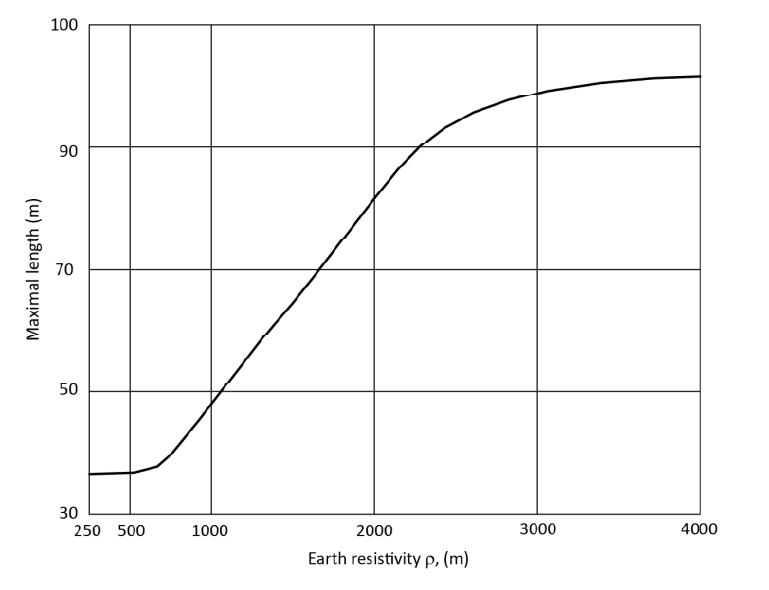
Figure 7 – Maximal length lmax of lightning earth electrodes as a function of earth resistivity ρ.
During a lightning strike both the phenomena described above have an effect, but operate in opposite directions. The high earth current decreases resistance while the high frequency increases the impedance. The overall impedance can be higher or lower depending on which effect is dominant.
CONCLUSIONS
Earthing resistance and earth surface potential distribution are the main parameters characterising the electrical properties of the earthing system.
Electrical parameters of the earthing system depend on both soil properties and earth electrode geometry. Soil properties are characterised by earth resistivity, which changes over a wide range from a few Ωm up to few thousand Ωm, depending on the type of ground and its structure, as well as its humidity. As a result, it is difficult to calculate an exact value of earthing resistance. All relationships describing earthing resistance are derived with the assumption that the ground has a homogenous structure and constant resistivity.
Ideally, the earth surface potential should be flat in the area around the earth electrode. This is important for protection against electric shock, and is characterised by touch and step voltages. Rod electrodes have the most unfavourable surface potential distribution, while meshed electrodes have a much flatter distribution.
The behaviour of the earthing system for high transient currents should be considered. Very high current values diminish earthing resistance due to the strong electric field between the earth electrode and the soil, while fast current changes increase earthing impedance due to earth electrode inductance. The earthing impedance is, in this case, a superposition of both these events.
REFERENCES
[1] IEC 61936-1 “Power installations exceeding 1 kV a.c.”, 2011-11.
[2] ABB Switchgear Manual, 10th edition, Düsseldorf, Cornelsen Verlag 1999.
[3] IEC 60364-5-54:2011 “Electrical installations of buildings – Part 5: Selection and erection of electrical equipment – Chapter 54: Earthing arrangements and protective conductors”
[4] Rudolph W., Winter O. EMV nach VDE 0100. VDE-Schriftenreihe 66. VDE-Verlag GmbH. Berlin, Offenbach, 1995.
[5] IEC 62305:2010
Application Note – Earthing Systems: Fundamentals of Calculation and Design , H. Markiewicz and A. Klajn, November 2014, ECI Publication No Cu0120, Available from www.leonardo-energy.org

Your article is very informative. To ensure the safety of people and equipment in an electrical installation, grounding must be installed. Earthing systems regulate the conductors’ relationship to the earth’s conducting surface. Earthing is therefore quite a valuable and appropriate term.
LikeLike
Thank you! I really appreciate your comment.
LikeLike