Published by E. Hering, Dresden (Germany)
Earth resistance is a key parameter in determining the efficiency of earthing systems. In this article we look at the measurement of earth resistance
1 A Few Fundamentals
1.1 Earth resistance and earth impedance
The efficiency of an earthing system is principally determined by its impedance ZE. As can be seen from figure 1, the earth impedance can be expressed as in equation (1):
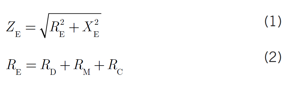
As shown in equation (2), the earth resistance RE is the sum of the dissipation resistance RD, the resistance of the metal conductor that serves as the earth electrode RM and the resistance of the earthing conductor RC, which runs between the main earthing busbar and the earth electrode. The dissipation resistance RD is the resistance between the earth electrode and the surrounding soil. The reactance of the earthing system XE can be expressed as:

with
XM reactance of the metallic earth electrode
XC reactance of the earthing conductor.
For AC supply current the reactance of the earthing conductor is only significant in the case of extended horizontal earthing strips or long earth rods. In all other cases, the difference between earth impedance and earth resistance is so small that frequently no distinction is made between these two quantities. The relevant industrial standards also treat earth impedance and earth resistance as identical.
As earthing measurements are carried out using an AC supply, it is actually the earth impedance that is measured. If the measurement frequency is greater than 50 Hz, a slightly larger earth impedance is displayed. However, overestimating the earth impedance is not a problem, as it errs on the side of safety.

Figure 1 Vector diagram of impedance in an earthing system
RD dissipation resistance; RE resistance of the earthing system (earth resistance); RM resistance of the metal conductor that acts as the earth electrode; RC resistance of the earthing conductor (e.g. connection lug, cable); XE reactance of the earthing system; XM reactance of the metal conductor that acts as the earth electrode; XC reactance of the earthing conductor; ZE earth impedance; ϕ impedance angle.
1.2 Requirements for earthing measurements
Earthing measurements are necessary whenever compliance with a specified earth resistance or a particular earth impedance is required, as is the case in the following earthing systems:
- Protective earth for TT and IT earthing systems low-voltage installations ([1], sections
411.5 and 411.6; [2]); - Joint earthing system for high-voltage protective earthing and functional earthing in transformer substations;
- Earthing system for the neutral earthing reactor of a medium-voltage distribution system.
In the case of lightning protection systems, earthing measurements must be made even when there is no requirement to comply with a specific value. The results of repeat tests must be compared with those of earlier measurements.
1.3 Standards for measuring instruments
The standards contain the requirements that have to be met by the manufacturers of measuring equipment. For users, these standards serve only informational purposes.
In low-voltage systems earthing measurements must be made using equipment that complies with the VDE 0413 standards (VDE: Verband der Elektrotechnik Elektronik Informationstechnik e.V./ engl.: Association for Electrical, Electronic & Information Technologies) (see [3], sec. 61.1). All equipment must comply with the specifications in IEC 61557-1:2007 [4]. In addition, equipment must also comply with the following standards depending on the type of device or measuring method for which it is used:
- IEC 61557-5:2007 Equipment for measuring resistance to earth [5]
- IEC 61557-6:2007 Equipment for testing, measuring or monitoring protective measures involving residual current devices [6]
- IEC 61557-10:2007 Combined measuring equipment [7].
Equipment manufactured in accordance with earlier editions of the VDE 0413 series of standards can of course also be used.
1.4 Selecting the right measuring equipment
It is not enough for users to simply follow the (frequently unclear) instructions provided by the manufacturer, they need to be aware of and understand the measuring method they want to apply. Measuring instruments that do not make it clear which measuring method is being applied should not be used.
Before purchasing equipment, users should request technical descriptions of the devices of interest as well as their performance data and, if possible, instruction manuals, and should assess the equipment on the basis of this documentation.
1.5 Avoiding hazards and measuring errors
The process of measurement and any accompanying procedures (e.g. breaking standard connections and making non-standard connections) must not pose a safety hazard ([3], sec. 61.1.3). The magnitude of the test voltage or the test current must be limited (see sections 3.1 and 4.1). Before breaking a connection that is required for electric shock prevention, the entire power installation must be disconnected from the supply and locked out to prevent it being switched on again.
Any measurement that involves breaking connections (e.g. opening the inspection joint of a lightning protection system) must never be carried out during a storm or whenever a storm could be expected. Failure to comply could be hazardous, particularly for the person performing the operation. After the measurement has been completed, any connections that were broken must be properly restored.
If the test current is split so that part of it runs parallel to the earth electrode being measured, the earth resistance displayed by the meter will be too small. The person conducting the measurement must therefore be aware of everything that is connected to the earth electrode under test [8]. Measurements must only be carried out by competent persons.
1.6 Taking the effects of weather into account
The specific resistance of soil decreases with increasing temperature and increasing soil moisture levels. Whereas these effects are of minor consequence for foundation earth electrodes in buildings with a basement or for long (vertical) rod electrodes, they have to be taken into account in the case of horizontal surface earth electrodes.
Measurements made during cold, dry weather remain unaffected, but measurement data recorded in warm weather or after a rain shower have to be adjusted upward.
1.7 Assessing measurement results
Earth resistance meters are not error free. Measurement errors can occur even if the conditions specified in the relevant standards and instrument instruction manuals are complied with and even in the absence of interference effects. The magnitude of an instrument’s operating error is listed on its technical specification sheet or in its instruction manual. In those methods of measuring earth resistance that draw current directly from the power source (see sections 2.4 and 4), additional measurement uncertainty can be caused by random current and voltage fluctuations in the supply during the measurement.
Examples of possible operator errors include:
- failure to take account of connections detrimental to the measurement process
- connecting the instrument leads incorrectly or selecting the wrong setting on the selector switch of the instrument
- inserting the auxiliary earth electrode or probe in the wrong location
- meter reading errors
- failure to implement measures to reduce systematic measurement errors.
Results from first-time measurements should be compared with the project specifications, results of repeat tests should be compared with those of earlier measurements. If significant differences are apparent, the possible causes of the discrepancy should be determined. The influence of weather on the measurement results and how this can be taken into account is discussed in section 1.6.
1.8 Test report
Measuring earth resistance is only one of several tests that have to be performed on earthing systems [9]. In general, the results from all the tests are contained in a single test report. The measurements performed and any accompanying action that is taken must be described precisely so that they can be reproduced at a later date. Information that must be provided includes:
- the measurement method used
- the type of measuring instrument used
- the positions of any selector switches, if relevant
- details of any connections that were broken or made for the purposes of the measurement.
The results of the measurement must be stated clearly and unambiguously. This also applies to any weather-related adjustments of the results that may have been made.
The test report is required by
- [3], section 61.1.6 concerning earthing systems in low-voltage networks
- [10], annex E, section E.7.2.5 concerning lightning protection systems
- both standards apply if the earthing system serves both purposes.
2 Overview of Measurement Methods for RE
2.1 Principles
There is a wide degree of variation in the internal circuitry of the measuring instruments used and the layout and arrangement of the external measuring circuits. However, a common feature of all the methods is that they determine the earth impedance by measuring the voltage across the earthing system for a known test current. Leads that carry the test current outside of the instrument are shown in red in the diagrams.
Known measurement methods are listed in table 1. The underlying circuit principles are shown in figures 2 to 4. The unusually long names given here to the various methods ensure that the methods can be distinguished unambiguously.
Although there are clear differences between the individual measurement methods, no one particular method can be said to be ideal. Each method has its own particular disadvantages such as limited applicability, electric shock hazard, larger measurement errors or requiring greater time and effort to complete. The various advantages and disadvantages of the individual measurement techniques are described in more detail in sections 3 and 4. All of the methods discussed must only be carried out by competent persons exercising due care and attention. In those methods that do not draw current directly from the supply (columns 1 to 6 in table 1), the measurement frequency used
will be at least 5 Hz above or below the frequencies 16.7 Hz, 50 Hz and integer multiples thereof. This prevents interference from supply frequency currents (‘interference currents’) that can falsify measurement results.
In those methods that do draw current directly from the supply (columns 7 to 9 in table 1), it is of course essential that the supply frequency and measuring frequency are identical. This means that the interference effects mentioned above cannot be ruled out when such methods are used. However, these methods are simpler to perform and offer advantages in terms of their applicability.

Table 1 Overview of earth resistance measuring methods
2.2 The balanced-bridge method
The balanced-bridge method as described by Behrend is one of the techniques for measuring earth resistance that does not involve drawing current directly from supply. Earth resistance meters based on this method are no longer manufactured, as other more user-friendly instruments have now been developed for the same sorts of applications. These new meters use the so-called current-voltage method, which also does not involve current being drawn from the supply. Nevertheless the balanced-bridge method is described here because it is of fundamental importance to the development of earth resistance measurement techniques and because meters based on this method are still in use.
The measurement circuit for the balanced-bridge method is shown in figure 2. The method involves driving an auxiliary earth electrode1) and a probe2) temporarily into the soil. When the earth meter is in its balanced state, there is no current flowing in the probe. The resistance to earth of the probe has therefore no influence on the measurement result; it simply lowers measurement sensitivity. Information on the alignment and separation of the auxiliary earth electrode and the probe is provided in section 3.
The AC power source PSAC is located between the connection point for the earth electrode under test (socket E) and that for the auxiliary earth electrode (socket H). The AC source is connected in series with the primary winding of a current transformer CT. Connected to the secondary winding of the current transformer is a variable voltage divider. The setting chosen for the left part of the divider R2 (‘reference resistance’) is displayed on the scale on the voltage divider’s control unit. A null detector N with a rectifier REC in series is located between the variable tap point of the voltage divider and the connection point for the probe (socket S). The rectifier is driven by the AC power source. A capacitor C prevents any DC current from flowing across the probe. One end of the voltage divider is connected to the earth electrode being measured via the instrument sockets ES and E. The transformation ratio tr of the current transformer can be switched to achieve the required measurement range.
When balanced, the current I3 in the probe is zero. The same current I1 therefore flows in the auxiliary earth electrode and in the earth electrode under test. Additionally, the voltages U2 (‘reference voltage’) and U1 are of the same size. The voltage U1 corresponds to the earth electrode voltage that drives the test current I1 in the earth resistance RE of the test object E, whereas U2 is the voltage drop that maintains the current I2 (‘reference current’) in the reference resistor R2. The potential drops obey Ohm’s law as expressed by the equations U1=I1 · RE and U2=I2 · R2. If the transformation ratio of the current transformer tr = 1:1, then I2 = I1 and the value of the earth resistance RE is equal to the selected reference resistance R2. The earth resistance can therefore be read off the voltage divider scale mentioned above. If another transformation ratio is used, this must be multiplied by the value of the reference resistance R2, i. e. RE=tr ·R2.
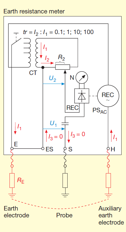
Figure 2: The balanced-bridge method
REC rectifier; I1 test (or measuring) current; I2 Reference current; I3 current whose magnitude is zero when bridge is balanced; C capacitor; N null detector; RE earth resistance being measured; R2 reference resistance; CT current transformer; U1 Voltage
across earth electrode under test; U2 reference voltage; tr transformation ratio of the CT; PSAC AC power supply.
2.3 Other measurement methods without supply current
Another group of methods for measuring earth resistance that do not draw current directly from the supply are the so-called current-voltage techniques illustrated in figure 3. The earth resistance RE is determined from the voltage UM that appears across the earth electrode and across the sockets ES and S, and the measured current I.
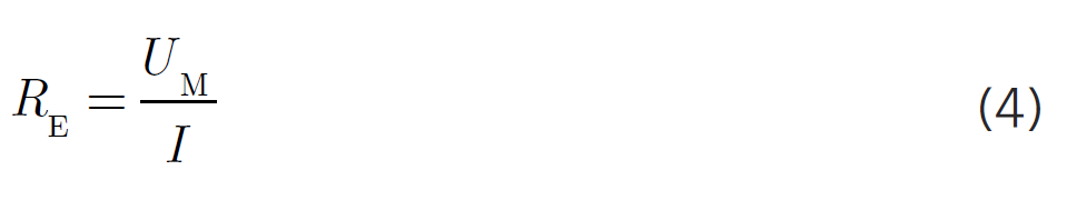
Figure 3 simply illustrates the principle of the measurement and shows only a small part of the complex circuitry within the earth resistance meter. Usually, the voltage UM and current I are not shown separately and the meter only displays a digital reading of the earth resistance RE. If the AC supply source PSAC is a constant-current generator, the earth resistance can be displayed directly on the voltage meter. When the balanced-bridge method was first developed, the only exterior circuit known was that shown in figures 2 and 3a). It was therefore usual to consider the circuitry inside the meter and the exterior circuit as a single entity. However, as indicated in columns 2 and 3 in table 1, the same meter can be used for measurements with the exterior circuits shown in figures 3b) and 3c). Equally, the earth resistance meters used for the current-voltage methods that do not draw current directly from the supply can be used like the meters designed with the balanced-bridge circuit. The internal circuits can therefore be freely combined with the exterior circuits.

Figure 3 Current-voltage methods that do not draw current directly from the power supply
- a) with probe and auxiliary electrode;
- b) with probe, but without an auxiliary electrode;
- c) no probe, no auxiliary electrode (measures resistance of conductor loop via earth return path). I test current; Rloop loop resistance; UM test voltage.

Figure 4 Current-voltage methods that draw current directly from the power supply
- a) with probe;
- b) using PEN conductor or neutral conductor instead of probe;
- c) no probe (measures resistance of conductor loop via earth return path); U0 conductor-to-earth voltage
2.4 Measurement methods with current from the supply
These methods can only be used in networks with a direct connection to earth. As shown in figure 4, the measurement involves drawing the test current from the phase conductor of the supply system. The meters used in this type of measurement are primarily designed for testing electrical safety systems involving residual current devices. The meters are generally connected to the supply via a flexible power lead and an earthed safety plug.
3 Current-Voltage Method that Draws No Supply Current
3.1 Earth resistance meters
The four connection sockets are labelled as shown in figure 5. Sockets for the supply current path and for current measurement:
- E – Earth electrode (test object)
- H – Auxiliary earth electrode1) Sockets for the voltage measurement path:
- ES – Earth electrode (or the probe located close to the earth electrode when measuring the soil resistivity)
- S – Probe2) Normally when measuring the resistance to earth, the sockets E and ES are connected to one another via a removable link or via a contact strip within the meter’s selector switch as this ensures that the earth electrode under test is connected to both the current and voltage measurement paths. If, in addition, a jumper is placed between sockets H and S, the earth resistance meter can be used as a simple ohmmeter.
The frequency of the AC supply PSAC is at least 5 Hz above or below the frequencies 16.7 Hz and 50 Hz and any integer multiples thereof. Typically, the supply frequency is in the range 41–140 Hz, though in some meters a higher frequency is used. Some earth resistance meters also offer the option of selecting the frequency. A number of meters with automatic frequency control (AFC) automatically switch to that frequency offering the lowest level of interference.
To protect against electric shocks, the open-circuit test voltage generated by the meter must not exceed 50 V (r.m.s.) and 70 V (peak). In the case of earth resistance meters used on agricultural sites, these values must be halved. Alternatively, the short-circuit current must not exceed 3.5 mA r.m.s. and a peak value of 5 mA (see [5], sec. 4.5). If neither of these conditions are met, the meter must switch off automatically.
The meter is powered either by a battery, a group of primary cells or a hand-driven generator, though the latter method is now rare. The meter must indicate whether the end-point voltage of the power supply is sufficient to maintain proper instrument function (see [4], sec. 4.3).
When earth resistance is measured by a method that does not involve current being drawn directly from the supply, the earth resistance RE is computed as the quotient of the measured voltage UM that appears across the earth electrode (and across the meter sockets ES and S) and the measured current I (that flows through sockets E and H). Figure 5 only indicates the basic principle of the complex circuitry within the meter. Usually, the voltage UM and current I are not shown separately and the meter only displays a digital reading of the earth resistance RE. If the AC supply source is a constant-current generator, there is no need to measure the current and calculate the quotient. In this case a voltage meter can be calibrated to display the earth resistance directly.
Most meters are equipped with a switch for selecting the type of measuring circuit, the measurement frequency and/or the measurement range, and for switching the power on and off. Most meters also have a button that is used to initiate measurement. The earth resistance meter must also indicate that the resistance of the auxiliary earth electrode and the probe are within the specified limits (see [5], sec. 4.4). However, it is not advisable to rely too heavily on a warning signal, because by the time a warning signal has been issued, the limit may have been exceeded by a significant amount. User-friendly devices offer additional functions such as:
- warning signal or automatic cut-out if too great an interference voltage is detected
- warning signal or disabling of measurement function if test current is too small
- display of test current (for monitoring purposes only when measurements made with a constant-current generator)
- automatic measurement range selection
- display hold function
- data storage for transmitting or printing measurement results.
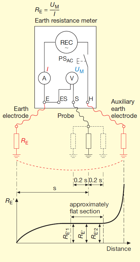
Figure 5 Current-voltage methods that do not draw current directly from the power supply and that use a probe and an auxiliary earth electrode
I test current; RE earth resistance being measured; RE´ measured earth resistance; UM test voltage
3.2 Methods Using a Probe and An Auxiliary Earth Electrode
3.2.1 Principle
As shown in figure OE, the earth electrode under test, an auxiliary earth electrode and the probe are connected to the earth resistance meter. The test current I flows through the earth electrode, the soil and the auxiliary earth electrode. The voltage UM that appears across the earth resistance RE also appears across the meter sockets ES and S. The earth resistance is displayed as the value of UM divided by I.
3.2.2 Earth electrode (test object)
If socket E is connected to the beginning of the earthing conductor (at the main earthing terminal), the earthing conductor will be included in the measurement of the earth resistance. If, on the other hand, socket E is connected directly to the earth electrode, the resistance of the earthing conductor will not be included in the measurement. The difference, however, is usually slight.
The resistance of the measuring leads will be included in the measurement. This will result in an overestimation of the earth resistance and thus yield a value that errs on the side of safety. To reduce the magnitude of the error, it is expedient to position the earth resistance meter close to the point of connection and to use a short measuring lead. The resistance of the measuring lead can of course be measured and this value subtracted from the value displayed by the earth resistance meter. If the effect of the measuring lead’s resistance is to be avoided at all costs, the jumper linking sockets E and the ES must be removed and each socket connected to the earthing system by its own measuring lead.
The earth electrode under test must not be connected to any other earth electrodes as this would falsify the result of the measurement. In the TN earthing systems found in consumer installations, the earthing conductor must be disconnected from the main earthing busbar as the latter is connected to the PEN conductor of the supply network. This is not required in TT systems as the main earthing busbar is not connected to the neutral conductor of the power supply network. If, nevertheless, the earthing conductor is disconnected, the entire system must be de-energized beforehand and locked out to prevent it being switched on again.
3.2.3 Auxiliary electrode1)
The auxiliary earth electrode should be positioned as far away as possible from the earth electrode under test, so as to minimize the degree of overlap between the potential gradient areas (‘spheres of influence’) surrounding the two electrodes. The larger the electrodes, the farther apart they must be. As a rough guide, the minimum distance apart can be taken to be three times the depth of a rod earth electrode or the average diameter of a ring earth electrode. The figure of 40 m that is found in the documentation provided by some manufacturers can only be considered to be a rough average value. Whether the chosen distance is appropriate will be shown when the correct alignment and positioning of the electrodes is carried out (see sec. 3.2.4).
The greater the resistivity of the soil, the longer the auxiliary electrode needs to be and the deeper it needs to be driven into the ground. If the resistance of the auxiliary earth electrode is too large, measurement errors can arise, because, for example, the constant current normally generated by the AC supply cannot then flow. In such cases, it can prove useful to saturate the area of ground being used for the measurement with water.
3.2.4 Probe2)
As the internal resistance of the voltage measurement path is very large, the resistance of the probe and therefore the size of the probe is of minor importance. The preferred location of the probe is on the straight line between the earth electrode and the auxiliary earth electrode at a position where it has minimum interaction with the spheres of influence of the two electrodes (see diagram in figure 5).
If one were to carry out a series of measurements with different distances between the earth electrode and the probe the results would form a curve whose ends are relatively steep while the intermediate section of the curve is flatter. If the distance between the earth electrode and the auxiliary electrode is large enough, the curve will have an approximately horizontal central section in which the measured resistance to earth is essentially independent of electrode separation.
This central section must be determined by at least three measurements. The midpoint of the central section is not midway between the earth electrode and the auxiliary earth electrode, but lies closer to the auxiliary earth electrode as the spatial extent of the spheres of influence associated with the two earth electrodes differ. In general, the optimum separation between the earth electrode and the probe is about two thirds of the distance between the earth electrode and the auxiliary earth electrode3).
3.2.5 Limitations of method
If no portion of the resistance vs. distance curve is approximately horizontal, then the distance between the earth electrode under test and the auxiliary earth electrode is too small. If the curve exhibits an unusual profile, buried metal installations (e. g. water pipes) are very probably influencing the measurement. In such conditions it is not possible to achieve usable results from the measurement. Measurement may be possible if the electrodes can be laid out perpendicular to their original direction or perpendicular to the longitudinal axis of the buried metal installation or so that they run away from and not above the buried metal installation.
It is also not possible to achieve reliable results if the earth electrode under test is surrounded by other earth electrodes, for example in areas with a high density of buildings. Furthermore measurement is impossible whenever the auxiliary earth electrode and the probe cannot be positioned in the right locations. In all such cases, another measurement technique must be selected.
1) In some publications the auxiliary electrode is also referred to as the outer test electrode, or current test stake.
2) In some publications the probe is also referred to as the inner test electrode, or voltage test stake.
3) Some manufacturers state that the distance between the earth electrode and the probe should be half the distance between the earth electrode and the auxiliary earth electrode. That is incorrect. Other companies recommend placing the probe at a distance from the earth electrode that is always 62 % of the separation between the earth and the auxiliary earth electrode. This method is thus sometimes referred to as the 62 % method. The 62 % mark generally gives a good approximation of the correct location. But the optimum position must always be determined by moving the probe to neighbouring positions.
3.3 Method Using a Probe But No Auxiliary Earth Electrode
3.3.1 Principle
As shown in figure 6, the functional earth of the supply network acts as a replacement for the auxiliary earth electrode. It is extremely important to ensure that the connection is not accidentally made to one of the phase conductors.
In a TN system, the H socket of the meter has to be connected (for instance, via the earthing contact of a plug) to the protective earth (PE) conductor, which itself has been branched off the PEN conductor. The meter socket E is connected to the earthing conductor, which has to be disconnected from the main earthing busbar. Supply networks configured with the TT earthing system have a neutral conductor instead of the PEN conductor. This has to be treated as a live conductor even though it is connected to a functional earth. Applying this method of measuring earth resistance to a TT system would therefore involve connecting the earth resistance meter to the neutral conductor. The method is therefore not approved for use with TT systems.

Figure 6 Current-voltage methods that do not draw current directly from the power supply and that use a probe but no auxiliary earth electrode
EC earthing conductor; MEB main earthing busbar; RB resistance to earth of the functional earth electrode
3.3.2 Problems in the TN system
The method does not function in a TN system if the electrode being measured is strongly coupled or if it is connected via a metal conductor to another earth electrode that itself is connected to the PEN conductor. This would result in the test current flowing in the wrong path so that the display on the earth resistance meter would be smaller than the true value of the resistance to earth. This is discussed in more detail in section 3.4.2.
3.4 Method Without a Probe and an Auxiliary Earth Electrode (‘Stakeless Method’)
3.4.1 Principle
This method (illustrated in figure 7) is an earth-loop resistance measurement because it involves measuring the resistance of a conductor loop via an earth return path. The S and H sockets of the earth resistance meter are connected together. The advantage of this method is that neither an auxiliary earth electrode nor a probe need to be used.
In a TN system the earthing conductor (EC) is disconnected from the main earthing busbar (MEB) and the earth resistance meter is inserted between them. This method is not suitable for measurements on a consumer installations with a TT earthing system.
The resistance measurement displayed on the meter includes the resistance to earth of the functional earth and the resistance of the PEN conductor. If they were accurately known, these values could be subtracted from the resistance displayed on the meter. However, they are difficult to determine, because the functional earth in a TN system comprises not only the functional earth electrode shown in figure 7, it is also connected to numerous earths in the consumer installations of neighbouring buildings. The error that is introduced by measuring these additional resistances results in an overestimation of the earth resistance, yielding a value that errs on the side of safety.
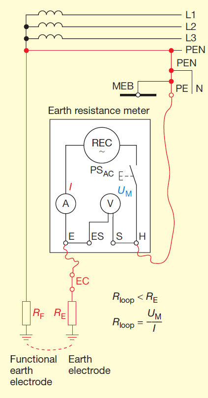
Figure 7 Current-voltage methods that do not draw current directly from the power supply and that use neither a probe nor an auxiliary earth electrode (resistance of conductor loop via earth return path) Rloop loop resistance.
3.4.2 Problems in TN systems
The problem mentioned earlier in section 3.3.2 can also arise when measuring earth resistance without an auxiliary earth electrode and without a probe. Some examples of configurations where problems can arise are shown in figure 8.
Temporary remedial measures include:
- Disconnecting the metal connection between the earth electrodes as shown in figure 8b).
- Disconnecting the second earth electrode from the PEN conductor, if permitted by the owner. The residual influence of the second earth electrode on the earth resistance measurement is not a disadvantage, as it acts to improve the performance of the first earth electrode. More details can be found in reference [8].
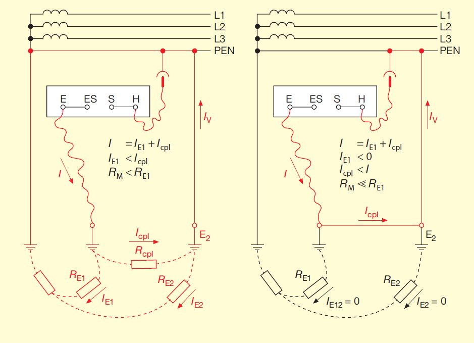
Figure 8 Cases involving a TN system in which the method shown in fig. 7 is not suitable
- a) Small distance and therefore small coupling resistance Rcpl between the earth electrode under test E1 and a second earth electrode E2 that is connected to the PEN conductor.
- b) Metallic connection to a second earth electrode that is itself connected to the PEN conductor. Icpl current causing measurement error; RE1 earth resistance being measured; RM earth resistance displayed on meter.
3.5 Stakeless methods (no probe, no auxiliary earth electrode) using a clamp-on ohmmeter
This is a variation on the measurement method described in section 3.4. This technique differs from that shown in figure 7 in that instead of inserting an earth resistance meter into the earthing conductor, a clamp-on ohmmeter (COM) is placed around the earthing conductor (see figure 9). The clamp-on ohmmeter contains both a current-to-voltage transformer (a voltage inducing clamp, VIC) and a current transformer (a current measuring clamp CMC).
Models available include:
- Chauvin Arnoux Earth Clamps C.A 6410, C.A 6412 or C.A 64154);
- Fluke Earth Ground Clamp Meter 16305).
The meter displays the resistance calculated as the quotient of the voltage induced by the VIC in the earthing conductor and the resulting test current registered by the CMC. In this case the resistance is the loop resistance Rloop, or more precisely the loop impedance (see section 3.4.1).
Another solution (no separate diagram provided) involves clamping two split-core current transformers around the earthing conductor, one of which functions like the voltage-inducing clamp VIC while the other corresponds to the current measuring clamp CMC that measures the test current. The clamps are connected to a special earth resistance meter (Fluke Earth Ground Tester 1623 or 1625). Depending on which of the Fluke meters is used, either EI-1623 or EI-1625 ‘selective/stakeless clamp set’ is required. The advantage in both cases is that the earthing conductor does not need to be disconnected, making measurement safer and quicker. The problem discussed in section 3.4.2 can also arise in these cases.
If this method is used to make measurements on consumer installations, they must be designed with a TN earthing system. The method is suitable for measuring the resistance to earth of a pylon in an overhead power transmission line if the clamps can be fitted around the earthing conductor.
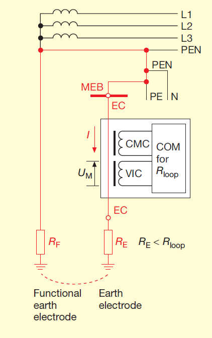
Figure 9 Method as in figure – but with a clamp-on ohmmeter rather than an earth resistance meter
EC earthing conductor; VIC voltage-inducing clamp; CMC current measuring clamp; COM clamp-on ohmmeter.
3.6 Selective earth resistance measurements using a probe, an auxiliary earth electrode and a clamp-on ohmmeter
The earth resistance measurement described in this section6) is used if the earth electrode under test cannot or should not be disconnected from other earth electrodes to which it is wired in parallel. This method is based on the technique using a probe and auxiliary earth electrode that is discussed in section 3.2, but in this variant (see figure 10a) a special earth resistance meter (Fluke 1623 or 1625) and an additional clamp-on current transformer (CMC) are required. The current measuring clamp CMC is clamped around the earthing conductor EC connected to the earth electrode under test and connected to a multi-pole socket on the earth resistance meter. When the meter is connected in this way and the rotary selector switch has been set appropriately, IP, the portion of the test current I flowing via the other parallel earth electrodes, has no effect on measurement result so that the branch current IE recorded by current measuring clamp CMC is solely responsible for determining the resistance to earth RE displayed by the meter.
Figure 10b) shows the measurement circuit used when dealing with a steel-lattice electricity pylon that cannot be electrically disconnected from the earthed conductor (e. g. counterpoise, PEN conductor or neutral conductor). As the pylon structure serves as the earthing conductor EC, it is clearly not possible to clamp a CMC around the earthing conductor as in figure 10a). In this case, measurements are made by consecutively clamping a splitcore transformer SCT (Fluke EI-162BN7)) around the four pylon legs that are connected to the four pylon stubs that act as earth electrodes. The earth resistance meter displays the resistances RE1 to RE4 consecutively. The resulting earth resistance RE of the four mast feet, which are connected to one another through the steel lattice structure, can be calculated by equation (5):

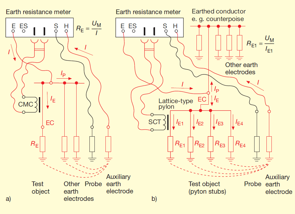
Figure 10 Selective earth resistance measurements using a probe, an auxiliary earth
electrode and split-core current transformers
- a) Test object whose earthing conductor can be clamped by a split-core current transformer;
- b) Pylon whose legs can be clamped by a split-core current transformer near the foundation of the pylon IE part of test current flowing through the earth electrode under test to the auxiliary earth electrode; IE1 to IE4 parts of IE flowing in the pylon legs and stubs; IP portion of the test current flowing to the auxiliary earth electrode via the other parallel earth electrodes (current path through soil not shown in part b) of figure).
4) Induced voltage: approx. 60 mV; frequency: 2403 Hz; inner diameter of clamp jaw: 32 mm. Data provided without warranty.
5) Induced voltage: approx. 30 mV; frequency: 1667 Hz; inner diameter of clamp jaw: 23 mm. Data provided without warranty.
6) On its own, the expression ‘selective earth measurement’ is ambiguous, as other earth resistance measurement techniques are also selective, e.g. those presented in sections 3.4, 3.5 and 4.6.
4 Measurement Methods That Draw Current From Supply
4.1 Measuring equipment
The meters used for this type of measurement are designed primarily for testing electrical safety systems that make use of residual current devices. To ensure the simplest and safest connection to the power supply, the meters are typically equipped with a flexible power cable and an earthed safety plug. The meters also have a socket S for the probe (see figures 11 and 13). The socket E is used to connect the meter to the earth electrode under test unless one of the cores (protective earth core) of the flexible power cable and the earth contacts on the plug are used for this purpose. As the test meters are classified as Class II equipment (see ref. [4], sec. 4.5), the core and the plug’s earth contact do not serve as protection against shock hazards.
The meters do not have their own power source unless this is needed for some other type of measurement. Some meters may have an additional connector socket for a current measuring clamp.
7) The jaws of the split-core transformer are dimensioned for large rectangular-section conductors such as the legs of high-voltage pylon
Figures 11 to 14 show the basic principles of the complicated circuitry inside these meters. In most of these meters, the actual measurement process (including any gradual increase in the test current that may be involved) is carried out automatically. Rather than displaying the measured voltage and current separately, the resistance to earth is computed and displayed digitally on the meter.
A selector switch enables the type of measurement, measurement technique, measurement circuit, parameter range and/or measurement sequence to be chosen. Most meters are fitted with a ‘START’ button to initiate the measurement process. User-friendly devices offer additional functions such as:
- Multiple measurements with display of average result
- Smoothing function
- Display hold function
- Data storage for transmitting or printing measurement results.
To provide protection against electric shock, the meter must switch off automatically as soon as it causes a fault voltage greater than 50 V in the earthing system being measured. If a variable resistor is used to increase the test current, the current must not exceed 3.5 mA at the beginning of the measurement (see ref. [6], sec. 4.7). Measurements in which the test current is increased gradually and measurements in which the current is only allowed to flow at maximum strength for a short period are both common.
The difficulty associated with drawing current directly from the power supply is that the measurement is made at the supply frequency and interference currents that originate in the power supply or that are carried via earth can easily introduce measurement errors. The larger the test current, the less effect these sources of interference will have. It is therefore expedient to work with a large test current. However, a large test current can itself be problematic when the meter is connected behind a residual current device, as it can cause the RCD to trigger. This can be avoided by using one of the following procedures:
- Ensuring that the magnitude of the test current is only half that of the rated residual current IΔN of the RCD.
- Connecting the meter in front of the RCD or to a circuit that is not equipped with an RCD.
- According to the manufacturer Chauvin Arnoux the patented ‘ALT system’ used in its C.A 6115 N and C.A 6456 Earth Clamps enables these devices to make earth resistance measurements using a larger test current even if connected behind a 30 mA RCD.
Whenever interference effects may play a role, several measurements should be conducted and the results compared with one another.
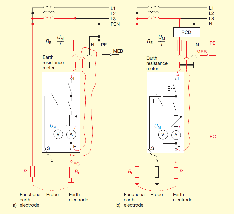
Figure 11 Current-voltage methods that draw current directly from the power supply and
that use a probe
- a) Installation with TN system;
- b) Installation with TT system EC earthing conductor; RCD residual current device; I test current; MEB Main earthing busbar; RF resistance of functional earth; RE earth resistance being measured; UM test voltage

Figure 12 Current-voltage methods that draw current directly from the power supply and
that use the PEN or neutral conductor instead of a probe
- a) Installation with TN system;
- b) Installation with TT system
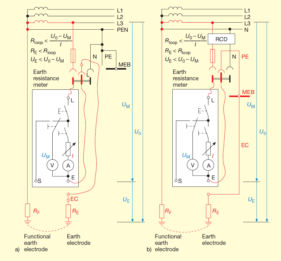
Figure 13 Current-voltage methods that draw current directly from the power supply and
that do not use a probe
- a) Installation with TN system;
- b) Installation with TT system
Rloop loop resistance; U0 conductor-to-earth voltage; UE voltage across tested earth electrode

Figure 14 Selective earth resistance measurement methods that draw current directly from
the power supply and that use a probe and a clamp-on ammeter
- a) Installation with TN system;
- b) Installation with TT system IE portion of test current flowing to the earth electrode under test; IF portion of test current flowing to the other earth electrodes; CMC current measuring clamp
4.2 Connections to power supply and earth electrode
The meter is typically connected to the power supply via its earthed safety plug. If the plug is inserted incorrectly, no hazard arises but no measurement is possible. Although not shown in the figures, the internal circuitry of most of the meters only functions if the meter is connected to the phase conductor and to the neutral conductor.
The test current can induce accidental triggering of an upstream RCD. This may need to be taken into account when connecting the meter (see discussion in section 4.1 above). Depending on the type of meter used, the earth electrode to be measured is
- either connected directly to socket E of the meter (see fig. 4 in section 2)
- or (in most cases) is connected to the meter via the plug’s earth contact as shown in figures 11 to 14.
Connections between the earth electrode under test and other earth electrodes would yield erroneous results. It is for this reason that when measurements are made on consumer installations with a TN earthing system, the earthing conductor EC has to be separated from the main earthing busbar MEB (see figures 11a) to 14a)) as the latter is connected via the PEN conductor of the service cable and the supply network to other earth electrodes. Disconnection is not required in a TT system as the main earthing busbar is not linked to the neutral line of the supply network and the connection can be made as shown in figures 11b) to 14b).
4.3 Methods using a probe
This method is the most accurate of the techniques that draw current directly from the supply provided that the probe can be inserted into the soil at a suitable location. A schematic of the measurement set-up is shown in figure 11. The probe has to be located so that it is outside the sphere of influence of the earth electrode. The voltage UM between the sockets E and S generates the test current I in the earth electrode.
4.4 Method using the PEN conductor or neutral conductor instead of a probe
This measuring techniques can be used whenever it is not possible to insert a probe into the ground at the right location. In this method (see figure 12 ) the probe is replaced by connecting socket S of the meter to the PEN or PE conductor in a TN system or to the neutral conductor in a TT system. Caution! The neutral conductor must be treated as if it is live, even though it is earthed.
The value displayed by the meter includes the resistance to earth of the functional earth electrode. This will overestimate the resistance of the earth electrode and thus yield a value that errs on the side of safety.
The voltages generated by operating currents and by fault currents in the functional earth or in the PEN conductor or neutral conductor of the power supply system can result in erroneous measurement results. The accuracy of this technique is therefore lower than that achievable using the method described in section 4.3.
4.5 Method without a probe
This method (illustrated schematically in figure 11) involves measuring the resistance of a conductor loop via an earth return path. In this method, the voltage across the test object (UE) is not measured directly. It is determined as the difference between the potential drop between the phase conductor and earth when the test resistance is switched off (U0) and that when the test current I is flowing (UM). The resistance value measured includes the resistances of the functional earth, the transformer and the phase conductor. This will result in an overestimation of the earth resistance and thus yield a value that errs on the side of safety.
This method is particularly attractive as it can be performed with a minimum of effort. But it suffers from the weakness that supply load fluctuations that happen to occur simultaneously while the measurement is being made will cause significant additional measurement errors. To limit these errors, it is therefore expedient to work with a large test current. It is also advisable to perform numerous measurements, to reject any extreme values recorded and to compute the mean value from the remaining measurement data.
4.6 Selective earth resistance measurements using a probe and a clamp-on ammeter
The method selective earth resistance measurement8) is used if, for the purposes of the measurement, the earth electrode under test cannot or should not be disconnected from other earth electrodes to which it is wired in parallel. It is based on the method using a probe discussed in section 4.3, but in this variant (see figure 14) a special earth resistance meter (Chauvin Arnoux C.A. 6115N or C.A. 6456) and an additional current measuring clamp CMC are required. The current measuring clamp is connected to a multipole socket on the meter and the clamp jaws are placed around the earthing conductor EC connected to the earth electrode under test.
If the meter is connected in this way and if the rotary selector switch set appropriately, IP, the portion of the measuring current I flowing via the other parallel earth electrodes, has no effect on measurement result so that the branch current IE recorded by the current measuring clamp CMC is solely responsible for determining the resistance to earth RE displayed by the meter.
8) On its own, the expression ‘selective earth measurement’ is ambiguous, as other earth resistance measurement techniques are also selective, e. g. those presented in sections 3.4, 3.5 and 3.6.
References
[1] IEC 60364-4-41:205 Erection of power installations with nominal voltages up to 1000 V – Part 4-41: Protection for safety – Protection against electric shock.
[2] Hering, E.: Schutzerder des TT-Systems (engl.: Protective earthing in the TT system). Elektropraktiker, Berlin 59 (2005) 5, p. 370-373.
[3] IEC 60364-6:2006-02 Low-voltage electrical installations – Part 6: Verification.
[4] IEC 61557-1:2007 Equipment for testing, measuring or monitoring of protective measures – Part 1: General requirements.
[5] IEC 61557-5:2007 Equipment for testing, measuring or monitoring of protective measures – Part 5: Resistance to earth.
[6] IEC 61557-6:2007 Equipment for testing, measuring or monitoring of protective measures – Part 6: Effectiveness of residual current devices (RCD) in TT, TN and IT systems.
[7] IEC 61557-10:2000 Equipment for testing, measuring or monitoring of protective measures – Part 10: Combined measuring equipment for testing, measuring or monitoring of protective measures.
[8] Hering, E.: Probleme mit einem der Erdungsmeßverfahren beim TN-System (engl.: Problems with an earth resistance measurement technique in a TN system). Elektropraktiker, Berlin 53 (1999) 9, p. 820-822.
[9] Hering, E.: Durchgangsprüfungen an Erdungsanlagen [Continuity testing in earthing systems]. Elektropraktiker, Berlin 59 (2005) 11, p. 888- 891 und in diesem Sonderdruck.
[10]DIN EN 62305-3 (VDE 0185-305-3):2006-10: Protection against lightning – Part 3: Physical damage to structures and life hazard.
