Published by Andrzej FIRLIT, Bogusław ŚWIĄTEK, Zbigniew HANZELKA, Krzysztof PIĄTEK, Mateusz DUTKA, Tomasz SIOSTRZONEK, AGH University of Science and Technology, Krakow, Poland
Abstract. The article presents a method enabling estimation of the selected power quality indicators at a given point of a power network, on the basis of the power quality indicators recorded at the nearest vicinity points. For needs of the estimations, artificial neural network algorithms were applied. The result is a neural model that defines the relationship between the power quality indicators of the same type, at adjacent points. The paper presents results of analyses and tests under real operating conditions of the distribution system.
Streszczenie. W artykule przedstawiono metodę umożliwiającą estymację wybranych wskaźników jakości energii elektrycznej w zadanym punkcie sieci elektroenergetycznej na podstawie wskaźników jakości energii elektrycznej zarejestrowanych w punktach leżących w najbliższym otoczeniu. Do estymacji wykorzystano algorytmy sztucznych sieci neuronowych. W rezultacie uzyskano neuronowy model określający relację pomiędzy wskaźnikami jakości energii elektrycznej tego samego typu w sąsiadujących ze sobą punktach. W artkule przedstawiono wyniki analiz i testów dla rzeczywistych warunków pracy sieci dystrybucyjnej. (Analiza wybranych wskaźników jakości energii elektrycznej w nieopomiarowanych punktach sieci dystrybucyjnej wyznaczonych na podstawie pomiarów w innych punktach).
Keywords: power quality indicators, estimation of power quality indicators, artificial neural networks, statistical analysis of power quality indicators.
Słowa kluczowe: jakość energii elektrycznej, estymacja wskaźników jakości energii elektrycznej, sieci neuronowe, analiza statystyczna wskaźników jakości energii elektrycznej.
Introduction
Works related to measurements and long-term recording of the power quality indicators (PQ) have become almost a daily practice of distribution system operators (DSOs). They are mainly related to the complaints reported by the (electric energy) recipients, but more and more frequently they result from the knowledge about the levels of the PQ indicators in a power supply system. This data is a valuable source of information on the technical condition of a particular part of the network and it can be used to take preventive, modernization and investment measures. Apart from portable analytic units, used for ad-hoc metering works, operators are also equipped with continuous monitoring systems based on stationary units. Such analyzers are usually placed in crucial points of a system. Additional data sources are successively installed smart meters and advanced metering infrastructure (AMI). More and more frequently the AMI meters enable measurement and recording of selected PQ indicators. Certain models have been equipped with algorithms enabling a user to calculate aggregated PQ indicators in accordance with the recommendation of the Energy Regulatory Office (in Polish: Urząd Regulacji Energetyki) [1].
Due to a very complex structure of the distribution system it is not possible to place an instrument at every point of the system. This approach is not justified, primarily from the economic point of view. Therefore, there comes a question whether this problem could be solved by various approximation methods and already carried out measurements and records [4, 5, 6, 7].
Estimation of PQ indicators
A goal of the PQ estimation is to determine the 10-minute value of a selected PQ indicator at a selected point of the power grids, where a suitable meter, e.g. PQ analyzer, has not been installed. The estimation is carried out on the basis of the indicator value from one or higher number of points at the nearest vicinity, where the analyzers are permanently installed or long-term measurements and records have already been completed.
The analysis was carried out for the following PQ indicators: voltage RMS U, short-term Pst and long-term Plt flicker severity indicators and (measure of voltage fluctuations), total harmonic distortion THDU, content of higher voltage harmonics and K2U voltage asymmetry coefficient. In every case a linear relationship was assumed between the estimated coefficient and the determined coefficients at the nearest vicinity points.

where: pwy(k) value of the indicator at the tested point of the network, pwe(k,i) – value of the indicator at the point located in the nearest vicinity of the tested point, k – 10- minute-value/sample number, lwe – number of inputs, i – point index, wi, b – fixed factors.
Application of the artificial neural network method
For the above mentioned PQ indicators, the relation (1) was implemented by means of the artificial neural networks (ANNs). The result is a neural model comprising a single linear neuron with one or more inputs. The relation (1) describes such a neuron. The coefficients wi, b are the weights of the neuron. However, the model requires access to the measurement data of pwy(k), i.e. historical data of the indicator to be estimated in the future. Hence, there comes the following procedure of the model construction:
– take or measure and record values of the indicators at the point, where the indicator is to be estimated, and at points in the nearest vicinity,
– teach the neuron,
– verify the model. If the verification is negative, add another point – it might happen that the disturbance comes from a point not taken into account.
Quality of the model operation was assessed by summing the PQ coefficient values determined by the ANN model, staying within ±5%, ±10% and ±20% of the current real value, expressed as a percentage of the total number of samples – estimation accuracy (validity) coefficient. Due to such a model it is possible to estimate the value of the indicator on the basis of the values of indicators acquired from measuring points in the nearest vicinity.
Model teaching process
Determination of the coefficients wi and b is carried out by the minimizing, by the method of the quickest quality drop of the Q indicator, expressed by the relation (2):
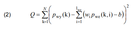
where: N – number of values (samples).
This indicator has one minimum, which ensures finding a global solution. The values of the coefficients wi and b are calculated by means of the iterative method, according to the relations (3) and (4):
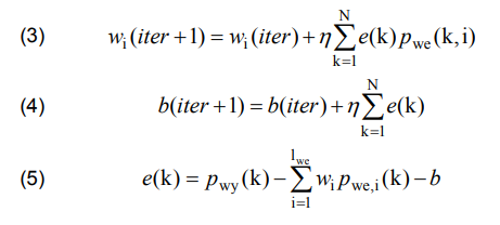
where: iter – iteration no., η – teaching speed factor, e(k) – teaching error.
Due to the relations (1)÷(5) an estimation algorithm based on ANN (EA-ANN) was developed.
Analysis of the results of estimation for selected indicators, for real conditions of the distribution network operation
The tests were carried out in two different test networks (parts of the DSO network): in a network with a high power load reception, strongly affecting the operator’s system (the test network no. 1) and in a network, where there were no PQ problems (the test network no. 2).
Evaluation of values calculated by the developed EAANN was carried out on the basis of the estimation accuracy coefficient and by comparing statistic numerical measures laid down in the regulation [2] and the standard [3] for selected PQ indicators respectively (percentile 5% and 95%, marked as CP05 and CP95). Statistical measurements were calculated for real values of selected PQ indicators and for values returned by EA-ANN at the power grid points without a measuring instrument (target).
Test network no. 1
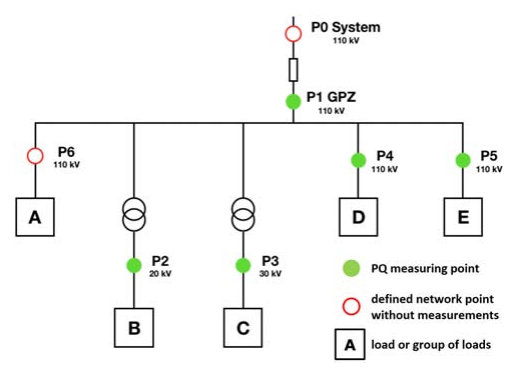
The case under consideration concerns the power supply system of a large industrial customer supplied from the 110 kV level, having an internal MV distribution network with varied voltage levels. In the recipient’s power supply system there is a large disturbing load affecting the operator’s system heavily. Figure 1 presents a simplified diagram of a part of the considered power supply system with marked points, where the analyzers are connected – P1 to P6.
Class A PQ analyzers were installed at six points of the power supply system under. Measurements and recordings lasted six weeks. Verification of the values estimated by the EA-ANN, for the case without a measurement at a particular point, is the final result of the algorithm. The following figures show the results obtained, for:
– the factor Pst,P2 at a point P2 – 20 kV on the grounds of the point P1 – 110 kV – Pst,P2 = f(Pst,P1) – Fig.2,
– the factor Pst,P3 at a point P3 – 30 kV on the grounds of the point P1 – 110 kV – Pst,P3 = f(Pst,P1) – Fig.3,
– the factor K2U,P3 at a point P3 – 30 kV on the grounds of the point P1 – 110 kV – K2U,P3 = f(K2U,P1) – Fig.4,

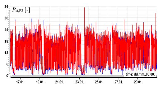

In figures 2, 3, 4, the measured values are presented in blue and the estimated values in red (this also applies to figures 6, 7, 8). The values of the validity coefficient, CP95 and a relative error calculated for actual and estimated runs are shown in table 1.
Table 1. Overview of the validity coefficient values, CP95 and the relative error – test network no. 1
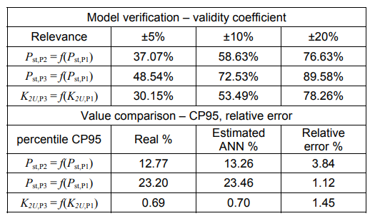
The relative error for CP95 is between 1.12% and 3.84%. Therefore, the CP95 values calculated on the basis of the estimated values do not deviate significantly from the CP95 values determined on the grounds of the measured values.

Test network no. 2
The case under consideration concerns a part of MV – 20 kV distribution network (one outlet from the main power supply point, approx. 6.5 km long). No significant disturbance sources were found in this system. Figure 5 shows a simplified diagram of the network under consideration. There is marked location of the stationary PQ analyzer (point A) and the electric energy meter (point L) at 20 kV level, and E1, E2 and E3 points at 400 volts level, for which the values are estimated. Measurements and recordings were carried out 4-5 weeks. Estimation was made of the value for:
– voltage rms UnN,E1 at point E1 400 V, on the grounds of the point A 20 kV – UnN,E1 = f(USN,A),
– voltage rms UnN,E2 at point E2 400 V on the grounds of the point L 20 kV – UnN,E2 = f(USN,L) – Fig. 6,
– THDU-nN,E1 at point E1 400 V on the grounds of the point A 20 kV – THDU-nN,E1 = f(THDU-SN,A) – Fig. 7,3
– Pst-nN,E3 at point E3 400 V on the grounds of the point A 20 kV – Pst-nN,E3 = f(Pst-SN,A) – Fig. 8,
– 7. harmonic HU7-nN,E3 at point E3 400 V on the grounds of the point A 20 kV – HU7-nN,E3 = f(HU7-SN,A) – Fig.9.
Figures 6, 7, 8 show a comparison of the real values (measured, blue) and the estimated values. The values of the validity coefficient, CP95 and CP05 and the relative error calculated for real and estimated runs are presented in the Table 2. The relative error for CP95/CP05 for voltages does not exceed 0.03%, which is low. The relative error for CP95 for other PQ indicators does not exceed 8.33%. Larger error values apply to a percentile CP05 (not presented in Table 2). They result from low levels of indicator values.
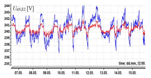
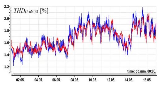
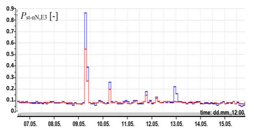
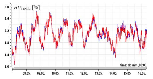
Table 2. Summary of values: validity coefficient, CP95 and CP05 and the relative error – test network no. 2

Conclusions
Analysis of the results acquired from the developed algorithm of estimation of PQ coefficient values using the concept of artificial neural networks enables their positive evaluation. The absolute errors of the estimated statistical values of CP95 and CP05 statistical measures range from 0.0% to 8.33%. After exclusion of the case for the low level of Plt,CP95 = 0.12 coefficient (in practical terms it is a very low value), for which the limit value is 1.0, the relative error interval goes down to 4.86%. The proposed approach may be an alternative or supplementation to the results acquired from the simulation of a power grid model that needs to be built earlier in a selected programming environment.
REFERENCES
[1] Technical Specification for tender procedures for the supply of metering infrastructure for AMI systems in the Polish market – Annex 1 – power quality indicators (in Polish), Urząd Regulacji Energetyki URE, (2015)
[2] Regulation of the Minister of Economy dated 4 May 2007 on detailed conditions for the operation of the power supply system (in Polish), (2007)
[3] PN-EN 50160 – Voltage supply parameters in public power supply networks
[4] Gała M., Application of artificial neural networks to assess the impact of non-linear receivers on the electric energy quality (in Polish), Przegląd Elektrotechniczny, 87 (2011), No. 6, 40-46
[5] Gała M., Application of neural method of voltage estimation to evaluation of influence of nonlinear loads on electric energy quality, 10th International Conference on Electrical Power Quality and Utilisation EPQU 2009, IEEE Conference Proceeding, (2009), 1-6
[6] Eremia M. (Editor), Liu Ch., Edris A., Advanced Solutions in Power Systems: HVDC, FACTS, and Artificial Intelligence, IEEE Press, Wiley, (2016)
[7] Firlit A., Świątek B., Piątek P., Dutka M., Siostrzonek T., Estimation of selected power quality indicators at unmetered distribution network points (in Polish), Zeszyty Naukowe Wydziału Elektrotechniki i Automatyki Politechniki Gdańskiej, 67 (2019), 17-20
Authors: dr inż. Andrzej Firlit, e-mail: afirlit@agh.edu.pl; dr inż. Bogusłąw Świątek, e-mail: boswiate@agh.edu.pl; prof. dr hab. inż. Zbigniew Hanzelka, e-mail: hanzel@agh.edu.pl; dr inż. Krzysztof Piątek, e-mail: kpiatek@agh.edu.pl; mgr inż. Mateusz Dutka, email: mdutka@agh.edu.pl; dr inż. Tomasz Siostrzonek, e-mail: tsios@agh.edu.pl; AGH University of Science and Technology, al. Mickiewicza 30, 30-059 Krakow, Poland.
Source & Publisher Item Identifier: PRZEGLĄD ELEKTROTECHNICZNY, ISSN 0033-2097, R. 96 NR 5/2020. doi:10.15199/48.2020.05.07
