Published by Marian HYLA, Silesian University of Technology, Department of Power Electronics, Electrical Drives and Robotics. ORCID: 0000-0001-6466-7398
Abstract. The paper presents the issues of the influence on the supply electrical power grid of the thyristor rectifier supplying high power receivers such as a shaft hoisting machines in mining. The current distortion influence of the non-linear load on the quality of electricity in the plant’s power grid was presented. Methods of higher harmonics filtration of the current supplying the hoisting machine are discussed. The results of control tests of the effectiveness of shunt passive higher harmonic filters after changing the configuration of the power grid of the mine are presented.
Streszczenie. W artykule zaprezentowano zagadnienia wpływu na sieć zasilającą przekształtników tyrystorowych zasilających odbiorniki dużej mocy jakimi są szybowe maszyny wyciągowe w kopalniach. Przedstawiono wpływ zniekształcenia prądu odbiornika nieliniowego na jakość energii elektrycznej w sieci zakładu. Omówiono metody filtracji wyższych harmonicznych prądu zasilającego maszynę. Zaprezentowano wyniki badań kontrolnych skuteczności działania pasywnych filtrów równoległych/gałęziowych wyższych harmonicznych po zmianie konfiguracji sieci elektroenergetycznej kopalni. (Filtracja wyższych harmonicznych w układzie zasilania tyrystorowej maszyny wyciągowej transportu szybowego w kopalni)
Keywords: hoisting machine, thyristor rectifier, harmonic filtration, passive harmonic filters
Słowa kluczowe: maszyna wyciągowa, prostownik tyrystorowy, filtracja harmonicznych, filtry pasywne
Introduction
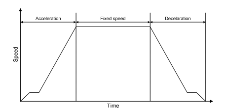
In industrial electrical power grids, the sources of higher harmonics are usually power electronic converters supplying high power loads. Typical devices are hoisting machines in mine shaft transport systems with DC motors powered from the 6 kV power grid through the 12-pulse thyristor rectifiers. Machine speed regulation is achieved by changing the thyristor firing angle in accordance with the so-called a travel diagram taking into account allowable accelerations and decelerations as well as speed stabilization during the steady driving operation. An example of a hoisting machine travel diagram is show in Figure 1.
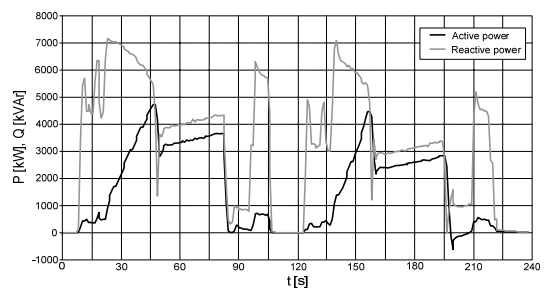
The relatively high engine power of mine hoisting machines with a short and often repetitive cycle of operation makes them as nonlinear loads, with a significant impact on the supply power grid, being the source of higher harmonics and voltage fluctuations [2, 3]. These have a negative impact on the electrical energy quality and may result in financial penalties for failure to meet the appropriate parameters at the point of plant supply. Figure 2 shows an example of the active and reactive power waveforms of the hoisting machine during 2 work cycles.
The distorted current consumed by the rectifier causes a voltage drop on the power grid impedances, which in turn causes also distortion of the supply voltage. The shape of the supply voltage is also influenced by the phenomenon of the commutation voltage drop associated with the switching of the current between the individual thyristors of the rectifier.
Figure 3 shows a diagram of a 12-pulse rectifier consisting of two 6-pulse rectifiers connected in series on the DC side, supplying motor of the hoisting machine. The bridges are supplied from separate rectifier transformers with appropriate connection groups, which enable the voltage shift by an angle of 30°.
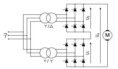
The 12-pulse rectifier compared to the 6-pulse rectifier is characterized by a reduced content of current harmonics generated to the power grid and the suppression of the 3rd harmonic and its multiples by transformers with an appropriate group of connections. It also enables theoretically the elimination, but in practice a significant reduction of 5th and 7th order harmonics with common control of thyristors firing angle (two six-pulse groups must operate with the same firing angle).
The disadvantage of multi-pulse rectifiers is their sensitivity to load unbalance and voltage imbalance or distortion. In this case, for a 12-pulse rectifier, non-characteristic 5th and 7th harmonics may occur, which increases the THDi factor and may lead to exceeding the assumed power quality parameters [2, 4]. Such a case often takes place in power grid with many nonlinear high-power loads, in particular supplied from thyristor rectifiers.
In the power supply systems of mine hoisting machines, in order to reduce the reactive power consumed by the machine, the sequence control of 12-pulse converters is used, which results in the presence of the 5th and 7th harmonics in the supply current.
In the middle-voltage power supply systems of hoisting machines, rectifiers with more than 12 pulses are practically not used. This is mainly due to the increase in the costs of such solutions with a slight improvement in the quality of electricity parameters. The 12-pulse converter is a compromise between limiting the impact on the supply grid and the simplicity of the system, investment and operating costs of the drive [1]. However, this has consequences in the form of a negative impact of the drive on the supply power grid.
In 12-pulse rectifiers of mining hoisting machine drives the three-winding transformers are not used. Separate transformers for each of the rectifiers allow emergency operation of the hoisting machine in case of failure of one of the converters or power transformers. In this case, the machine is powered by a 6-pulse rectifier. However, this results in a reduction of the machine speed and an increase in harmonics generated to the power grid.
The paper presents the issues of the occurrence and elimination of higher harmonics generated by the thyristor power supply system of the hoisting machine and the results of the use of passive shunt filters in one of the hard coal mines in Poland.
The influence of converters on the supply power grid and other devices
Power electronic converters are non-linear loads for the supply power line.
The thyristor rectifier causes many negative phenomena in the supply power grid, e.g. voltage distortion in the supply line, which may cause disturbances in the operation of other devices, in particular related to synchronization errors as a result of distortion of the synchronizing signal in the vicinity of the zero crossing which can lead to asymmetry in the thyristor/transistor switching of the voltage-synchronized converter’s. Operation result of the converter in such conditions may be the generation of non-characteristic harmonics, including even, triple orders and interharmonics 2, 4].
Higher harmonics can cause resonance phenomena in cable lines with large inter-line capacities, which can lead to overvoltages at certain points in the power system. They can also lead to overload of capacitor banks not protected by chokes, used for reactive power compensation and, consequently, to their emergency shutdown or damage.
The distortion of the converter current adversely affects the magnetic elements, causing an increase in losses in transformers and chokes (e.g. eddy currents, connections and structural parts stray losses) [5], which results in an increase in their operating temperature and, consequently, a shortened service life or the possibility of damage. In practice, the current distortions may cause even several times increase in additional power losses in magnetic elements. These reduces the efficiency of not only the drive system powered by the converter, but also the energy efficiency of the entire system due to increased losses in transformers and other devices [4, 7, X].
In rotating machines powered from the same transformer as the converter system, parasitic torques may arise produced by higher harmonics. These torques may be directed opposite to the torque from the fundamental harmonic. Parasitic torques from higher harmonics also increase the vibration of the drive system, which can lead to premature wear of the machine bearings. The efficiency of induction motors supplied from the same system as the source of higher harmonics is also reduced [3].
Harmonics of higher order may cause disturbances in the operation of telecommunications systems.
The inductive reactive power consumed by the converter causes voltage drops on the reactance elements of the grid. At the same time, the change of the thyristor firing angle, e.g. during the starting or braking of the hoisting machine, causes that these phenomena are dynamic, and the time-varying reactive power load may cause voltage fluctuations in an unacceptable range, especially in the grid with low short-circuit power.
One of the criteria for assessing the multi-pulse converters for power supply of hoisting machines is the level of their negative impact on the power supply grid presented in numerical terms. To assess the distortion of current and voltage waveforms, the total harmonic distortion (THD) and the values of individual harmonics are used, with separate analysis of current distortions and voltage distortions resulting from the current flow through the reactances of the supply power grid.
Regardless of the individual harmonic or THD values resulting from any standards (IEEE 519-2014, EN 50160, PN-EN 61000-2-4 etc.) it can be noticed that the aim is to ensure the proper quality of electricity by forcing the effective elimination of current and voltage distortions at the plant’s supply point as well as in its internal power grid.
Methods of higher harmonics reduction
There are many methods of limiting the current harmonics of power electronic converters with various effectiveness and which is of great importance with various investment and operating costs [8, 9].
The simplest method are AC or DC chokes applying which, depending on the choke’s reactance, allowing for a certain reduction of current harmonics. This solution is currently not widely used due to its low effectiveness with the applicable power quality requirements and due to the increase in voltage drop across the reactor along with its impedance increase.
A technically simple and frequently used solution is passive harmonic filters. Such filters are constructed as simple shunt, series, double tuned or broadband filters [10- 18]. There are also solutions with a more complex topology of LC elements connection, which are a combination of several types of passive filters, or a combination of passive filters with additional series chokes (input and output) enabling the shaping of the attenuation bandwidth and preliminaty partial limitation of higher order harmonics [4, 19].
Passive shunt filters are systems with series connection of LC elements, connected in parallel with a non-linear load, creating a resonant circuit with a specific natural resonant frequency [19, 20]. For frequencies lower than the natural resonance frequency, the filter is capacitive, compensating the inductive reactive power in the grid. For higher frequencies, the filter is inductive and prevents resonance in the circuit capacitors – supply power grid [2]. Such a filter is tuned to a harmonic frequency slightly lower that the desired frequency that has to be eliminated. If it is necessary to filter several harmonics, multi-branch systems are built, in which each branch is tuned to a different resonant frequency.
Currently, in industrial grids with non-linear high-power loads, for economic reasons, almost exclusively resonant shunt filters [19, 21, 22] are used, which for a selected frequency constitute a low-impedance branch shunting the impedance of the supply grid, which in ideal conditions means that the current of a specific harmonic is shortened in the filter branch and is not present in the supply power grid.
Active filters are a much more expensive solution, however they enable effective elimination of both higher harmonics and reactive power generated by converter systems. Active filters are usually built as shunt filters [8-10, 17, 22, 23]. Active filters work by eliminating the components that are not active currents, i.e. those components that are not in phase with the appropriate voltage.
Active filters are power electronic devices that generate a current that is in opposite phase to the undesirable components of the load current, thanks to which a sinusoidal current is obtained at the supply point of the filter – non-linear load system. There are many designs of active filters and many methods of controlling the filter’s power electronic switches. The vast majority of these are VSI systems.
The high switching frequencies of active filter transistors may result in an increased level of higher order harmonic distortion and the emission of EMC disturbance, but appropriate filter control causes them to lie above the frequencies covered by the power quality standards. Unlike passive filters that filter only harmonics with dominant values, active filters are able to filter out a wide spectrum of undesirable frequencies, and thus allow to maintain a low level of harmonics in the full load range [4].
Hybrid systems consisting of passive and active filters are also used [9, 17, 22-24]. In these solutions, the active part of the filter can be connected to the passive part in series or in parallel. The passive part is used to eliminate the dominant lower-order harmonics, and the active part is used to eliminate the rest. This allows to reduce the power and thus the cost of the active part of the filter.
Passive straight filters
The most common method of filtering higher harmonics in hoisting machines are multi-branch passive resonant shunt 2nd order filters. The individual filter branches are tuned to the appropriate frequencies.
Most often, the system consists of branches that include the filters of 5th and 7th harmonic or the 5th, 7th, 11th and 13th harmonic, regardless of whether 6-pulse or 12-pulse rectifiers are used.
In practice, in a 12-pulse rectifier appear the currents of uncharacteristic 5th and 7th harmonics which cannot be omitted. The use of 5th and 7th harmonic filters eliminates the possibility of parallel filter resonance with the power grid near these frequencies [2, 16].
In the case of hoisting machines, the expected level of harmonics should also be taken into account at the sequence control of 12-pulse converters and during emergency operation of the machine when the motor is powered from a single 6-pulse rectifier.
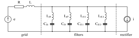
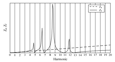
Figure 4 shows a single-phase equivalent diagram of the power grid [21], and Figure 5 shows an example of the frequency response of a grid with a 4-branches passive higher harmonic filter [14, 21].
When calculating the filter parameters, apart from the expected harmonics of the compensated load, one should also take into account the harmonics generated in other points of the power grid, because they may cause an increase current of the filter branch, and thus an increase temperature of the choke or tripping of the overcurrent protection. As a result of activation of the protection, the filter is switched off and all harmonics generated by the loads get into the grid.
In the hoisting machinery power supply systems, due to its short operating cycle, these filters are switched on permanently. Possible switching off the filter may take place with excess of the reactive power in the grid during longer machine downtime. In this case, sections in order from the highest harmonic to the lowest are switching off, until the appropriate power factor is obtained at the point of common coupling. The filter sections are switched on in the reverse order. A certain inconvenience is the necessity to turn on the filters while the hoisting machine is working, which limits the possibility of using them to regulate the reactive power in the plant’s grid.
The effectiveness of the filter depends on the impedance of the power grid at the point of its connection [2, 5, 12]. Usually, this value is not known exactly, and additionally it changes with changing the configuration of the supply grid.
Filters become detuned as a result of changes in the supply frequency and changes in the parameters of the filter elements, e.g. as a result of the aging process of the capacitors. For these reasons, filters of this type are tuned to a frequency slightly lower than the frequency of the harmonic need to be eliminated.
Filter parameters may also differ from the optimal values due to tolerances of individual components parts in production process.
These phenomena reduce the effectiveness of the filter.
The following part of the paper presents the results of the control tests of the higher harmonic filtering efficiency of a hoisting machine powered by a 12-pulse rectifier in one of the hard coal mines in Poland. The tests were aimed at checking the impact of the drive on the supply power grid after changing its configuration, and thus changing the impedance at the filter connection point.
Measurement results
Figure 6 shows a simplified diagram of the mine’s power grid.
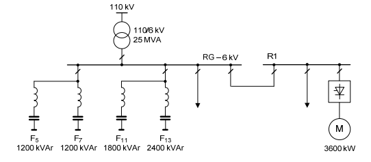
The object of the research was a hoisting machine with a direct current motor with a power of 3600 kW powered by a 12-pulse thyristor rectifier and a set of shunt passive filters.
Measurements were made in the bays of the main RG switching station. The line-to-line voltage waveform on the RG main switchgear busbars and the current waveforms in the 110/6 kV transformer supply bay and the R1 switchboard supply bay were recorded. The measurements were carried out while hoisting machine run in fixed speed 16 m/s with the filters turned off and the relevant filter sections turned on. The hoisting machine was driven at the full load. Harmonic analysis was performed up to a frequency of 1600 Hz. The tests were carried out during the normal operation of the plant.
It should be noted that the hoisting machine is the largest unit load, but other loads with a total power greater than the power of hoisting machine are also important, which affects the content of higher harmonics of the transformer supplying the system. During the tests, the average load of the transformer was approx. 9.5 MVA.
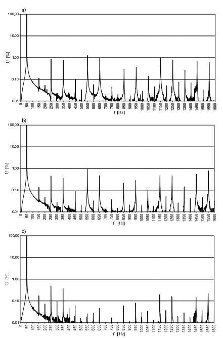
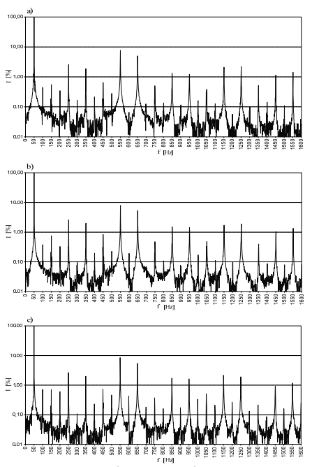
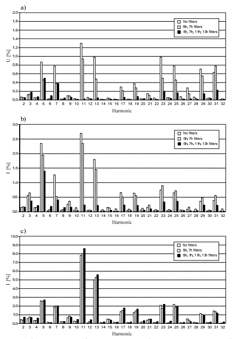
Figures 7-9 show on a logarithmic scale the harmonics spectra for individual analyzed cases.
Table 1 presents the synthetic results of the harmonic analysis for the cases shown in Figures 7-9.
Table 1. Results of the harmonic analysis for a fixed speed driving
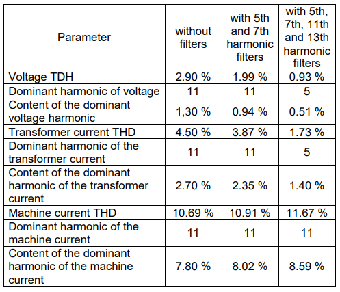
The effects of the filters can be observed by comparing the measurements during the operation of the hoisting machine and switching on of subsequent filter sections. As can be seen from the values presented in Table 1, switching on next section of the filter causes a decrease in THDu and THDi values in the 110/6 kV transformer bay. The percentage content of higher harmonics in the supply transformer current is small and does not exceed the permissible values with harmonic filters turned off or on. However, with a reduced load of other devices, this share will increase and during operation with filters switched off, it may exceed the permissible values. Therefore, the filters should be switched on when the hoisting machine is running.
Figure 10 shows, on a linear scale, a comparison of the content of higher harmonics for different operating states of the filters for fixed speed operation of hoisting machine.
As can be seen in Figure 10c), the harmonic content of the current in the bay supplying the hoisting machine through the R1 switchgear practically does not change. Minor changes are caused by a change in the impedance of the circuit power grid-harmonic filters when switching on subsequent filter sections [14].
Figure 11 shows the current waveform in the bay supplying the R1 switchgear, and Figure 12 shows the voltage waveforms on the RG switchgear busbars during the fixed speed operation of hoisting machine for selected filter configuration cases.
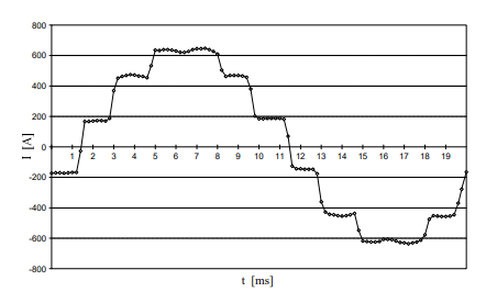
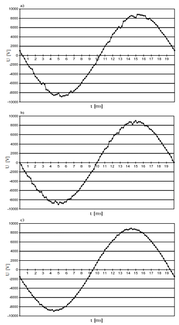
Based on the analysis of the voltage and current waveforms of thyristor rectifier supplying the hoisting machine, no excessive distortions of these waveforms were found. The waveform of the current supplying the machine practically does not change when next sections of the filter are turned on. The next filter sections turning on smooths the supply voltage waveform.
The currents of selected harmonics flow through properly tuned filter sections and practically do not cause voltage distortions on the reactances of the supply power grid The control measurements confirm the correct operation of the installed filters after changing the configuration of the supply power grid, resulting in the limitation of the appropriate current and voltage harmonics in the bay of the transformer supplying the RG switchgear.
Summary and conclusions
The paper presents the results of controls tests of the filtration efficiency of higher harmonics of a thyristor hoisting machine in one of the hard coal mines in Poland.
Due to the relatively high power, hoisting machines are one of the most important electricity consumers in mines, affecting the quality of energy. The use of passive multibranch higher harmonic filters, due to their high attenuation and efficiency as well as relatively low cost, is one of the most common solutions used in industrial power grids. Properly calculated filter parameters allow to maintain the proper quality of energy in the power supply and distribution grids. However, due to the aging of passive filter elements and changes in operating conditions when changing the configuration of the supply grid, it is advisable to carry out periodic control measurements of their effectiveness.
The presented control measurements confirm the correct operation of the tested filters and the effective limitation of higher harmonics generated by the rectifier of the hoisting machine after changing the configuration of the power supply grid.
The use of harmonic filters contributes to the reduction of electricity costs by eliminating additional charges related to the failure to meet the quality parameters of energy at the point of supply to the plant and significantly improves the reliability of both the converter system and other devices supplied from the plant’s power grid.
REFERENCES
[1] Siostrzonek T., Chmielowiec K., Piątek K., Dutka M. Firlit A.: The use of multi-pulse systems in the power supply of hoisting machine drives to improve voltage parameters in mining plants, 2020 12th International Conference and Exhibition on Electrical Power Quality and Utilisation- (EPQU), 2020, pp.1-6, doi: 10.1109/EPQU50182.2020.9220301
[2] Varetsky Y., Hanzelka Z.: Filter characteristics in a DC drive power supply system, 2008 13th International Conference on Harmonics and Quality of Power, 2008, pp.1-6, doi: 10.1109/ICHQP.2008.4668842
[3] Gała M., Jagieła K., Kępiński M., Rak J.: Influence of high power DC converters drives on operating parameters of induction machines, (In Polish) Zeszyty Problemowe – Maszyny Elektryczne, no. 76/2007, KOMEL, 2007, pp.35-40
[4] Czornik J., Haltof M.: Harmonic filters in converter drive systems, (In Polish) The Scientific Papers of Faculty of Electrical and Control Engineering Gdańsk University of Technology, vol.67, JDEE Scientific – Technology Conference Power Quality of Electricity Supply – joint responsibility of producers, distributors, consumers and prosumers, 2019, pp.33-38, doi: 10.32016/1.67.06
[5] Hanzelka Z.: Rozważania o jakości energii elektrycznej (V). Wyższe harmoniczne napięć i prądów (In Polish), Elektroinstalator 1/2002, 2002, pp.26-31
[6] Zobaa A. F.: Harmonic problems produced from the use of adjustable speed drives in industrial plants: case study, 2004 11th International Conference on Harmonics and Quality of Power (IEEE Cat. No.04EX951), 2004, pp.6-10, doi: 10.1109/ICHQP.2004.1409320
[7] Habrych M., Wisniewski G., Miedzinski B., Wosik J., Kozlowski A.:, Power loss due to high harmonics in power transformer when use for dc drive of hoisting machines, 2014 International Conference on Information Science, Electronics and Electrical Engineering, 2014, pp.2065-2070, doi: 10.1109/InfoSEEE.2014.6946287
[8] Izhar M., Hadzer C. M., Masri S., Idris S.: A study of the fundamental principles to power system harmonic, Proceedings. National Power Engineering Conference, PECon 2003, pp.225-232, doi: 10.1109/PECON.2003.1437448
[9] Schwanz D., Bollen M., Larsson A.: A review of solutions for harmonic mitigation, 2016 17th International Conference on Harmonics and Quality of Power (ICHQP), 2016, pp.30-35, doi: 10.1109/ICHQP.2016.7783422
[10] Rizk G., Salameh S., Kanaan H. Y., Rachid E. A.: Design of passive power filters for a three-phase semi-controlled rectifier with typical loads, 2014 9th IEEE Conference on Industrial Electronics and Applications, 2014, pp.590-595, doi: 10.1109/ICIEA.2014.6931233
[11] Marz M. B.: Harmonic simulations for filter design at a large industrial load, 2000 Power Engineering Society Summer Meeting (Cat. No.00CH37134), 2000, vol.2, pp.1080-1087, doi: 10.1109/PESS.2000.867528
[12] Campos B. P., Sousa L. A. R., Ribeiro P. F.: Mitigation of harmonic distortion with passive filters, 2016 17th International Conference on Harmonics and Quality of Power (ICHQP), 2016, pp.646-651, doi: 10.1109/ICHQP.2016.7783315
[13] Pravitasari D., Firmansyah E., Haryono T.: Harmonic current elimination in industrial power systems, 2015 2nd International Conference on Information Technology, Computer, and Electrical Engineering (ICITACEE), 2015, pp.358-362, doi: 10.1109/ICITACEE.2015.7437829
[14] Nassif A., Xu W., Freitas W.: An investigation on the selection of filter topologies for passive filter applications, IEEE PES General Meeting, 2010, pp.1-1, doi: 10.1109/PES.2010.5588168
[15] Sanjay J. S., Misra B.: Power Quality Improvement for Non Linear Load Applications using Passive Filters, 2019 3rd International Conference on Recent Developments in Control, Automation & Power Engineering (RDCAPE), 2019, pp.585-589, doi: 10.1109/RDCAPE47089.2019.8979035
[16] Dovgun V., Egorov D., Temerbaev S.: Passive Filtering Systems for Multipulse Rectifiers, 2020 International Ural Conference on Electrical Power Engineering (UralCon), 2020, pp.235-239, doi: 10.1109/UralCon49858.2020.9216291
[17] Ho S., Lam C., Wong M.: Comparison among PPF, APF, HAPF and a combined system of a shunt HAPF and a shunt thyristor controlled LC, TENCON 2015 – 2015 IEEE Region 10 Conference, 2015, pp.1-6, doi: 10.1109/TENCON.2015.7373058
[18] Sachan R., Srivastava R.: Performance analysis of fixed shunt passive filters for harmonic mitigation, 2016 International Conference on Emerging Trends in Electrical Electronics & Sustainable Energy Systems (ICETEESES), 2016, pp.87-90, doi: 10.1109/ICETEESES.2016.7581357
[19] Das J. C.: Passive filters – potentialities and limitations, in IEEE Transactions on Industry Applications, vol.40, no.1, pp.232-241, Jan.-Feb. 2004, doi: 10.1109/TIA.2003.821666
[20] Matyjasek Ł., Matyjasek K.: Power factor correction systems for mining hoists with special consideration of STATCOM systems, (In Polish) The Scientific Papers of Faculty of Electrical and Control Engineering Gdańsk University of Technology, vol.67, JDEE Scientific – Technology Conference Power Quality of Electricity Supply – joint responsibility of producers, distributors, consumers and prosumers, 2019, pp.153-157, doi: 10.32016/1.67.31
[21] Mattavelli P.: Design aspects of harmonic filters for high-power AC/DC converters, 2000 Power Engineering Society Summer Meeting (Cat. No.00CH37134), 2000, vol.2, pp.795-799, doi: 10.1109/PESS.2000.867455
[22] Pogorelov A. V,: Improving Filter-Compensating Devices in Power Supply Systems of Mine Hoists, 2019 International Multi-Conference on Industrial Engineering and Modern Technologies (FarEastCon), 2019, pp.1-4, doi: 10.1109/FarEastCon.2019.8934157
[23] Kedra B.: Comparison of an active and hybrid power filter devices, 2014 16th International Conference on Harmonics and Quality of Power (ICHQP), 2014, pp.556-560, doi: 10.1109/ICHQP.2014.6842771
[24] Solanki J., Fröhleke N., Böcker J.: Implementation of Hybrid Filter for 12-Pulse Thyristor Rectifier Supplying High-Current Variable-Voltage DC Load, in IEEE Transactions on Industrial Electronics, vol.62, no.8, pp.4691-4701, Aug. 2015, doi: 10.1109/TIE.2015.2393833
Autor: dr inż. Marian Hyla, Silesian University of Technology, Faculty of Electrical Engineering, Department of Power Electronics, Electrical Drives and Robotics, ul. B. Krzywoustego 2, 44-100 Gliwice, Poland, e-mail: marian.hyla@polsl.pl
Source & Publisher Item Identifier: PRZEGLĄD ELEKTROTECHNICZNY, ISSN 0033-2097, R. 98 NR 5/2022. doi:10.15199/48.2022.05.08
