Published by Houria SMAIL1, Yassine BENSAFIA2, PaElectrical Engineering Department, Faculty of Sciences and Applied sciences, University of Bouira, 10000 – Algeria (1), PaElectrical Engineering Department, Faculty of Sciences and Applied sciences, University of Bouira, 10000 – Algeria (2), ORCID: 1. 0000-0001-8474-2009; 2. 0000-0003-1760-3636
Abstract. Depending on the power system condition in terms of operating reserves, and equipment availability, the severity of the disturbance may cause parts of the power system to be islanded, or to lose synchronism and enter a complete blackout. The aim of this paper is to design an automatic under frequency load shedding scheme which can be able to safeguard the power system against major disturbance involving multiple contingency events. The proposed load shedding scheme is tested on a real model of network. The simulations were performed on a dynamic model of the power system using the software package SICRE.
Streszczenie. W zależności od stanu systemu elektroenergetycznego pod względem rezerw operacyjnych i dostępności sprzętu, intensywność zakłócenia może spowodować wyspowe funkcjonowanie części systemu elektroenergetycznego lub utratę synchronizmu i całkowitą przerwę w dostawie prądu. Celem tego artykułu jest zaprojektowanie schematu automatycznego odciążania pod częstotliwością, który może zabezpieczyć system elektroenergetyczny przed poważnymi zakłóceniami obejmującymi wiele zdarzeń awaryjnych. Zaproponowany schemat odciążania testowany jest na rzeczywistym modelu sieci. Symulacje przeprowadzono na dynamicznym modelu systemu elektroenergetycznego z wykorzystaniem pakietu oprogramowania SICRE. (Nowe podejście do schematu zrzucania obciążenia)
Keywords: Shedding, defense, frequency, safeguard
Słowa kluczowe: obrona, częstotliwość, zabezpieczenie
Introduction Many studies have been implemented with the aim of power system reliability [1]. A Multi-agent method for service restoration in a complex shipboard power system [2], multi-functional flexible power conditioner [3], V2G (Vehicle to Grid) technology for power system balancing [4], network congestion assessment [5], and time-stamped synchronized measurements [6]. In [7], an algorithm for determining the polygonal and circular tripping characteristics of distance protection was presented. It was demonstrated that, the approach makes it possible to more effectively determine the protection settings that will ensure its correct functioning in an electrical power system.
When the system splits into islands due to a large disturbance, load shedding is the only possible protection. Disturbances that cause the islanding are, in most cases, a trip of a generating unit. The loss of a generating unit in such an island may represent a large percentage of an island’s generation and causes a rapid decline in the frequency. Under such conditions the primary regulation is not adequate, and so we have to use load shedding.
In order to prevent an unwanted frequency decline, we have to detect the under frequency condition and act properly. When the frequency drops to a pre-set limit the load-shedding must be triggered. The load-shedding is performed in several steps with a proper delay and with the correct amount of load being shed. The main purpose of load-shedding is to bring the frequency back to within acceptable limits.
In the first part of the paper we describe the methodology adopted for the design of settings of load shedding scheme, especially the number of load-shedding steps, the size of the load to be shed in each step and the frequency threshold.
In the second part of the paper we describe the considered data network used to test the performance of developed under frequency load shedding scheme.
The last part of the paper deals with simulations of the frequency response following the tripping of a major power plant. Simulations for different scenarios were performed on a dynamic model of the power system in isolated operation using the software package SICRE.
Methodology
In the process of determining the best under frequency load-shedding scheme, we consider the following criteria [8], [9]:
• Fmax: The value of the first threshold of the frequency is generally chosen on the basis of the network experience.
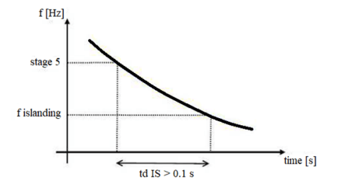
• Fmin: The minimum stage before islanding has to be sufficiently high to avoid that during the delay time of the relays the frequency does not reach the Islanding activation frequency.
• ΔPmax: The amount of load to be shed for each stage has to face to the loss of an entire power plant of medium or large size.
• The number of stages.
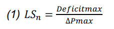
Where Deficitmax is the maximum of load that do not cause reactive violations and over voltage on the HV level.
Deficitmax = 50% of the total load.
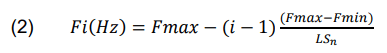
• The frequency threshold for each stage is calculated adopting the uniformity criterion:
• In order to avoid unexpected intervention of load shedding in occasion of electromechanical stable Frequency oscillations, the relay are set with a time delay of 0.1s.
Consider hypothesis
The model of the power system included all the high-voltage levels (60, 90, 150, 220 and 400kV). We assumed an isolated operation for the power system, as there is no need for underfrequency load shedding protection in an interconnected system.
The loads in the power system were modeled by a direct connection to the 60kV level, or to the 220kV, 90kV, 30kV level in some cases. The system loading corresponds to a typical winter day with peak demand.
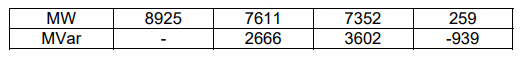
The model of the system includes larger (1200MW) and medium (800MW) power plants which represent respectively 16% and 10% of the total generation. The data are given in the Table 1:
Table 1. Active and reactive power generation, loads and losses
The coefficients of the load model used in the study are given in the Table 2:
Table 2. Load components characteristics.
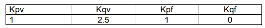
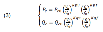
The load dependence on voltage and frequency are given by the following form [10]:
The settings of the turbine governor droop, used are: 5% for gas and steam power plants.
Dynamic simulations
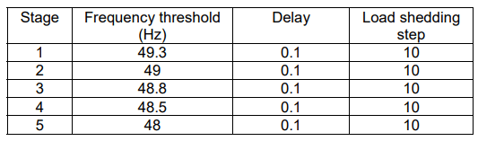
Considering the abovementioned criteria, the settings of the proposed load shedding scheme are given as follow:
Table 3. Load shedding settings
In order to test the proposed under-frequency load shedding scheme we set up several simulating credible and extreme scenarios.
• Credible scenarios are aimed to test the performance of load shedding in case of the most probable events. The credible scenario selected (scenario1) is the loss of 26% of the total generation (2000MW).
• Extreme scenarios are aimed to test the performance of load shedding in case of events that causes the complete operation of the load shedding scheme (activation of all the stages of load shedding). The extreme scenario selected (scenario2) is the loss of 50% of the total generation (3840MW).
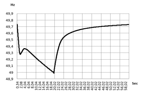
The results for each scenario are presented, respectively in Fig. 2 and Fig. 3.
In the first scenario, Fig. 2, the frequency drops to just under 49Hz. Therefore, 20% (1477MW/729MVAr) of the total load is shed and bring the frequency back above 49.7Hz.
As can be seen in Fig. 3 (second scenario), the full extent of load-shedding is activated, shedding 50% (3692MW/1823MVAr) of the total load. The frequency drops to just under 48Hz, with a delay time of the relay sufficiently short to avoid that the frequency falling below the limits of 47.5Hz.
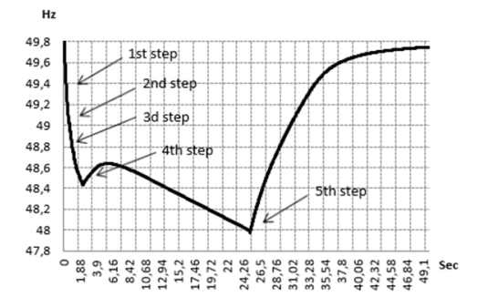
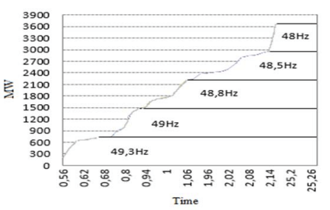
The frequency stays above the limits and bringing back to within acceptable limits, so the scheme is considered successful. A schematic illustration of the amount of the load to be shed for different steps is shown in Fig.4.
Conclusion
The aim of this paper was to design an automatic under frequency load shedding scheme which can be able to safeguard the power system against major disturbance involving multiple contingency events.
Using dynamic simulations of the power system to test the proposed load shedding scheme, the results showed that the scheme was able to prevent an intolerable frequency drop during exceptional events with a significant production deficit in the island.
REFERENCES
[1] Smail H., Alkama R., Medjdoub A., Optimal design of the electric connection of a wind farm, Energy, 165 (2018), 972-983
[2] Hengxuan L., Haishum S., Jinyu W., Wei Y., Qian W., A MultiAgent Based Method for Service Restoration in Shipboard Power System, Przegląd Elektrotechniczny, 88 (2012), nr 6, 354-359
[3] Chen Z., Zou X., Duan S., Wei H., Research on excitation control system of multi-functional flexible power conditioner, Przegląd Elektrotechniczny, 87 (2011), nr 4, 172-175
[4] Jozwiak D., Drechny M., Analysis of the possibilities of using V2G technology for power system balancing, Przegląd Elektrotechniczny, 95 (2019), nr 10, 60-63
[5] Smail H., Alkama R., Medjdoub A., Impact of large scale power plant connection on congestion in the algerian electricity transmission system, Energy, 159 (2018), 115-120
[6] Szewczyk M., Time synchronization for synchronous measurements in Electric Power Systems with reference to the IEEE C37.118TM Standard-selected tests and reommendations, Przegląd Elektrotechniczny, 91 (2015), nr 4, 144-148
[7] Andreev M., Suvorov A., Ufa R., Razzhivin I., Relay Protection Settings Determination Using Its Mathematical Models, Przegląd Elektrotechniczny, 97 (2021), nr 6, 140-143
[8] Cignatta M., Salvetti M., Designing Defence Plans – Design Methodology. CESI, 2009.
[9] Vittal V., Controlled Islanding Followed by Load Shedding Based on Rate of Frequency Decline. PSERC Internet Seminar, October 1, 2002.
[10] MEDRING Project. Loads model in sicre and important parameters CESI, 2009.
Authors: Dr.Houria Smail, Bouira University 10000, Algeria, E-mail : h.smail@univ-bouira.dz ; Dr. Yassine Bensafia, Bouira University 10000, Algeria, E-mail : y.bensafia@univ-bouira.dz Or bensafiay@yahoo.fr (Corresponding author);
Source & Publisher Item Identifier: PRZEGLĄD ELEKTROTECHNICZNY, ISSN 0033-2097, R. 100 NR 6/2024. doi:10.15199/48.2024.06.45
