Published by 1. Ilham Bouaissi1, 2. Ali Rezig1, 3. Said Touati2, L2EI Laboratory, University Mohammed Seddik Benyahia, Ouled Aissa. Bp 98, Jijel, 18000, Algeria (1). Nuclear research center, Birine, Ain Oussera. Bp 180, Djelfa, 17200 Algeria (2) ORCID: 1. 0000-0001-5981-6918
Abstract. One of the problems with induction motors, say the experts, is voltage. Insulation deterioration is brought on by the winding overheating because the issue is frequently one that is defective, old, or damaged as a result of voltage surge, voltage drop, or overheating. In this study, we follow the stator winding insulation of an AC machine using leakage current insulation measures. Then the insulation life of the induction motor was determined under different loading scenarios, such as voltage fluctuations and varied modulation frequencies
Streszczenie. Eksperci twierdzą, że jednym z problemów związanych z silnikami indukcyjnymi jest napięcie. Pogorszenie stanu izolacji jest spowodowane przegrzaniem uzwojenia, ponieważ często problemem jest wadliwe, stare lub uszkodzone w wyniku skoku napięcia, spadku napięcia lub przegrzania. W tym badaniu śledzimy izolację uzwojenia stojana maszyny prądu przemiennego za pomocą środków izolacji prądu upływu. Następnie określono żywotność izolacji silnika indukcyjnego w różnych scenariuszach obciążenia, takich jak wahania napięcia i różne częstotliwości modulacji (Prognozy pogorszenia się izolacji uzwojeń silników indukcyjnych pod wpływem wahań napięcia)
Keywords: leakage current – lifetime – voltage fluctuations – frequency modulation.
Słowa kluczowe: prąd upływu – dożywotni – wahania napięcia – modulacja częstotliwości.
Introduction
Among the problems of the motors, the problem of voltage fluctuation is one of the most frequently complained of in the induction motor [6-10]. The mechanical and electrical aspect with bearing fatigue wear and deterioration of the stator insulating materials are the two main factors that cause a squirrel cage induction motor to fail [10-15]. There are many variables that affect motor insulation life, including electrical stress, temperature rise due to variations in motor structure, and operating environment.
Insulation damage is one of the biggest defects of the stator part of the electrical machine, with statistics reaching 38% of failures [1], lack of initial intervention and maintenance causes major malfunctions and stops the operation of the machine, whether in the field of high-voltage machinery or low voltage, therefore, it is essential to monitor the insulation condition and detect faults [2-3]. Detecting the isolation line and its deterioration and predicting the remaining life became necessary in order to improve the reliability of the systems. Therefore, for this purpose many articles proposed different methods and techniques to detect deterioration of insulation. The insulation of electrical machines is subject to several different stresses and are in operation such as electrical, thermal, chemical, environmental, etc [4-5], causing the insulation to break down.
To comprehend the change that takes place in the electrical properties of the insulation, Sumislawska and all successfully carried out an experiment focused on the impact of accelerated thermal aging on the winding insulation. Calculating the isolation’s RUL is the goal [21]. William and al employed an online method to measure the leakage current that was observed to drop as the insulation deteriorated in the inverter-driven electric machine. Using the leakage current’s transient peak as a predictor of degradation. To calculate the RUL, use the EKF technique to cross the peak leakage current [22]. In the second research, William and all of the authors computed the (RUL) by utilizing the online technique for inverter-driven machines of stator insulation, where the real dV/dt of the switching device is taken to be constant. Leakage current, which flows from the inverter and is created by the PWM voltage source applied to the machine, is employed as a signal to detect dielectric change of state and its dissolution. When leakage current is simulated, the resulting signal is a low transient wave that jumps from peak to peak and represents the degradation of the isolation condition. Three experimental tests with three machines each were employed in this paper, the experiments were carried out until the insulation failure was identified in order to know the changes in the insulation properties and how thermal stress degraded them for each stator, which was then placed in the environmental chamber with a temperature distinct from the other tests [23]. In the third research, it is suggested that William and come up with a different way to predict the deterioration of the insulation. This method involves measuring the current of the electric machine that is driven by the current transformer MOSFET in order to distinguish between the deterioration of the insulation and the deterioration of the MOSFET. In this study, isolated deterioration and MOSFET degradation are differentiated using the increasing threshold voltage (vth) with gate oxide dissolving. Experimental studies were used to support the suggested approach [24]. To predict the deterioration of insulation in electrical equipment to the online evaluation, Armando and Sidelmo have completed a novel work. Where linear stochastic models, autoregressive moving averages, and artificial neural networks are used to calculate the time to failure (TF) of isolation. By measuring the leakage current’s resistance (IR) and capacitance (IC), the proposed method uses a high-sensitive current transformer (HSCT) and a conventional voltage transformer (VT) to evaluate the insulation condition in real time. This information is used to identify the stress factor affecting the insulation [25]. To track the insulation of the ground wall, Igor Tsyokhla and others have suggested a technique of accelerated aging applied to the stator of the inverter-fed machines. The capacity of the floor wall and the dissipation factor were measured as indicators to know the insulation state based on the experimental work [26]. The work presented by Sang Side addressed an online monitoring system for three-phase ac machine stator winding ground wall (GW) and phase-to-phase (PP) insulation. Dissipation factor (tan), capacitance, and ac insulation resistance are three indications he used to determine the isolation status. To do this, a method for calculating the current differential leakage current for each phase is developed. In order to present the guidelines for interpreting the change in indicators (Ceq, Req, or DF) and to identify the primary dielectric aging mechanism, this is done with the aid of both offline and online testing. The conclusion of the difference in indicators is in each of the two mentioned tests (online and offline) [27]. Fernando and coworkers evaluated conditions of insulation breakdown owing to moisture using DC ramp, insulation resistance (IR), and frequency domain spectroscopy (FDS) as indicators. They carefully tested the generator by periodically wetting, drying, and aging the electric system; the work was broken down into several tests in order to achieve a discernible difference in the isolation state and to identify the indicator that provides useful information about the isolation state [28]. Andrew and Elias, introduced advanced technology to predict the deterioration of stator winding insulation and calculate the remaining useful life (RUL), the values of capacitance and resistance are calculated from the work of a finite element model (FEM) where it is observed that their values change with the change of the insulation state through these values it calculates the leakage current, initially, this method diagnoses the isolation of the stator by calculating the measures the magnitude of the leakage current in the transient wave, in order to predict the deterioration of the insulation [29].
The operational temperature value has a complete bearing on how quickly insulation ages. The state of the insulation and the expected lifespan of an induction motor can both be assessed using temperature as a proxy.
On the other hand, the bulk of the total energy loss is due to copper loss. As a result, a combination of electrical model, thermal model, and lifetime model can be used to determine the life span of an induction motor. In this paper, we have calculated the aging life of an induction motor through the relationship between the electrical model and the thermal model [30]. The rest of the paper is organized as follows, Section 2 Assessment of isolation status based on isolation system model, Section 3 Induction Motor Lifetime Estimation, and conclusion in Section 4.
INSULATION-SYSTEM
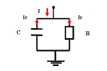
For a good and accurate prediction of isolation status assessment, in this paper we have relied on online monitoring method for isolation monitoring. The technique depends on the calculation of the current difference. The stator isolation can be represented by an equivalent circuit between a resistor and a capacitor in parallel, where the capacitor represents the capacitive coupling and the resistor represents the insulation losses, as shown in figure (1).
Equations
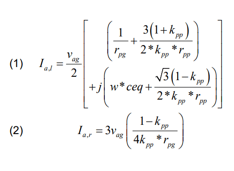
For equations it is recommended to use standard equation editor existing in Word editor (usually it is Math Type editor). The equation editor is defined as follows: font Times New Roman italic, matrix bold, for letters font 10, for index 8, for symbol 12. For example, typical equation should be as:
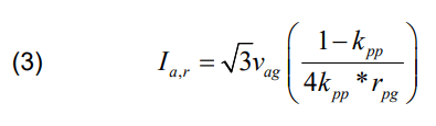
where: Ia,l, Ia,r, Ia,c is the leakage current ,leakage current resistive, and leakage current capacitive, of the phase a respectively, vag and ceq, is the line-to-neutral voltages of phase A, equivalent capacitance, respectively, rpp, rpg, is the resistance between tow phases, resistance between phase and neutr respectively and kpp is the factor.
Figure 2 and 3 represent the wave form of the leakage current in the phase A in the case off-line and on-line, depending on the time and different resistance. Where we notice an increase in the current with a decrease of the equivalent resistance.
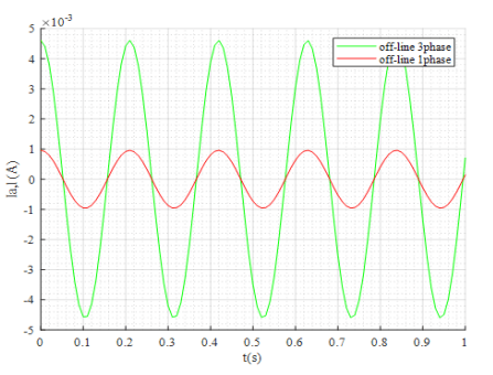
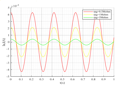
Figure 4 and 5 represent the leakage current resistive, and leakage current capacitive, depending on resistance. Where we notice an decrease in the current with a increase in the intensity of the equivalent resistance on the both cases.
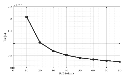
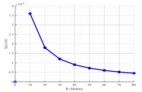
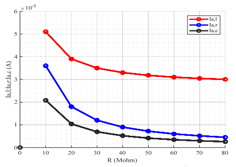
Figure 6 represent the variation of the leakage current ,leakage current resistive, and leakage current capacitive, as a dependent of resistance , where we notice an decrease of the leakage current ,leakage current resistive, and leakage current capacitive, with of resistance increase so the deterioration of the insulation current appears when the current increases leakage.
Induction Motor Lifetime Estimation
The electrical model studies the state of voltage fluctuation and its effect the induction motor behavior, equation waveform of the sinusoidal amplitude modulation is:
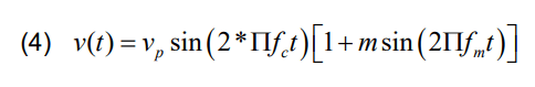
Where:
Vp :is the amplitude of the fundamental AC voltage.
fc :is the fundamental frequency.
Fm :is the modulation frequency.
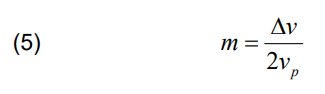
∆V:is the voltage magnitude variation.
m: is the modulation depth.
One of the biggest factors behind electrical energy losses is the high operating temperature of the IM, or so-called copper loss, the copper loss equation from the stator winding of the induction motor is:
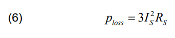
Where Rs and Is is the stator current of the induction motor and the stator resistance of the induction motor respectively.
In order to accurately estimate the lifetime of an induction motor, we used the hybridization method between the thermal model and the electrical model ,the lifetime equation is:
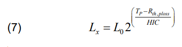
Where: Rth is equivalent thermal resistance (°C/W), HIC, Halving interval [31].
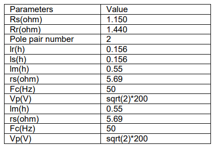
The detailed parameters of the machine are given in table 2, the results of the fault estimation are given in fig. 1, 2 and 3
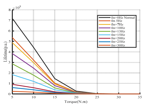
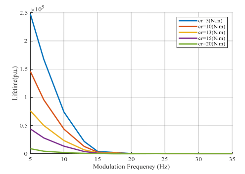
The induction motor lifetime illustrated in figure 7 and figure 8 when it is subject to a 10% and 20% voltage magnitude respectively with load torque gradually increase and different modulation frequency.
We note depending on the calculation of different load torque levels from 5 Hz to 35 Hz the lifetime of an induction motor deteriorates with increasing load torque levels. The stator current RMS values can also be calculated, the figure 7, where for the torque level of the load 5 N.m the value of RMS is 5.7819 (A) and for the level of the load torque of 20 N.m the value of RMS is the 6.8103 A all this in the case of a modulation frequency of 10 Hz.
In the case of a modulation frequency of 20 Hz, the value of RMS at the level of the load torque 5 N.m increase to 6.2464 A, and at the level of the load torque 20 N.m is 7.1722 A etc, and the size of the supply voltage remains constant at 0.1.
The figure 8, for a constant voltage change of 0.2 and a constant load torque of 20 Nm we have at modulation frequency 5 Hz the RMS current value is 7.0055 A and at modulation frequency 15 Hz the RMS value increases to 8.0158 A etc.
The voltage fluctuations significantly affect the life of the induction motor. The modulation frequency change corresponds to the deterioration of the induction motor.
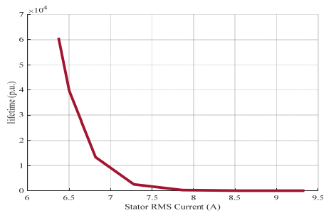
Figure 9. Shows the estimation of the motor lifetime with an RMS current subject to a voltage change of 10% and a modulation frequency of 25 Hz.
Table 1. Three-phase induction motor parameters
Conclusion
In this study, we use leakage current insulation measurements to track the stator winding insulation of an AC machine. Insulation current degrades as leakage current grows. The life of the induction motor has then been further calculated under various load conditions, including voltage changes, as well as under various modulation frequencies. We can immediately anticipate the defect using this technique before development.
REFERENCES
[1] Pillay P., Hofmann P., and Manyage M., (2002). Derating of induction motors operating with a combination of unbalanced voltages and over or undervoltages. IEEE Transactions on Energy Conversion, 17(4), 485-491
[2] Kersting W.H., and Phillips W.H., (1997). Phase frame analysis of the effects of voltage unbalance on induction machines. IEEE Transactions on Industry Applications, 33(2), 415-420
[3] Wang Y.J., (2001). Analysis of effects of three-phase voltage unbalance on induction motors with emphasis on the angle of the complex voltage unbalance factor. IEEE Transactions on energy conversion, 16(3), 270-275
[4] Faiz J., Ebrahimpour H., and Pillay P., (2004). Influence of unbalanced voltage on the steady-state performance of a three-phase squirrel-cage induction motor. IEEE transactions on energy conversion, 19(4), 657-662
[5] Gnaciński P., Hallmann D., Pepliński M., and Jankowski P., (2019). The effects of voltage subharmonics on cage induction machine. International Journal of Electrical Power & Energy Systems, 111, 125-131
[6] Gnacinski P., (2008). Windings temperature and loss of life of an induction machine under voltage unbalance combined with over-or undervoltages. IEEE Transactions on Energy Conversion, 23(2), 363-371
[7] Gnacinski, (2009). Derating of an induction machine under voltage unbalance combined with over or undervoltages. Energy Conversion and Management, 50(4), 1101-1107
[8] L. Tsyokhla, A. Griffo, J. Wang, ‘On-Line Condition Monitoring for Diagnosis and Prognosis of Insulation Degradation of Inverter-fed Machines’, IEEE Transactions on Industrial Electronics .2018,pp.1-10
[9] Rusu-Zagar C., Notingher P., Navrapescu V., Mares G., RusuZagar G., Setnescu T., Setnescu R., G‘Method for Estimating the Lifetime of Electric Motors Insulation’ ,IEEE. Electrical Engineering ,2013,pp.1-6
[10] Lei D., Chen L., and Tang J., (2021). Mining of Weak Fault Information Adaptively Based on DNN Inversion Estimation for Fault Diagnosis of Rotating Machinery. IEEE Access, 10, 6147-6164
[11] Nirwan N.W., and Ramani H.B., (2022). Condition monitoring and fault detection in roller bearing used in rolling mill by acoustic emission and vibration analysis. Materials Today: Proceedings, 51, 344-354
[12] Kudelina K., Baraškova T., Shirokova V., Vaimann T., and Rassõlkin A., (2022). Fault detecting accuracy of mechanical damages in rolling bearings. Machines, 10(2), 86
[13] Bazurto A.J., Quispe E.C., and Mendoza R.C., (2016, October). Causes and failures classification of industrial electric motor. In 2016 IEEE ANDESCON (pp. 1-4). IEEE
[14] M. Riera-Guasp, J.A. Antonino-Daviu, and G.A. Capolino, (2014). Advances in electrical machine, power electronic, and drive condition monitoring and fault detection: State of the art. IEEE Transactions on Industrial Electronics, 62(3), 1746-1759
[15] Godoy W. F., da Silva I. N., Goedtel A., Palácios R. H. C., & Gongora W. S. (2014, July). Neural approach for bearing fault classification in induction motors by using motor current and voltage. In 2014 International joint conference on neural networks (IJCNN) (pp. 2087-2092). IEEE
[16] Sumereder C., ‘Statistical Lifetime of Hydro Generators and Failure Analysis’, IEEE. Transactions on Dielectrics and Electrical Insulation., june 2008,15(3),pp.678-685
[17] Nussbaumer P., Vogelsberger M.A., Wolbank T.M., ’ Induction Machine Insulation Health State Monitoring Based on Online Switching Transient Exploitation’, IEEE. TRANSACTIONS ON INDUSTRIAL ELECTRONICS.,2014 , pp.1-10
[18] Singh G. K., and Ahmed S. A. K. S. A. (2004). Vibration signal analysis using wavelet transform for isolation and identification of electrical faults in induction machine. Electric Power Systems Research, 68(2), 119-136.
[19] Mayoux C., ’Degradation of Insulating Materials under Electrical Stress’ , IEEE .Transactions on Dielectrics and Electrical Insulation., October 2000, 7,( 5),pp. 590-601
[20] A. Elschich, ’Thermo-mechanical Fatigue of Electrical Insulation System in Electrical machines’., PhD thesis 2017
[21] Sumislawska M., Gyftakis K.N., Kavanagh D.F., McCulloch M., Burnham K.J., Howey D.A., ‘The Impact of Thermal Degradation on Electrical Machine Winding Insulation’, int.conf. September 2015
[22] Jensen W.R., Strangas E.G., Foster SH.N., ‘A Method for Online Stator Insulation Prognosis for Inverter-Driven Machines’, IEEE. Transactions on Industry Applications,2018,pp.1-9
[23] Jensen W.R., Strangas E.G., Foster SH.N., ‘Online Estimation of Remaining Useful Life of Stator Insulation’,IEEE .Electrical and Computer Engineering.2017,pp. 635-641
[24] Jensen W.R., Strangas E.G., Foster SH.N., ‘A More Robust Stator Insulation Failure Prognosis for Inverter-Driven Machines’,IEEE .Electrical and Computer Engineering,2019,pp.203-209
[25] Guedes A.S., Silva S.M., ’ Insulation failures prognosis in electric machines: preventive detection and time to failure forecast’, IET Electric Power Applications. Engineering and Technology ,2020 , 14, ( 6), pp. 1108-1117
[26] Tsyokhla I., Griffo A., Wang J., ‘On-Line Condition Monitoring for Diagnosis and Prognosis of Insulation Degradation of Inverter-fed Machines’, IEEE Transactions on Industrial Electronics .2018,pp.1-10
[27] Lee S.B., Yang J., Younsi K., Bharadwaj R.M., ‘An Online Groundwall and Phase-to-Phase Insulation Quality Assessment Technique for AC-Machine Stator Windings’IEEE Transactions on Industry Applications, 42, ( 4), JULY/AUGUST 2006,pp.946-957
[28] Fernando M.A.R.M., Naranpanawa W.M.L.B., Rathnayake R.M.H.M., Jayantha G.A., ’ Condition Assessment of Stator Insulation during Drying, Wetting and Electrical Ageing ’, IEEE ,Transactions on Dielectrics and Electrical Insulation, December 2013,20, ( 6),pp. 2081- 2090
[29] Babel A.S., Strangas E.G., ‘Condition-Based Monitoring and Prognostic Health Management of Electric Machine Stator Winding Insulation’, Department of Electrical and Computer Engineering, 2014,pp.1-7
[30] Zhao K., Cheng L., Zhang C., Nie D., and Cai W., (2017), Induction Motors Lifetime Expectancy Analysis Subject to Regular Voltage Fluctuations. IEEE Electrical Power and Energy Conference (EPEC), pp.1-7
[31] Ayoade M.A., Afolal O.F., Sanusi M.A., and Adebayo M.A., (2018).Determining the Effect of Voltage Variation on Lifetime Expectancy of Induction Motor Using Arrhenius Equation, International Journal of Science, Engineering & Environmental Technology (IJOSEET), 3(8), pp.55-62
Source & Publisher Item Identifier: PRZEGLĄD ELEKTROTECHNICZNY, ISSN 0033-2097, R. 100 NR 1/2024. doi:10.15199/48.2024.01.12
