Published by 1. Justyna HERLENDER, 2. Jan IŻYKOWSKI, Wroclaw University of Science and Technology, Faculty of Electrical Engineering, Department of Electrical Power Engineering Professor emeritus. ORCID 1. 0000-0002-9469-4546; 2. 0000-0002-1048-551
Abstract. This paper presents the algorithm intended for localizing faults in a power transmission line for an inspection-repair purpose. Its innovative element is that a specific input signals of the algorithm have been considered. In particular, incremental positive-sequence voltages and currents taken from directional elements of protective relays installed at both line ends have been taken as the input signals of the localizing algorithm. More general case with regards to synchronism of the measurements is considered, i.e. the measurements acquired asynchronously at both line ends. The fault signals from ATP-EMTP simulations of faults on the sample transmission line were applied for validation of the presented algorithm and for evaluating the fault location accuracy.
Streszczenie. Artykuł przedstawia algorytm przeznaczony do lokalizowania zwarć w elektroenergetycznej linii przesyłowej, z zastosowaniem do celów inspekcyjno-remontowych. Jego elementem innowacyjnym jest to, że rozważono specyficzne sygnały wejściowe badanego algorytmu. W szczególności, przedstawiono zastosowanie przyrostowych sygnałów napięć i prądów dla składowej zgodnej z elementów kierunkowych w przekaźnikach zabezpieczeniowych, zainstalowanych na obu końcach linii, jako sygnałów wejściowych dla algorytmu lokalizującego. Bardziej ogólny przypadek dotyczący synchronizmu pomiarów został rozważony, tj. wzięto pod uwagę pomiary dokonywane na obu końcach linii w sposób niesynchroniczny. Do walidacji przedstawionego algorytmu oraz oceny dokładności lokalizowania zwarć zastosowano sygnały zwarciowe z symulacji zwarć w rozważanej linii przesyłowej, wykonane w programie ATP-EMTP (Lokalizowanie zwarć w elektroenergetycznej linii przesyłowej z użyciem sygnałów z elementów kierunkowych z dwóch końców linii).
Keywords: transmission line, protection, directional element, incremental quantities, fault localizing, fault simulation.
Słowa kluczowe: linia przesyłowa, zabezpieczenie, element kierunkowy, wielkości przyrostowe, lokalizowanie zwarć, symulacja zwarć.
Introduction
Transmission lines play an important role in delivering electrical energy from the generation to consumption centres [1]. Operation of overhead power lines is affected by faults which are of random nature. Demand of a reliable supply for the customers with electrical energy and also power system stability concerns cause that identification of faults becomes of a vital importance. Faults have to be cleared by circuit breakers tripped by protective relays as quickly as possible. Therefore, an identification of faults on a transmission line by protective relays is performed with use of fast measuring and decision making algorithms, operating in on-line regime. Then, a cleared fault has to be located in off-line regime by a fault locator [2]-[6]. Its task is performed for an inspection-repair purpose, what imposes a demand of high accuracy of locating a fault, while its speed is not so critical. The result from a fault locator is utilized for sending a repair crew to remove the fault and thus allowing the line to be switched on again into operation.
Different fault locating methods are known and applied in practice for transmission lines. A main division of them [4] is:
• impedance based methods,
• traveling waves methods,
• reflectometry methods,
• knowledge based methods, i.e. with use of artificial neural networks, fuzzy logic and the other techniques.
Mostly the first two kinds of the above listed methods are in practical use. Especially, the impedance based methods are widely used. They, yield a distance to fault result basing on determining the impedance of the faulted line section in a proportion to the whole line impedance. Such the methods are still considered as quite attractive since they can be embedded into protective relays [7]-[9], thus increasing a functionality of them. This paper is intended to contribute to that by dealing with locating transmission line faults using two-end measurements acquired from protective relays installed at both line ends. Specific input signals of the proposed fault localizing algorithm are taken for consideration. Namely, the incremental positive-sequence voltage and current [10]-[12], which are processed in the directional elements [10] from protective relays installed at both line terminals (Fig. 1) are the algorithm input signals.
The considerations of this paper are related to a faulted transmission network presented schematically in Figure 1. The faulted transmission line of the impedance ZL is between the local (L) and remote (R) buses. It is considered that a fault (F) is placed at a relative distance d [p.u.] (counted from the local bus L). Different kinds of shunt faults are taken into account. Vicinity of the considered transmission line L-R is represented by equivalent subsystems with electromotive voltages (EL, ER) and internal impedances (ZL, ZR). The transmission line is protected against spreading out the fault effects by protective relays installed at both line ends (RELL, RELR). Both relays communicate each other via a dedicated communication channel. In order to identify a fault, both relays are provided with three-phase voltages ({vL}, {vR}) and currents ({iL}, {iR}) from voltage (VTsL, VTsR) and current (CTsL, CTsR) instrument transformers in all three phases. Detailed contents of voltage and current measurement chains (such as analogue anti-aliasing lowpass filters, matching transformers, A-D converters) are not visualized in Figure 1.
Protective relays (RELL, RELR) in case of identifying a fault within a pre-defined zone send a trip signal (TRIPL, TRIPR) to operate their circuit-breakers (CBL, CBR), causing that a faulted line is disconnected from a power system. In such a case performing the calculations aimed at determining a distance to fault appears as the next step.
Directional element using incremental positive-sequence quantities
Protective relays (RELL, RELR – Figure 1) in order to perform adequately their role consist of several components and among them one can distinguish directional elements (DEL, DER). They discriminate faults in terms whether it is a forward or a backward fault with respect to a relaying point.
It is considered here that directional elements (DEL, DER) are based on a principle presented in [10], where direction of a fault is determined with processing incremental positive-sequence voltages and currents.
The relay RELL processes phasors: ΔVL1, ΔIL1, while the relay RELR: ΔVR1, ΔIR1 (note that Δ denotes here that a quantity is incremental and ‘1’ in the subscripts stands for positive-sequence). The incremental quantity is obtained here by subtracting the pre-fault quantity (superscript: pre) from the fault quantity (superscript: flt), as for example for a voltage samples from phase ‘a’ at the local end (L) is:
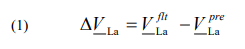
Analogously, the calculations are performed to obtain the incremental quantities for phases ‘b’ and ‘c’: ΔVLb, ΔVLc. Note that strings of both ‘flt’ and ‘pre’ fault quantities have to be of identical width and be away by integer number of the cycles. Then, the incremental positive-sequence voltage is calculated with use of the F.C. Fortescue theory [4]:Analogously, the calculations are performed to obtain the incremental quantities for phases ‘b’ and ‘c’: ΔVLb, ΔVLc. Note that strings of both ‘flt’ and ‘pre’ fault quantities have to be of identical width and be away by integer number of the cycles.
Then, the incremental positive-sequence voltage is calculated with use of the F.C. Fortescue theory [4]:
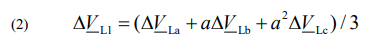
where: a=exp(j2π/3) is the complex number operator shifting by an angle: 2π/3.
Analogously, the calculations are performed to obtain the incremental positive-sequence current ΔIL1 and finally the criterion quantity for discriminating a fault direction by the relay at the L terminal is of the form [10]:
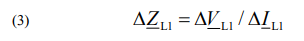
According to [10] a fault is identified as a forward one (with respect to the relay RELL) if the criterion impedance (3) is located in a 3rd quadrant of the complex plane. Adversely, in case of having this impedance located in a 1st quadrant then a fault is backward.
It is further assumed that the incremental positive-sequence voltage and current calculated for direction discrimination at the terminal L: ΔVL1, ΔIL1 and at the terminal R: ΔVR1, ΔIR1 are memorized in the relays and thus can be used for formulating a fault locating algorithm, as presented in the next section.
Fault localizing algorithm – formulation of the algorithm
Figure 2 presents a simple lumped model of a faulted power line for an incremental positive-sequence. It is assumed that phasors of voltages and currents at both local (L) and remote (R) line ends for incremental positive-sequence are calculated from the phase quantities measured asynchronously. Assuming the measurements at the remote terminal (R) as the base, then in order to provide a common time base of all measurements, the phasors at the local end (L) are multiplied by the introduced synchronization operator: exp(jδ), where δ is an unknown synchronization angle.
The model of Figure 2 can be described as follows:

where except the processed signals there are: Z1L – impedance of the whole line for the positive sequence, d – distance from the bus S to fault point F [p.u.],
By subtracting (4) and (5) one obtains the formula in which the unknown quantity ΔVF1 is eliminated and the synchronization operator equals:

Calculation of absolute values for both the sides of (6) gives elimination of the unknown synchronization angle:
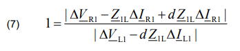
The nominator and the denominator of the right-hand term of (7) requires formulating their real and imaginary parts and then calculating their absolute values. After tedious calculations one gets a quadratic algebraic equation for the unknown fault distance (d) in the form:

where: A2, A1, A0 – real numbers involving real & imaginary parts of the positive-sequence line impedance (Z1L), real & imaginary parts of the measured phasors at the local side (ΔVL1, ΔIL1) and also from the remote side (ΔVR1, ΔIR1).
Solving the quadrating equation (8) results in obtaining two results for a sought fault distance: d1, d2. Selection of the valid solution appears not troublesome since one of the solutions can be easily rejected since it indicates that a fault is outside a protected line, what is contradictory to the decision reached by the directional elements from both line terminals. Only in very rare cases could happen that both results for a sought fault distance d1, d2 indicate a fault as within a line. In such rare cases a valid solution can be selected with considering the other symmetrical components of the measured phasors or by applying phase quantities.
Evaluation of the fault localizing algorithms
The derived fault localizing algorithm has been tested and evaluated with use of the fault signals obtained from versatile simulations of faults on the test 220 kV, 300 km double fed transmission line (Table 1). The simulation was performed using the ATPDraw software [13], while the algorithms were implemented in MATLAB.
Table 1. Parameters of the modelled transmission line
The phasors of measured currents and voltages were determined by the full-cycle Fourier filtering [4], under a sampling frequency fs=1000 Hz. The signals from the simulation are in a natural way perfectly synchronized [14]. Therefore, to adapt to the case of unsynchronized measurements considered here, the signals from the remote end (R) were analytically delayed by a half sampling period (tΔ=0.5 ms or Δ=18o in the angle domain).
Figure 3 and 4 present the example of localizing the sample fault on the test line. The specifications of the fault are: a-E fault, d=0.1 p.u., fault resistance: RF= 10 Ω. Figure 3 presents the waveforms of three-phase currents and voltages recorded at both line terminals. In turn, Figure 4 presents determination of a distance to fault with use of two methods processing the signals of Figure 3. Firstly, the localizing is performed with use of the incremental positive-sequence quantities (the derived algorithm (8)). Just for comparison purpose, additionally, the localizing was conducted by using (8), but with the positive-sequence voltages and currents taken from the fault interval (t>0.06 s).
Solving (8) for both kinds of the input signals gave two values for a distance to fault. Then, mean values of the distance were determined by averaging within the windows indicated in Figure 4.
In case of the derived method (usage of incremental positive-sequence quantities) the solution dΔ1I is rejected since it is false as indicating the fault as outside the line. In turn, the second solution dΔ1II corresponds to the real position of the applied fault. The obtained mean value is 0.1052 p.u. and thus the error (0.0052 p.u. or 0.52%) can be considered as of low value, especially when taking into account the length of the modelled line: 300 km.
In case of the second method (usage of positive-sequence quantities) again one gets two solutions and only one of them is accepted, while the second, which indicates the fault as outside the line, is rejected without a doubt. The valid solution exhibits much worse accuracy. Now the obtained mean value is 0.047 p.u. and thus the error equals 0.053 p.u. or 5.3%
The presented example (Figure 3, Figure 4) illustrates the considered two methods. More detailed analysis on accuracy of those methods is presented in Figure 5.


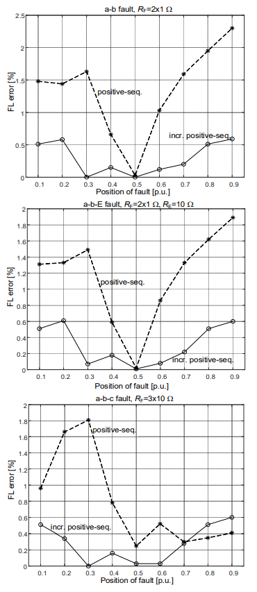
The evaluation of fault location accuracy for the tested 300 km line, presented on Figure 5, clearly indicates that the derived fault locating algorithm processing incremental positive-sequence components exhibits much superior accuracy than when using positive-sequence components taken from the fault interval only. The error for the derived algorithm is basically not exceeding 0.5%, while for the other algorithm from this comparative analysis one obtains higher values of the errors, even of the order of 10%. In case of such big errors a compensation of transmission line shunt capacitances has to incorporated obligatory.
Conclusions
This paper introduces the algorithm for localizing faults on power transmission lines for an inspection-repair purpose. Innovative input signals of the algorithm have been taken into account. Namely, incremental positive-sequence voltages and currents from directional elements of protective relays at both line ends were taken for processing aimed at determination of a sought distance to fault. For a comparison purpose also the other algorithm which processes positive-sequence quantities, but taken from a fault interval itself, has been also tested.
The derived algorithm applies practical input signals which are available in contemporary micro-processor based protective relays. Accomplishing such localizing algorithm will increase a functionality of relays.
The comparison analysis has revealed that the derived algorithm exhibits superior accuracy in comparison to the other algorithm from the comparison. The introduced algorithm can be applied even for comparatively long lines. This is important that this algorithm does not require synchronization means for the measurements acquired at both line terminals.
REFERENCES
[1] Dołęga W., Failures of overhead lines in national electric power system – selected aspects, Przegląd Elektrotechniczny, 97 (2021), nr 8, 9-14
[2] IEEE Guide for Determining Fault Location on AC Transmission and Distribution Lines IEEE Std. C37.114-2014,New York, NY, USA: IEEE, (2014)
[3] Das S., Santoso S., Gaikwad A., Patel M., Impedance-based fault location in transmission networks: Theory and application, IEEE Access, (2014), vol. 2, 537-557
[4] Saha M.M., Izykowski J., Rosolowski E., Fault Location on Power Networks, Springer, London, (2010)
[5] Gonzalez-Sanchez V.H., Torres-García V., Guillen D., Ramírez-Zavala S., Review of fault location algorithms in transmission lines, IEEE International Autumn Meeting on Power, Electronics and Computing (ROPEC), Ixtapa, Mexico, (2021), 1-8
[6] Panahi H., Zamani R., Sanaye-Pasand M., Mehrjerdi H., Advances in Transmission Network Fault Location in Modern Power Systems: Review, Outlook and Future Works, IEEE Access, (2021), vol. 9, 158599-158615
[7] Sachdev M.S., Agarwal R., A technique for estimating line fault locations from digital distance relay measurements, IEEE Transactions on Power Delivery, (1988), vol. 3, no. 1, 121-129
[8] Izykowski J., Rosolowski E., Saha M.M., A fault location method for application with current differential relays of threeterminal lines, IEEE Transactions on Power Delivery, (2007), vol. 22, no. 4, 2099-2107
[9] Avendano O., Kasztenny B., Altuve H.J., Bin Le, Fischer N.,Tutorial on fault locating embedded in line current differential relays – methods, implementation, and application considerations, 17th Annual Georgia Tech Fault and Disturbance Analysis Conference, (2014)
[10] McLaren P.G., Swift G.W., Zhang Z., A new positive sequence directional element for numerical distance relays, IEEE Transactions on Power Delivery, (1995), vol.2, 334-339
[11] Hoq T.M.D., Wang J., Taylor N., An incremental quantity based distance protection with capacitor voltage estimation for series compensated transmission lines, IEEE Access, (2021), vol. 9, 164493-164502
[12] Blumschein J.,Dzienis C., Kereit M., Directional comparison based on high-speed-distance protection using delta quantities, Siemens AG, (2014)
[13] ATPDRAW for Windows, version (7.3), Users’ Manual (2021), https://www.atpdraw.net/
[14] Stanojevic V.A., Preston G., Terzija V., Synchronised measurements based algorithm for long transmission line fault analysis, IEEE Trans. Smart Grid, (2018), vol. 9, no. 5, 4448-4457
Authors: dr Justyna Herlender, Wroclaw University of Science and Technology, Department of Electrical Power Engineering, 27 Wybrzeże Wyspiańskiego St., 50-370 Wroclaw, Poland; E-mail: justyna.herlender@pwr.edu.pl, prof. dr Jan Iżykowski, professor emeritus, IEEE fellow for contributions to fault localization on power lines.
Source & Publisher Item Identifier: PRZEGLĄD ELEKTROTECHNICZNY, ISSN 0033-2097, R. 99 NR 7/2023. doi:10.15199/48.2023.07.25
