Published by Stanisław BEDNAREK, Department of Physics and Applied Informatics, University of Łódź
Abstract. The aim of this article is to present an innovative concept, concerning the design of a photovoltaic power plant located in the stratosphere. The most important advantage of this location is the increased access to solar energy, which can be converted into electricity. The introduction of the paper presents an short overview of known locations for photovoltaic power stations – on land, at sea and in space on a geostationary orbit. The basic elements of the power station in each of these location methods along with their advantages and disadvantages are briefly discussed. The main part of the paper concerns the project of an photovoltaic power station located in the Earth’s lower stratosphere. The construction of two proposed by the author variants of such a power station with the transmission of electrical power by means of a microwave beam, or by means of a cable, is described. A maximal delivered power 20 MW of the power station has been assumed and the parameters of the elements of such power stations that are critical to their feasibility have been calculated. The feasibility of these projects with technical possibilities available currently or in nearest future has been demonstrated.
Streszczenie. Celem artykułu jest przedstawienie innowacyjnej koncepcji, dotyczącej projektu elektrowni fotowoltaicznej umieszczonej w stratosferze. Najważniejsza zaleta tej lokalizacji polega na zwiększeniu dostępu do energii słonecznej, która może być przetwarzana na energię elektryczną. We wstępnie artykułu przedstawiono w zarysie krótki przegląd znanych lokalizacji elektrowni fotowoltaicznych – na lądzie, na morzu i w kosmosie na orbicie geostacjonarnej. Krótko omówiono podstawowe elementy budowy elektrowni w każdym z tych sposobów lokalizacji oraz ich zalety i wady. Główna część artykułu dotyczy projektu elektrowni fotowoltaicznej, umieszczonej w dolnej warstwie stratosfery Ziemi. Opisano budowę zaproponowanych przez autora dwóch wariantów takiej elektrowni – z przesyłaniem mocy elektrycznej za pomocą wiązki mikrofal, albo za pomocą kabla. Przyjęto 20 MW, jako maksymalną moc dostarczaną elektrowni i obliczono parametry elementów takich elektrowni, które mają decydujące znaczenie dla ich wykonalności. Wykazano wykonalność tych projektów przy możliwościach technicznych dostępnych obecnie lub w najbliższej przyszłości. (Projekt stratosferycznej elektrowni fotowoltaiczne)
Słowa kluczowe: elektrownia fotowoltaiczna, lokalizacja, stratosfera, projekt, wykonalność.
Keywords: photovoltaic power station, location, stratosphere, project, feasibility.
Introduction
The functioning of Earth’s civilization at its current level of development requires access to various types of energy sources. The problem of ensuring continued access to these sources, or so-called “energy security,” is crucial, especially with the crisis that is currently developing. Among the many types of energy, electricity is of particular significance. This is the case for a number of reasons, including the fact that electricity can easily be converted into other types of energy, such as mechanical or thermal energy. Electricity can also be quickly transmitted over very long distances, and what is more, this kind of energy is also the least harmful to the environment where it is used, such as in cities to power electric vehicles. Of the several commonly used methods of producing electricity, generating it directly from solar energy through photovoltaic panels is highly advantageous. Large-scale photovoltaic power stations are being built to produce electricity with this method [1].
These power stations have some important advantages, including the use of a renewable and virtually inexhaustible source of energy, namely the Sun, no moving parts, low environmental impact. Photovoltaic power stations, like any other technical solution, also have their drawbacks and are therefore under constant improvement. One of these drawbacks is the conversion of only a small amount of solar energy into electricity. This disadvantage can be mitigated by locating a photovoltaic power station in a proper place. The purpose of this paper is to briefly review known photovoltaic power station locations and present an original project for an innovative stratospheric location, as well as to assess the feasibility of this concept.
Known locations of photovoltaic power stations
Photovoltaic power stations located on the ground surface have been in operation for several decades now. Their structure and project are described in detail in the literature [2]. The maximum power of the already operating or planned power stations reaches about 500 MW. The main disadvantage of the ground locations is that they allow the use of only a small portion of the energy that the Sun sends toward Earth. Power output of Es = 1.366 kW/m2 , called the solar constant [3], is sent from the Sun per area unit of the Earth’s upper atmosphere. Due to absorption and scattering in the Earth’s atmosphere, the ground surface is reached by the power of about 200 W/m2 on average. This power depends on a multitude of factors, including cloud cover for a given time of day and year or latitude. To obtain a large output of such a power station, it is necessary to have a sufficiently large area of land occupied by photovoltaic panels and to choose a location with strong insulation. These, too, are disadvantages of power stations in such a location, as the case in many situations is the shortage of land suitable for such structures [4].
A way to partially get rid of the mentioned disadvantages is to locate a photovoltaic power station on sea surface. It is widely known that seas and oceans occupy 70.8% of the Earth’s surface, so choosing the right location may be easier. A schematic diagram of the construction of a photovoltaic power station on sea surface and an explanation of its operational principle is shown in Fig. 1.

Such a power station is similar in structure to a power station located on the ground, and its operational principle is also alike. The main difference is that the photovoltaic panels are placed on floats, rather than on brackets attached to foundations, as in the case of a power station located on the ground. Prototype photovoltaic power stations intended for the sea surface are already in operation, including off the coasts of the Netherlands and Norway [2]. Unfortunately, they still have the main, disadvantage of making little use of the energy sent by the Sun. In addition, new problems arise with such a power station, such as the protection of structural components from sea waves or the damaging effects of seawater.
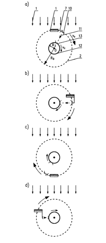
A radical way to increase the amount of available energy from the Sun is to locate a photovoltaic power station above the upper layers of the Earth’s atmosphere. Such a power station would be an artificial satellite of Earth on a geostationary orbit [5]. A characteristic property of a geostationary satellite is that it moves at the same angular velocity as the Earth rotates around its axis [6]. This ensures that the geostationary satellite is constantly over the same point on the Earth’s surface. The concept of building a photovoltaic power station on the geostationary orbit is not new. This idea was proposed in 1967 by Glaser, who also developed a way to transmit electricity to the Earth’s surface using microwaves and a system of antennas [7]. A schematic diagram of the construction of an orbital photovoltaic power station and a brief explanation of its operational principle is shown in Fig. 2 and 3 [5].
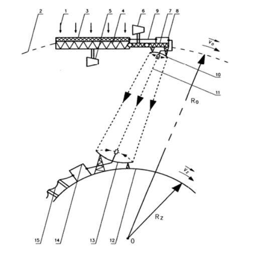
By changing the direction of photovoltaic panels, this type of a power station can use the energy sent by the Sun almost around the clock. This possibility is explained in Figs. 2 and 3. Direction of photovoltaic panels 3 is changed by means of small thrusters (marked as 5, 6 in Fig. 2), so-called correction motors. In addition, the shape of the arm with joints 7, on which the transmitting mirror 10 is placed, is also changed, for example, by means of actuators. This ensures that the microwave beam 11 always hits the receiving mirror 13, located on the Earth’s surface 12.
The radius of the geostationary orbit, located in the equator plane is about 42170 km. Such a distance from Earth features are extremely harsh physical conditions as well as exposure to cosmic radiation and meteors. The cost of transporting 1 kg into space ranges from $ 4 000 to $ 20 000 [8]. The mass of cargo that a rocket can carry into the orbit during a single launch is limited to a maximum of several dozens of tons. For these reasons, among others, building an orbital photovoltaic power station is an extremely difficult and expensive technical undertaking. With the development of aerospace, the project for such a power station has been revisited several times [9]. Enterprises were even created to handle its implementation and deadlines were set for the start of operations. Despite this, the orbital photovoltaic power station project has not yet been undertaken and completed [10, 11].
Stratospheric photovoltaic power station
The enormous difficulties of building an orbital power station can be eliminated and its primary advantage, that is, the high use of solar energy, can be preserved. For this purpose, the photovoltaic power station should be placed in the stratosphere. The stratosphere is located at an altitude of 20-40 km above the Earth’s surface. It is a layer with a low air pressure of 55-2.9 hPa, above the upper limit of clouds [8]. No winds blow and no weather phenomena occur there. Passenger planes and other aircrafts do not fly in this altitude range, only some types of military airplanes can be encountered there on rare occasions. Therefore, a photovoltaic power station in the stratosphere would be safe for air traffic. The more outer layers of the atmosphere contain even less air, so they absorb little of the Sun’s energy, hence the power of about 1 kW/m2 reaches the stratosphere. Structural schematics of a photovoltaic power station, located in the stratosphere, are shown in Figs 4 and 5.
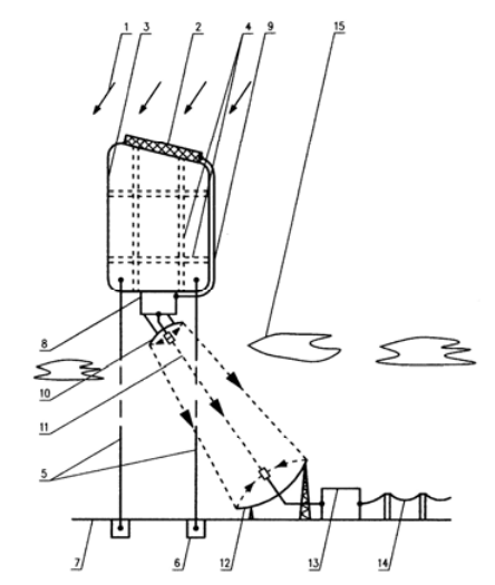
The construction and operation of such a power station would be partly similar to that of an orbital power station. The main difference is that due to the air content in the stratosphere, it is possible to use the buoyancy force and place photovoltaic panels 2 on stratospheric balloons 3 that float them. The balloons would be filled with gas with a density lower than that of atmospheric air, preferably helium [13]. (In the case of an orbital power station, movement on a geostationary orbit is made possible by balancing the gravitational pull by the centrifugal force.) The movement of stratospheric balloons will be restricted with ropes 8 or 5, the lower ends of which are fixed to the ground 7. On the inside, non-stretchable belts 4 are attached to the shell of the balloons. The job of these belts is to make the balloons as flat as possible, more favorable for placing photovoltaic panels on them. The relatively low altitude of the lower stratospheric boundary allows to consider the possibility of transmitting electricity to the Earth’s surface also by means of a power cable 11 (Fig. 5). The stresses in the ropes and cable can be reduced by placing displacement cylinders 12 on them, acting in the same way as balloons. In further calculations, it will be shown that when those ropes and cable insulation are made from the right material, such cylinders are not necessary. The following part of the paper includes calculations of parameters that are fundamental to the feasibility of both variants of stratospheric photovoltaic power stations.

Parameters of a power station with microwave energy transmission
First, calculations will be carried out for a power station from which the electricity produced is transmitted to the Earth’s surface using a microwave beam (Fig. 4). The efficiency of the transmission of electricity to the Earth’s surface by means of microwaves in systems known from the literature and tested for photovoltaic power plants is high, at more than 80% [14].The following values of output parameters are assumed for the calculations: maximal power delivered to surface of the Earth Pd = 20 MW, total coefficient of power delivering ηd = 0.8, From results that maximal power produced by the all photovoltaic panels amounts of Pe = 25 MW. Are assumed also the others parameters as following: height over the Earth’s surface h = 20 km, power of one panel Pp = 100 W, panel dimensions – length l = 1 m, width w = 0.5 m, maximum voltage at the output of the panel Um = 20 V, maximum current at the output of the panel Im = 5 A, mass of one panel m1 = 0.2 kg. It was assumed that thin-film panels would be used, made of perovskite with a film printing technique [15, 16]. Such panels are currently being intensively researched and may be commercially available in the near future. Photovoltaic films are already being tested, stuck on the walls of buildings [17]. This will keep the weight of the panel low and achieve high efficiency η = 20% [18, 19]. In addition, the panels in the stratosphere do not need to be protected from weather conditions including hail or snow, so there is no need for shielding and thus their weight can be low. However in the stratosphere such panels may require additional protection with a film that absorbs intense UV radiation. The estimation of mass of a 0.2 kg per panel is made on the basis of the density and quantities of the materials used to its manufacture. Using these data and standard formulas to project photovoltaic power stations, the following were calculated: the number of panels Np = 2.5×10⁵ , their total area Sp = 1.25×10⁵ m2 = 12.5 ha, and the total mass mp = 5×10⁴ kg = 50 t. It was assumed that the panels would be distributed over an area of a square of side ab, and hence ab = 353.6 m was obtained. In addition, it was assumed that the component block 8, converting DC energy into microwave energy, (containing, among other things, an inverter and magnetron), the connection cable of the conversion block 9, the transmitting mirror 10 and the cables connecting the photovoltaic panels would have a total mass of me = 6 t. The stratospheric balloon 3 must be equipped with at least one rope 5 limiting its movement, which will also act as a load. To reach the appropriate strength, it is assumed that the rope, having a mass of ml , will be made of Kevlar (a type of polyamide), whose tensile strength σk = 36×108 N/m2 , while the density ρk = 1430 kg/m3 [3]. The tension of a freely hanging rope with length lk, diameter dl, made of this material, which will break at the point of attachment under its own weight is expressed by the formula
Symbol g in formula (1) stands for the gravitational acceleration. The average value of g at the Earth’s surface is 9.8065 m/s2 . It follows from equation (1) that lk does not depend on the diameter of the rope dl, and after transformation is expressed by the formula
After substituting the values adopted from formula (2), lk = 251.2 km is obtained. Thus, a rope with a length of h = 20 km will not break. So there will be no need for displacement cylinders 12. Using equation (1), we can also calculate the mass of a rope mk with length h. Assuming a rope diameter of dl = 10 mm, ml = 2.3 t is obtained. The rope can still be affected by an force of aerodynamic resistance directed approximately horizontally and caused by the wind. Assuming a maximum wind speed of 120 km/h and using the basic formulae for aerodynamic force during cylinder flow, the value of this force was estimated to be 2.1×10⁴ N [20]. Based on this result, the strength calculations were repeated and dl = 14 mm and ml = 4.5 t were obtained and this mass value will be used for further calculations.
The calculations show that the stratospheric balloon will be loaded with the sum of the masses mp, me and ml ,amounting to 60.5 t. To maintain this mass in the stratosphere, the balloon must be large enough. Let the balloon have an approximate cuboid shape with a square base. The side of this base has a previously calculated length ab = 353.6 m. For this length ab the necessary height of the balloon hb will be calculated. The condition for a balloon to remain in equilibrium is the equality of its total weight Wc and the buoyancy force Fw, which is exerted on it by the air in the stratosphere, which has a density of ρa. Therefore
The symbol ge in formula (4) stands for the gravitational acceleration at the height h at which the balloon is placed. In addition to the weights resulting from the loading with the masses by the sum of the masses mp, me and ml, the total weight of the balloon Wc is made up of the weight of its shell Wb of thickness t, made of material of density ρp, and the weight of the helium Wh contained in this shell, whose density at height h is ρh. According to these designations, the following formulas can be composed
After using equations (3), (4) and the assumptions made, the following equation can be composed
from which, after transformation, the following formula for the height of the balloon hb is obtained.
The coatings of stratospheric balloons are usually made of high-density polyethylene ρp = 960 kg/m2 (so-called HD polyethylene) and have a thickness t within a few tenths of a mm [9]. A coating thickness of t = 0.25 mm was assumed. At altitude h, the density of air in the stratosphere ρa = 0.0898 kg/m3 , while temperature ta = – 55ºC [3]. In turn, under normal conditions (tn = 20°C and pn = 101325 N/m2 ), the density of helium ρn = 0.164 kg/m3 . For the balloon’s shell to remain in equilibrium, the helium pressure inside the balloon should be equal to the atmospheric pressure at altitude h, i.e. pa = 5500 N/m2 . Both the atmospheric air and helium satisfy the equation of state of a perfect gas under the conditions considered, and therefore the density of helium ρh at altitude can be applied using the equation of state of a perfect gas, from which the formula is obtained
symbols Tn and Ta in formula (9) denote the temperatures tn and ta, respectively, expressed on the Kelvin scale (Tn = 293 K and Ta. = 218 K). After substituting the previously given values into equation (9), one gets ρh = 0.0120 kg/m3 . In this way, the values of all the quantities needed to determine the height of the balloon hb were obtained. Substituting these values into equation (8) yields hb = 11.47 m. Using this value and the previously given formulas and quantities, it is also possible to calculate the volume of the balloon Vb = 1,43×10⁶ m3 , the mass of the balloon shell mb = 50,5 t and the mass of the helium contained in it mh = 17.2 t.
Parameters of a power station with energy transmission through a cable
To ensure power transmission through a cable with the smallest possible cross-sectional area Sk, reduce the power loss ΔP and reduce the mass of the cable mk, the current at the output of the panel system must be reduced. The number of all panels calculated beforehand is Np = 20×105 . Let the panels be connected in a mixed way, i.e. series-parallel into assemblies. The number of these units connected in parallel is 20, and each unit has 104 panels connected in series. Each of the selected panels gives a maximum voltage of 20 V at the output and a maximum current of 5 A. Therefore, from all Np panels a maximum voltage Ue = 200 kV and a maximum current Ie = 100 A is obtained. To transmit this current, a wire with a cross section Sm = 50 mm2 made of copper with resistivity ρm = 0.171×10⁻⁷Ωm will be used. The resistance of a two-core cable with length h = 20 km, with such conductors is ΔR = 6.84 Ω. The voltage drop on the cable ΔU = 684 V, and the power loss ΔP = 68.4 kW, which is 0.34% of the maximum power of the power station. Since the power loss during transmission over the cable is small, this can be ignored. Then the maximum power produced by all photovoltaic panels is also 20 MW. For this purpose, Np = 2×10⁵ panels are needed, with a total area Sp = 105 m2 = 10 ha and a total mass mp = 4×10⁴ kg = 40 t, which will be arranged in a square with side ab = 316.2 m. The density of copper ρm1 = 8.95×10³ kg/m3, and its breaking strength σm = 2×10⁸ N/m2 . The mass of copper wires in a cable of this length is mm = 17.6 t. Applying equation (2) for copper allows to conclude that a free-hanging cable made of copper will break under its own weight already at a length of 2.28 km. For this reason, it is necessary to strengthen the cable. This can be achieved by using a layer surrounding the wires with a sufficiently large cross-sectional area Sk, made of a material more resistant to tearing. This material will be Kevlar, and its layer adjacent to the wires will also act as insulation. For such a cable, which is a system of two composite materials, the resultant breaking strength σw is expressed by the following formula, derived from the Hooke’s law [21]
If we assume that each copper wire has a cross-sectional area in the shape of a semicircle, the wires are facing each other with their flat sides, and the thickness of the surrounding Kevlar insulation layer will be 6 mm, then the cross-sectional area of the insulation made of this material Sk = 6.45 cm2 . When this value and the previously assumed material parameters are substituted into equation (10), σw = 31.44×10⁸ N/m2 is obtained. Further calculations using basic formulas show that the insulation on such a cable of length h will have a mass of mi = 18.8 t. The sum of the masses of mm and mi, or the total mass of the cable mk = 36.4 t. The maximum stress of such a cable at the point of suspension is 6.15×10⁸ N/m2 , which is less than σw, so a cable of length h will not break under its own weight. As before, force of the aerodynamic resistance acting on the cable was estimated as 6.3×10⁴ N, Once this force was accepted into calculation the mass of the cable mk = 43 t. To calculate the balloon’s hb height, repeat the calculation according to equation (8) after replacing me with mk. Then hb = 16.71 m is obtained. The other parameters of the balloon of this height were calculated as before and the following were obtained: balloon volume Vb = 1.67×10⁶ m3 , shell mass mb = 56.8 t and mass of helium contained in it mh = 20.1 t.
Conclusions and summary
Calculations have shown that a photovoltaic power station, consisting of panels and other energy transfer components, can be maintained in the stratosphere at an altitude of 20 km above the Earth’s surface using a helium filled balloon. A suitable balloon shape for this purpose is a cuboid with a square base. Photovoltaic panels would be placed at an optimal angle on the top surface of this balloon and possibly on its side surfaces facing the direction of solar radiation. If the maximum delivered power of the power station is 20 MW, the side of the square base of the balloon should be in the range 316.2-353.6 meters long, and the height of the balloon should be in the range of 11.47-16.71 meters. These results are comparable to the dimensions of built stratospheric balloons. For example, the Felix Baumgaretner balloon built in 2017 year had a diameter of 129 meters, a height of 102 meters and a shell made of high-density polyethylene equal to 0.1 mm thick [22, 23]. Adopting twice the thickness of the balloon’s shell for the calculations carried out is intended to ensure greater durability of the balloon, since helium in the gaseous state has a high ability to penetrate various materials. Of course, one can also consider the project of a stratospheric photovoltaic power station with a smaller power, for which the dimensions of the balloon will be respectively smaller.
The calculated height of the balloon depends on how the electricity is transmitted to the Earth’s surface. Two methods can be used for this purpose. The first way involves converting electrical energy into microwave beam energy using components suspended from the balloon. The microwaves will then be received by a terrestrial antenna and converted into electricity, sent to the power grid. The second way involves transmitting electricity to the Earth’s surface using a cable suspended from a balloon. Afterwards, the energy received on the Earth’s surface will be transmitted to the power grid. Calculations have shown that with the selection of suitable cable materials, the second way is also feasible. Despite that fact, the first way will be more advantageous, due to the lower volume of the balloon and the lower mass of helium needed to fill it.
The efficiency of photovoltaic panels was assumed to be 20% for the calculations, but intensive research is underway to use new materials for these panels. These materials provide for greater efficiency and lower panel manufacturing costs [24]. As a result, the necessary area of the panels, the size of the balloon and the cost of building the power station will be smaller, which will increase the investment profitability. Due to the limited volume of the paper, the calculations carried out are of a simplified nature and concern only parameters critical to project feasibility. However, for the comparison it will be added that, operating an average of 12 hours a day, such a power station could supply 87.6 GWh of electricity to the grid in 1 year. A power station on the Earth’s surface with the same power could deliver 18.9 GWh. This is 4.6 times less [25].
Table 1 Advantages and disadvantages of different photovoltaic power station locations

A comparison of the advantages and disadvantages of locating a photovoltaic power station in the stratosphere with other locations is given in Table 1. A stratospheric photovoltaic power station would have significant advantages, such as high utilization of solar energy, resistance to atmospheric factors (cloud cover, snowfall, dust contamination of panels), much lower construction and operating costs compared to an orbital power station and would not occupy scarce land area. Therefore, the project of such a power station seems interesting and should be the subject of more thorough studies of its feasibility and profitability. This statement is all the more justified because the current energy crisis calls for the search for new ways to obtain electricity, especially from renewable sources.
It is worth mentioning that the power provided by the proposed power station can be increased if the photovoltaic panels are also placed on the sides of the balloon, or the balloon has a different shape, such as a sphere or hemisphere covered with panels. This option requires further analysis and more complex calculations. Another solution is to build a power station composed of a number of balloons of smaller size described, a so-called farm. On each of these balloons will be installed a set of panels with a smaller power output than the power assumed for the calculations. However, the total power obtained from such a farm will be greater than that assumed in this article. Such a farm will also show greater reliability and better adaptation of the amount of electricity produced to variable demand.
It should also be noted that despite the technical feasibility and profitability of building such a power station, this project may not be implemented. This will be the case since the political and ideological factors also have a decisive influence on the implementation of innovative solutions. There are many examples of this influence, such as the fact that plans to build a nuclear power station in Poland were postponed for more than 40 years.
REFERENCES
[1] Sibiński M., Znajdek K., Przyrządy i instalacje fotowoltaiczne, Wydawnictwo Naukowe PWN, Warszawa (2022), s. 72
[2] Cisse A.A., Diallo M.S., Przewidywanie mocy elektrowni fotowoltaicznej, Wydawnictwo Nasza Wiedza, Warszawa (2021), s. 28
[3] Mizerski W., Tablice fizyczno-astronomiczne, Wydawnictwo Adamantan, Warszawa (2013), s. 392
[4] Wasa M., Pierwsza w Polsce farma PV o mocy 1 MW, Magazyn Fotowoltaika, 3 (2011) 12
[5] Introduction of Research: About the SSPS, https:// http://www.kenkai.jaxa.jp/eng/research/ssps/ssps-ssps.html (2022) [dostęp: 8.01.2023]
[6] Bednarek S., Rola fotowoltaicznych elektrowni orbitalnych w zapewnieniu globalnego bezpieczeństwa energetycznego, w: Gałecki A., Bolewski A. (red.), Bezpieczeństwo – wielorakie perspektywy, Bezpieczeństwo energetyczne wyzwaniem XXI wieku, Wydawnictwo Wyższej Szkoły Bezpieczeństwa w Poznaniu (2017), 25-36
[7] Glaser P.E, Power from the Sun: Its Future, Science, 162 (1968) n. 3856, 857-861
[8] Izet-Unsalan K, Unsalan D., A low cost alternative for satellites- tethered ultra-high altitude balloons, Proceedings of 5th International Conference on Recent Advances in Space Technologies – RAST2011, Edited by ieeexplore.ieee.org, (2011), 13–16
[9] Nagatomo M., Sasaki S., Naruo Y., Conceptual Study of A Solar Power Satellite SPS 2000, Proceedings of the 19th International Symposium on Space Technology and Science, Paper No. ISTS-94-e-0, (1994) Yokohama, Japan, p. 469-476
[10] European Space Agency eyes making expensive solaris based solar power, Science Times, 20 August (2022)
[11] China to build space-based solar power station by 2035, http://www.xinhuanet.com (2019) [dostęp: 8.01.2023]
[12] Szczeciński S., Ilustrowany leksykon lotniczy, Wydawnictwa Komunikacji i Łączności, Warszawa (1988), s. 127
[13] Jankiewicz Z., Aerostaty. Balony i sterowce, Wydawnictwo Ministerstwa Obrony Narodowej, Warszawa (1982), s. 38
[14] Sasaki S., Tanaka K., Maki K., Microwave Power Transmission Technologies for Solar Power Satellites, Proceedings of the IEEE, 101 (2013), 1438
[15] Manser J.S., Christians J.A., Kamat P.V., Intriguing Optoelectronic Properties of Metal Halide Perovskites, Chemical Reviews, 116, (2016), n. 21, 12956-13008
[16] Dajlel D., Materiały cienkowarstwowe do zastosowań fotowoltaicznych, Wydawnictwo Nasza Wiedza, Warszawa (2021), s. 45
[17] Folie fotowoltaiczne na elewacji Ekospalarni, https://www.sozosfera.pl/zielona-energia/folie-fotowoltaiczne-na-elewacjiekospalarni/ (2021) [dostęp: 8.01.2023]
[18] Kojami A. et. al., Organometal Halide Perovskites as VisibleLight Sensitizers for Photovoltaic Cells, Journal of the American Chemical Society, 131, (2009), n. 17, 6050-6051
[19] Sun K. et. al., Short-Term Stability of Perovskite Solar Cells Affected by In Situ Interface Modification, Solar RRL, 3 (2009), n. 9, 1900089
[20] Szczeniowski S., Fizyka doświadczalna, część I, mechanika i akustyka, Państwowe Wydawnictwo Naukowe, Warszawa (1972), s. 487
[21] Niezgodziński M.E., Niezgodziński T., Wytrzymałość materiałów, Państwowe Wydawnictwo Naukowe, Warszawa (1997), s. 148
[22] http://www.wired.com/2012/10/red-bull-stratos-balloon/ [dostęp: 7.01.2023]
[23] Bellemare M.G., Candido S., Castro P.S., Gong J., Machado M.C., Mitra S., Ponda S.S., Wang Z., Autonomous navigation of stratospheric balloons using reinforcement learning, Nature, 588 (2020), 77-82
[24] Massiot J., Cattoni A. Collin S., Progress and prospects for ultrathin solar cells. Nature Energy, 5 (2020), n. 12, 959–972
[25] Topolski J., Projekt budowlany elektrowni fotowoltaicznej w gminie Szypliszki, PPTJ Topolski, Kolesin (2013)
Author: dr hab. inż. Stanisław Bednarek, Department of Physics and Applied Informatics, University of Łódź, 149/153 Pomorska Str., 90-236 Łódź. E-mail: stanislaw.bednarek@uni.lodz.pl.
Source & Publisher Item Identifier: PRZEGLĄD ELEKTROTECHNICZNY, ISSN 0033-2097, R. 99 NR 7/2023. doi:10.15199/48.2023.07.37
