Published by 1. Damian KOSTYŁA1, 2. Paweł WĘGIEREK1, 3. Michał LECH1,
Lublin University of Technology, Faculty of Electrical Engineering and Computer Science (1)
ORCID: 1. 0000-0002-9012-0158; 2. 0000-0002-0812-3414; 3. 0000-0002-4732-2459
Abstract. The paper presents a review of traditional and fiber optic methods dedicated to pressure measurement in the context of ongoing research work on the development of a fiber optic sensor designed to measure pressure values in vacuum extinguishing chambers used in modern switchgear, allowing real-time monitoring.
Streszczenie. W artykule przedstawiono przegląd tradycyjnych oraz światłowodowych metod dedykowanych do pomiaru ciśnienia w kontekście prowadzonych prac badawczych, dotyczących opracowania światłowodowego czujnika przeznaczonego do pomiaru wartości ciśnienia w próżniowych komorach gaszeniowych stosowanych w nowoczesnej aparaturze łączeniowej, umożliwiającego prowadzenie monitoringu w czasie rzeczywistym. (Technika światłowodowa do pomiaru ciśnienia w wysokonapięciowej aparaturze łączeniowej)
Słowa kluczowe: diagnostyka próżni, wytrzymałość dielektryczna, technika światłowodowa, światłowodowe czujniki ciśnienia.
Keywords: vacuum diagnostics, dielectric strength, fiber optics technology, fiber optic pressure sensors.
Introduction
The popularity of the Smart Grid concept [1], monitoring of as many network parameters as possible as well as increasingly restrictive environmental regulations [2] and the growing importance of closed-circuit equipment force distribution system operators to use a new efficient and, above all, ecological insulating medium with parameters at least equivalent to those of sulphur hexafluoride [3-4], i.e., vacuum. A gas with very good insulating properties, which is also inert for the environment which is an important advantage. Currently, however, there is no solution for measuring the pressure value in vacuum extinguishing chambers used in high-voltage switchgear.
From a safety point of view, pressure measurement is extremely important because a vacuum can only retain good insulating properties once a certain pressure value has been reached, which leads to the problem of controlling the pressure state in vacuum equipment [5].
Acceptance tests to which manufacturers of vacuum chambers are obliged [6], as well as periodic inspections of the technical condition of vacuum devices, despite their low susceptibility to leakage [7], can be insufficient, as they do not provide information on whether, and if so when, the tested chambers will leak and lose their insulating properties.
This is a particularly dangerous situation for the health and lives of people carrying out maintenance work on electricity networks and equipment in which vacuum insulated equipment is used.
Dielectric strength of vacuum
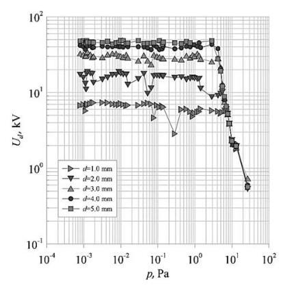
The overriding aspect affecting the dielectric strength of vacuum devices is the pressure prevailing in the apparatus. Research has shown that for pressures lower than 10-2 Pa [8-9], the dielectric strength of vacuum apparatus is high and stable, which means that its changes are negligible and depend only on the inter-tap distance. The biggest problem in the use of vacuum becomes apparent when the pressure in the apparatus rises above 1 Pa. This is when the strength of the vacuum drops dramatically [5] as shown in Figure 1.. This is when the vacuum strength drops dramatically. It is therefore important to check the pressure of the apparatus on a regular basis, preferably on-line, in order to reduce the risk of leaving unsealed apparatus with inadequate insulation parameters in service.
The main problem with gas-insulated apparatus is that it is not possible to visually check for leakage, as this requires the use of appropriate measuring techniques and specialized equipment.
Therefore, pressure measurement in the vacuum apparatus remains extremely important.
Measurement of pressure in vacuum apparatus
To meet safety aspects, many methods have been developed to measure pressure in vacuum equipment. Pressure diagnosis methods have been the subject of research by many scientists for a long time [9].
The key aspect of measuring the pressure in the apparatus is to determine the unsealing of the device, i.e. the increase in pressure above 100 Pa, which causes the loss of insulating properties of the extinguishing chamber. As can be seen from Table 1, there are methods which make it possible to determine the pressure prevailing in a vacuum apparatus, but their use requires either specialized equipment or disassembly of the chamber and testing in a laboratory, which results in many unfavorable circumstances, e.g. an increase in reliability coefficients or the need to incur considerable financial outlays, necessary for purchase of appropriate measuring equipment.
Table 1. Summary of traditional vacuum chamber diagnostic methods [9].
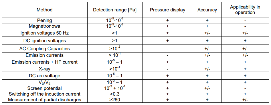
The problem of conventional methods is also the low accuracy of measurements. As a matter of fact, it can be read from the table that some of the presented methods enable pressure measurement with satisfactory accuracy, however, they are connected with the necessity of making modifications to the operating device. Thus, for the AC ignition voltage measurement it is necessary to adjust the inter-tap distance in order to detect the prevailing pressure [10], and for the high-frequency current surge emission measurement method [11] it is necessary to induce a high-frequency direct current discharge, which, in spite of the possibility of measuring directly in the device, causes the necessity of shutting down the device for testing, and this, in turn, influences the increase in the reliability coefficient values. A recently recognized method is the measurement of partial discharges [12], however the measurement range offered by this method is insufficient, and the development of a system for which the partial discharge will take place only inside the discharge chamber requires complicated isolation processes.
Due to the continuing interest in vacuum technology, it is becoming necessary to develop new innovative methods that allow real-time measurements to be made without interfering with the operation of the vacuum device itself.
Researchers have therefore shifted their research interests towards fiber optic technology.
Fiber optic technology for pressure measurements in high voltage vacuum apparatus
With their small size, low weight, high level of sensitivity, resistance to corrosion and, most importantly, resistance to electromagnetic interference, fiber optic sensors are an alternative to conventional measurement methods [13-14]. The above advantages have intensified the interest of researchers, as evidenced by the amount of research aimed at popularizing and industrializing fiber optic sensors in various configurations such as the Fabry-Perot (FPI) sensor [15], Bragg grating sensors [16], polymer grating Bragg sensor [17] and other fiber optic sensor structures [18-20].
The multitasking nature of fiber optic sensors also causes problems. The susceptibility of fiber optics to temperature is ideally suited to the idea of building a fiber optic temperature sensor, but in pressure measurements this poses a major problem. It is therefore necessary to use appropriate techniques to compensate for the influence of temperature [14].
The problem of temperature compensation for fiber optic pressure sensors is the subject of research work. Various methods have been developed to compensate for the effects of temperature on sensor operation. Some of them are based on the use of two optical fibers. The first one is subjected to the influence of both pressure and temperature, while the second one is only affected by temperature, which, based on the difference in wavelength, allows the influence of temperature on the obtained results to be determined [21]. An alternative version of temperature influence compensation is the use of two Bragg gratings, but connected together in a structure [22], which, when the same temperature acts on each of the gratings, causes the same deformation for both gratings, but with opposite values, which allows compensation of the temperature influence during measurements.
An additional complication when conducting measurements with replaceable fiber optic sensors is the measurement system itself. When using optical elements, an optical spectrum analyzer, which is an excellent measuring device for laboratory use, is necessary for reading the results. The situation looks much worse when making measurements in real power plants. The optical spectrum analyzer is not very compact, which makes it practically impossible to carry out measurements in the field. In addition, it should be noted that the purchase of an analyzer is associated with a significant financial outlay that must be borne.
Research methodology
Despite the existence of many pressure measurement methods as well as fiber optic sensor configurations, to the authors’ knowledge, there is no known solution to control the pressure level in vacuum apparatus in real time. This poses the technological challenge of developing a system to monitor pressure values in vacuum quench chambers used in high voltage switching apparatus.
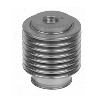
A key solution used in the innovative on-line pressure monitoring system are elastic bellows, which act as an element transferring mechanical stress caused by the vacuum present in the chamber. The innovation in the use of this type of material lies in the measurement of low pressure, as opposed to traditional applications where overpressures of the order of MPa are measured.
The technological challenge is the non-linearity of the bellows operation with respect to the applied pressure and its installation method in the experimental setup. Bellows made of bronze and metal, stainless steel and nickel and copper will be used in the test work. Testing of bellows made from different materials is aimed at finding the bellows with the highest deformation due to pressure loading in order to maximize the measurement range. An example of a bellows used in this study is shown in Figure 2. The most important parameters of this bellows are an elasticity of 8.3 N/mm, a maximum deflection of at least 4.5 mm and a maximum operating pressure of 106 Pa.
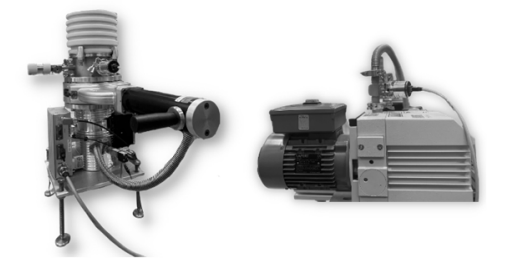
Specialized testing at pressures in the range of typical vacuum chamber operation, i.e., from 10-3 Pa to 10-2 Pa, would not be possible without a set of vacuum pumps, as shown in Figure 3, capable of reaching pressures of 10-4 Pa. In order to reach the pressure required for the tests, a rotary pump is activated as a pre-pump. After it reaches a pressure of 6*102 Pa, the second pump, a turbomolecular pump, is activated, enabling the pressure of 10-4 Pa to be reached, a value which is completely sufficient in the context of the research being carried out, the main objective of which is to develop a method for detecting, above all, unsealing of the vacuum system, i.e., a rise in pressure above 100 Pa.
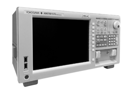
The principle of operation of the system under development is as follows: under the influence of the applied pressure, the bellows is deformed, which, in combination with an optical Bragg grating, makes it possible to measure this deformation, which is correlated with the pressure prevailing in the system. For the purposes of laboratory work, an optical spectrum analyzer, shown in Figure 4, is used to detect bellows deformation, and thus the shift in the optical Bragg grating spectrum. It is characterized by a high dynamic range of measurements exceeding 55 dB, with an attenuation coefficient of over 70 dB. The spectral range offered by the equipment in use is between 600 nm and 1620 nm. Within the framework of conducted research works, it is planned to develop an optoelectronic crosstalk system, which will be a faster, easier to operate and more economically advantageous alternative for measurements performed with an analyzer.
Pressure tests are only part of the research work to which the measuring system under development is subjected, as the important issue is the behaviors of the system in real operating conditions.
In order to carry out voltage tests of the sensor, a dismountable vacuum chamber, shown in Figure 5, is used. After mounting the tested sensor in it, it is possible to verify empirically the correctness of its operation both in the normal state and in the fault condition. What is important, the specialized design of the chamber makes it possible to change the configuration of the device by mounting additional components in place of the glass sight glass. The installation of additional apparatus in the chamber requires the use of vacuum grommets ensuring the tightness of the system.
Summary
The development of a fiber-optic system for monitoring pressure values in vacuum quench chambers, enabling real-time measurement, ideally fits into the idea of a Smart Grid, as well as being a response to development trends and the needs of the utility power industry.
The final version of the metering system will be used in modern switchgear and distribution equipment, as well as in innovative medium-voltage cable connectors equipped with vacuum circuit breakers and switches.
The application of the system in question will significantly improve the reliability coefficients by reducing the number of interruptions in the supply of electricity to end customers, both planned, caused, among others, by periodic inspections of equipment, and unplanned, caused by equipment failures. In addition, it will have a positive impact on increasing the safety of maintenance work on power equipment.
This work was supported by The National Centre for Research and Development and co-financed from the European Union funds under the Smart Growth Operational Programme (grant # POIR.01.01.01-00-0451/21)
REFERENCES
[1] Węgierek P., Staszak S., Pastuszak J., EKTOS – innovative medium voltage outdoor vacuum disconnector in a closed housing dedicated to the network Smart Grids, Wiadomości Elektrotechniczne 2019, R87, nr 11, p.21-25,
[2] Rusek T., Gospodarka SF6 w instalacjach elektroenergetycznych – wybrane aspekty prawne, Przegląd Elektrotechniczny 2014, vol. 2-3, p.41-56,
[3] Smeets R, van der Sluis L, Kapetanović M, Peelo DF, Janssen A. Switching in electrical transmission and distribution systems. 1st ed. West Sussex: John Wiley & Sons Ltd; 2015.,
[4] Hiroki I. Switching equipment. 1st ed. Cham: Springer; 2019
[5] Węgierek P., Lech M., Kostyła D., Kozak C., Study on the Effect of Helium on the Dielectric Strength of Medium-VoltageVacuum Interrupters, Energies 2021, 14, 3742. https://doi.org/10.3390/en14133742
[6] PN-EN 62271-1 Wysokonapięciowa aparatura rozdzielcza i sterownicza – Część 1: Postanowienia wspólne
[7] Razi-Kazemi A.A., Fallah M.R., Investigation of aging procedure of vacuum circuit breakers used in wind farms, Engineering Failure Analysis, Volume 123, 2021, 105292, https://doi.org/10.1016/j.engfailanal.2021.105292.
[8] Bang, S.; Lee, H.-W.; Lee,B.-W. Real-Time Monitoring of the Vacuum Degree Based on the Partial Discharge and an Insulation Supplement Design for a Distribution Class Vacuum Interrupter. Energies 2021, 14, 7891. https://doi.org/10.3390/en14237891
[9] Chmielak W. Review of methods of diagnostics of the vacuum in vacuum circuit breakers, Przegląd Elektrotechniczny, 90(2), 213–16, (2014). https://doi.org/10.12915/pe.2014.02.54
[10] Damstra G. C. Pressure Estimation in Vacuum Circuit Breakers IEEE ‘Trans. on Dielectrics and Electrical Insulation Vol. 2 No.2, April 1995
[11] Frontzek F.R, Konig D., Measurement of Emission Currents Immediately After Arc Polishing of Contacts IEEE Trans. on EI, vol. 28,No. 4, 1993, p. 700-705
[12] Yang, D.; Zhang, W.; Xu, G.; Li, T.; Shen, J.; Yue, Y.; Li, S. Partial Discharge Pulse Segmentation Approach of Converter Transformers Based on Higher Order Cumulant. Energies 2022, 15, 415. https://doi.org/10.3390/en15020415
[13] Xiaofei Y., Jianhua W., Shaogui A., Zhiyuan L., Yingsan G., Zhiguo H., Vacuum Switching Technology for Future of Power Systems, Engineering, 2022, https://doi.org/10.1016/j.eng.2021.11.020.
[14] Qinggeng Q., Zhen’an J., Dequan F., Zhen Y., Highly sensitive FBG pressure sensor based on square diaphragm, Optic, Vol. 225, January 2021, https://doi.org/10.1016/j.ijleo.2020.165559
[15] Wu C., Fu H., Qureshi K.K., Guan B.-O., Tam H.-Y., Highpressure and high-temperature characteristics of a Fabry–Perot interferometer based on photonic crystal fiber, Opt. Lett. 36 (2011) 412–414.
[16] Vorathin E., Hafizi Z., Aizzuddin A., Zaini M.K.A., Lim K.S., A novel temperature-insensitive hydrostatic liquid-level sensor using chirped FBG, IEEE Sens. J. 19 (2018) 157–162.
[17] Ishikawa R., Lee H., Lacraz A., Theodosiou A., Kalli K., Mizuno Y., Nakamura K., Pressure dependence of fiber Bragg grating inscribed in perfluorinated polymer fiber, Ieee Photonics Technol. Lett. 29 (2017) 2167–2170.
[18] Leal-Junior, V. Campos, A. Frizera, C. Marques, Low-cost and high-resolution pressure sensors using highly stretchable polymer optical fibers, Mater. Lett. (2020), 127810.
[19] Leal-Junior, A. Frizera, C. Marques, A fiber Bragg gratings pair embedded in a polyurethane diaphragm: towards a temperature-insensitive pressure sensor, Opt. Laser Technol. 131 (2020), 106440.
[20] Leal-Junior A.G., Díaz C.A., Frizera A., Marques C., Ribeiro M.R., Pontes M.J., Simultaneous measurement of pressure and temperature with a single FBG embedded in a polymer diaphragm, Opt. Laser Technol. 112 (2019) 77–84.
[21] Gu Y.-F., Zhao Y., Lv R.-Q., Yang Y., A practical FBG sensor based on a thin-walled cylinder for hydraulic pressure measurement, IEEE Photonics Technol. Lett. 28 (2016) 2569–2572
[22] Liang M.-f., Fang X.-q., Wu G., Xue G.-z., Li H.-w., A fiber Bragg grating pressure sensor with temperature compensation based on diaphragm-cantilever structure, Optik 145 (2017) 503–512
Authors: mgr inż. Damian Kostyła, dr hab. inż. Paweł Węgierek, profesor uczelni, mgr inż. Michał Lech, Politechnika Lubelska, Wydział Elektrotechniki i Informatyki, ul. Nadbystrzycka 38A, 20-618 Lublin, e-mail: d.kostyla@pollub.pl, p.wegierek@pollub.pl, m.lech@pollub.pl.
Source & Publisher Item Identifier: PRZEGLĄD ELEKTROTECHNICZNY, ISSN 0033-2097, R. 98 NR 10/2022. doi:10.15199/48.2022.10.38
