Published by 1. Bahri PREBREZA, 2. Nuri BERISHA1*, 3. Bashkim STATOVCI, Faculty of Electrical and Computer Engineering, University of Prishtina
ORCID: 1. 0000-0003-1950-026X; 2. 0000-0001-8615-637X; 3. 0000-0002-6840-0778
Abstract. Power systems might experience electrical problems or power outages, due to atmospheric discharges. The quality of the protection from atmospheric overvoltages will increase the life of the equipment and the reliability of the electrical system. The model for switching overvoltage calculations on the 400 kV transmission line of Kosovo Power System is analysed with ATP/EMTP software. Controlled and uncontrolled switching and controlled and uncontrolled repetitive switching of the 400 kV transmission line are analysed.
Streszczenie. W systemach zasilania mogą wystąpić problemy elektryczne lub przerwy w dostawie prądu z powodu wyładowań atmosferycznych. Jakość ochrony przed przepięciami atmosferycznymi zwiększy żywotność sprzętu i niezawodność instalacji elektrycznej. Model do obliczeń przepięć łączeniowych na linii przesyłowej 400 kV Systemu Elektroenergetycznego Kosowa jest analizowany za pomocą oprogramowania ATP/EMTP. Analizie poddano przełączanie sterowane i niekontrolowane oraz sterowane i niekontrolowane powtarzalne przełączanie linii przesyłowej 400 kV. (Analiza przepięć łączeniowych i zabezpieczeń przed przepięciami atmosferycznymi dla rozdzielni 400kV w Systemie Elektroenergetycznym Kosowa z wykorzystaniem ATP/EMTP)
Keywords: Power outages, atmospheric overvoltages, surge arresters, ATP/EMTP.
Słowa kluczowe: Przerwy w dostawie prądu, przepięcia atmosferyczne, ograniczniki przepięć, ATP/EMTP.
Introduction
Electricity is becoming more and more important for everyday life, and the demand for the electricity from households and economic growth is increasing day by day. Most modern facilities require stable electricity supply generated by power plants, facilities such as schools, hospitals, the entertainment sector, various businesses, government properties, etc. Therefore, it is important that electricity is provided in a stable manner, which is made possible by effective control systems in the transmission system. However, the complex transmission network that carries power over a wide area can experience electrical faults or power outages, due to atmospheric discharges striking on the transmission network. This often causes blackouts in the power system [1,2].
Overvoltages are divided into internal overvoltages, external (atmospheric) overvoltages and induced overvoltages. Internal overvoltages appear because of the state of the electrical system. So, the source of these overvoltages is the power system itself. External overvoltages appear in the electrical system because of the atmospheric discharges. Induced overvoltages appear in the system in case of voltage flash-over across the surfaces of the equipment, different asymmetries, and they can also have a galvanic character [3, 4]. It should be noted that overvoltage waves appear in the electric power system, and regardless the nature of the travelling waves, they will spread along the entire length of the line. Multiple reflections and refractions of waves will occur, and they can cause even greater increase in overvoltages [5].
In this paper, overvoltages in high voltage lines as well as overvoltages during switching on and off high voltage lines are simulated by means of software ATP/EMTP (Alternative Transients Program/ The Electromagnetic Transients Program) [6]. These parameters affect the overload as observed in power plants. Here is examined how the power system is affected when the lightning strikes at different points of the transmission lines, such as transmission line poles, shielding protective wires, or even directly on the phase conductors.
Analysis of protection from atmospheric overvoltages for the 400kV switchgears in the Kosovo Power System
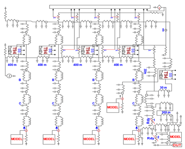
The calculation of atmospheric overvoltages is analyzed for the 400kV switchgear in the Kosovo Power System, which has a double busbar system and includes four transformer fields, two long-distance line fields with cable entry and a connecting field. Regarding the atmospheric overvoltages, the most critical situation is the situation during connection, when only one field of the transmission line and one transformer field is in operation. Fig.1. shows the equivalent scheme of the configuration, which is realized using the ATP/EMTP program. The insulation coordination process includes the selection of the insulation resistance of the equipment in accordance with the voltages that may appear in the network in which the equipment is installed, taking into consideration the working conditions and the characteristics of the equipment available for overvoltage protection.
In the assessment of isolation vulnerability, two contrasting approaches are most often applied: classical (deterministic) and statistical [7]. The deterministic approach means the calculation of atmospheric overvoltages under more unfavourable conditions, with large lightning current amplitudes which can be exceeded with a low probability. Such an approach is suitable for sensitivity analysis, which can easily and simply evaluate the impact of several parameters and assumptions for the risk.
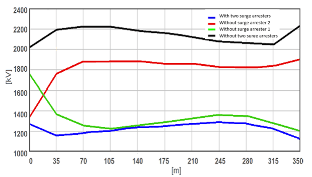
In Fig.2. are shown the maximum voltage values in the transformer that are reported when the lightning strikes the shielding wire on the upper part of the pole between the two first poles. The calculation is made for the atmospheric discharge whose current amplitude and slope are 121kA and 43kA/μs (According to the Berger distribution can be exceeded with a probability of less than 2%). Simulation is done for four cases, for combinations with and without surge arresters (in Fig.2. these surge arresters are marked with 1 and 2). As expected, from Fig.2. overvoltages are higher during atmospheric discharges at the top of the pole than along the conductor. The highest overvoltage values occur during the strike on first pole [8,9,10]. In Fig.3. are shown the waveforms of the voltage in the transformer for the four combinations for the placement of the surge arresters, during the lightning current strike of 121kA, 43kA/μs in the first pole, in the first half of the span and in the second pole.
From Fig.3.d) for efficient protection of the transformer, only surge arrester 2 (surge arrester before the transformer) is sufficient. On the other hand, surge arrester 1, which is significantly further from the transformer (300m), has a much smaller impact on limiting the surge in the transformer, and the protection of the transformer would not be sufficient [11, 12, 13].
In Fig. 4 is analysed the impact of the arrester on the overvoltage protection of the cable, the calculation of the maximum values of the voltage along the cable during the atmospheric discharge on the first pole. From the Fig.4. arrester 2 also has a dominant role in the protection of the cable, but the cable is fully protected only with the presence of both surge arresters.
In addition to discharges in the pole or shielding wire, atmospheric discharges are also possible despite the presence of the shielding wire. According to Fig.5, atmospheric discharges with an amplitude of 33 kA can strike the phase conductor with a probability of only 0.1%, and in this case a current slope of 43 kA/μs was assumed [14, 15]. In Fig. 5. are shown the maximum values of the voltage in the transformer in the case of a direct current strike with an amplitude of 33 kA and a slope of 43 kA/μs, in the phase conductor between the first two spans for the four combinations.
From Fig.5. it can be seen that lightning that strikes further away from the second pole, create very small overvoltages. Fig.6 show the voltage waveforms in transformers in case of atmospheric discharges of 33 kA, 43 kA/μs in the phase conductor: in the first pole, the first half space and the second pole [16].
In this case, the surge arrester 1 also does not have any significant effect on the protection of the transformer from overvoltage, but it does influence the protection of the cable. In Fig.7. are given the maximum values of the voltage along the cable during discharge directly to the phase conductor at the beginning of the first half span. From the figure, the cable is effectively protected if the two surge arresters are in place.

Simulation of switching overvoltages of a 400 kV line, ATP/EMTP
A. Uncontrolled switching of the 400 kV transmission line
In Fig.8. are presented the amplitudes of the overvoltages in phase A at the beginning and at the end of the transmission line for 500 statistical switching of the circuit breaker.Maximum overvoltage value of 2.2 p.u. appears in phase B at 191.2 km from SS1. The overvoltage waveforms at the beginning and at the end of the line in this case are shown in Fig.9. and Fig.10.

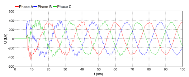

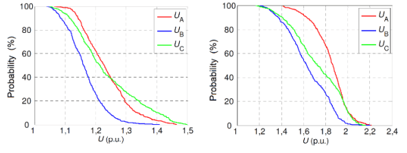
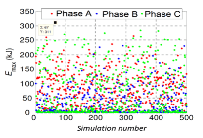
Fig.11. shows the cumulative values of the occurrence of phase overvoltages at the beginning and at the end of the transmission line [17]. The distributions U2% of the phase overlaps and between phases along the line are shown in Fig.12. The energy overload of the surge arrester in SS2 for 500 statistical switching of the circuit breaker is shown in Fig.13.


The amplitude of the switching currents depends on the switching moment of the circuit breaker poles and the length of the line. Fig.14. shows the voltages on the switch in SS1 during the uncontrolled switching of the line at the maximum network voltage. In this case, it leads to the appearance of switch closing currents, the amplitude of which reaches 5 times higher values in relation to the amplitude of the stationary capacitive current (Fig.15).
B. Controlled switching of the 400 kV transmission line.
Controlled switches have a very small pole distribution, so in simulations we predict it to be around ±0.5 ms. Distributions of U2% phase and line overvoltages per length of transmission line are presented in Fig. 16.
The energy load of the surge arrester in SS2 is shown in Fig.17


Fig.18. shows the voltages in the switch at SS1 during the controlled switching of the transmission line during the voltage crossing through zero. Controlled switching significantly reduces the amplitude of switching currents (Fig.18.).
C. Uncontrolled automatic repetitive switching on 400kV transmission line, SS1-SS2
Here are analysed switching overvoltages during repeated uncontrolled automatic switching on the line between SS1-SS2.
Since the capacitive measuring transformers are located at the ends of the line, after the disconnection of the circuit breaker, the momentary insulation breakdown cannot occur, so the breakdown fails on the line side. Fig.20. shows the voltages in SS2, while Fig.21. the energy load of the surge arrester in SS2 during automatic recloser from SS1.


The cumulative value of the energy load of the surge arrester in SS2 is shown in Fig.23.
D. Controlled automatic repetitive switching on 400kV transmission lines, SS1-SS2
The controlled switching of the transmission line is analyzed, and the polarity is the same as the polarity of the voltage remaining on the line.

Fig.24. shows the phase voltages in SS2 during repeated automatic single-pole switching from SS1 [18]. After the line outage now t=20ms, the voltage in phase A adjusts to the maximum value of positive polarity (t=360ms).
In Fig.25.is shown the energy load of the surge arrester in SS2 during controlled automatic repetitive switching from SS1.
Conclusion
Faults in transmission lines are mainly the result of atmospheric discharges, and the cause can be a lightning strike on the pole, on the shielding wire or a direct strike on the phase conductor. During the design of the atmospheric discharge protection system, attention should be paid to parameters such as the density of lightning strikes on the transmission line, the specific resistance of the earth and the characteristics of the poles. Such parameters are the basis for the selection of insulation levels and the type of grounding that will directly affect the occurrence of overvoltage in the transmission lines. Most often, the stroke occurs at the top of the pole of the transmission lines or at the shielding wire where the overvoltage between the pole and the phase conductor is reached. The breakdown of the insulator will depend on the amplitude and slope of the lightning current, the earthing resistance, the insulator distance, the atmospheric conditions, the value of the phase voltage and the place of impact. The impact of the breakdown can be reduced by surge arresters which, in addition to this role, serve to prevent failure of transmission lines and to improve the protection of transformer substations. The results show how the Kosovo’s Power System is affected when the lightning strikes at different points of the transmission lines, such as transmission line poles, shielding wires, or even directly on the phase conductors.
REFERENCES
[1] T.Horvath, Understanding lightning and lightning protection, A multimedia teaching guide, Budapest University of Technology and Economics, Hungary, 2006
[2] E.M. Bazelyan, Y.P. Raizer, Lightning Physics and Lightning Protection, Bristol and Philadelphia, 2000
[3] P.E.Munhoz Rojas, C.L.da Silva Pinto, Calculations of lightning-induced voltages in medium voltage distribution lines, IX International Symposium on Lightning Protection, November 2007, Foz do Iguaqu, Brazil
[4] A. Morkvenas, S. Gudzius, D. Sakauskaite, The Analysis of the Overvoltages Protection Development and their Characteristics Influence on the Overvoltages Level, Przeglad Elektrotechniczny, Vol 2012, 7b, pg. 186
[5] L.L.Grigsby, Power systems’, CRC Press, New York, Chapter 6, 2006
[6] L. Van der Sluis, Transients in Power Systems, Delft University of Technology, The Netherlands, 2001
[7] L. Prikler, H.K. Hoidalen, ATPDraw,version 5.6,Users’ Manual, November, 2009, Norway
[8] Y.C.J.Liu, H.G.P.Hunt, M.D.Grant, K.J.Nixon, Observations of lightning discharges on Brixton tower, paper presented at 30th International Conference on Lightning Protection, University of Bologna, Cagliari, Italy, 2010
[9] Huang Hua, Jin Heng, Fu Chenzhao, Si Wenrong: Study on a new method for overvoltage measurement using CVT, Przeglad Elektrotechniczny, Vol 2011, 9a, pg.321
[10] Y. Hase, Handbook of Power System Engineering, 2007
[11] A.Nag, V.A.Rakov, Positive lightning: An overview, new observations, and inferences, J. Geophys. Res.,117, D08109, 2012
[12] R.H.T.Chamie Filho, R.M.S.de Oliveira, C.L.da S.S.Sobrinho, Simulations of Lightning Strokes near Transmission Lines in Urban Environments by Using the Finite-Difference TimeDomain Method, Journal of Microwaves, Optoelectronics and Electromagnetic Appliances, Vol.8,No.1,June 2009
[13] M. Jaroszewski, J. Pospieszna, P. Ranachowski, F. Rejmund, Modeling of overhead transmission lines with line surge arresters for lightning overvoltages, Application of Line Surge Arresters in Power Distribution and Transmission Systems, Cigre, Cavtat, 2008
[14] S.K. Omar Dau, Modelling of lightning overvoltages for the protection of transmission lines by means of shielding wires and surge arresters, Poland, 2008
[15] B. Franc, M.Šturlan, I. Uglešić, Z. Hebel: “Primjena sustava za lociranje munja u vođenju elektroenergetskog sustava“, studenoga 2011
[16] F. Fiamingo, B. Kuca, C. Mazzetti, T. Kisielewicz, D. Krasowski: Impact of Overvoltage Shape Caused by Lightning Stroke on Sensitive Apparatus Protection by Means of SPD,
Przeglad Elektrotechniczny, Vol 2012,9b, pg.282
[17] N. Kosoc, Sustav za zastitu nadzemnih vodova od atmosferskog praznjenja, Rjeka, Rujan, 2015
[18] V. Hinrichsen, Metal-Oxide Surge Arrester, Fundamentals, 1st ed. Siemens AG, Berlin, Germany, 2001.
Authors: First author is Prof. Ass. Dr. Bahri Prebreza, E-mail: bahri.prebreza@uni-pr.edu; Second author is Msc. Ass. Nuri Berisha* corresponding author, E-mail: nuri.berisha@uni-pr.edu.Third author is Msc. Bashkim Statovci, E-mail: bashkim.statovci@rks-gov.net; University of Prishtina, Faculty of Electrical and Computer Engineering, Street ”Sunny Hill”, nn, 10000, Prishtina.
Source & Publisher Item Identifier: PRZEGLĄD ELEKTROTECHNICZNY, ISSN 0033-2097, R. 99 NR 7/2023. doi:10.15199/48.2023.07.03
