Published by 1. Mohd Sanusi Bin Mohd Mokhtar1, 2. Mohd Shafie Bin Bakar2, 3. Mohd Shawal Bin Jadin2, Paya Besar Community College (1), Faculty of Electrical and Electronics Engineering Technology, Universiti Malaysia Pahang (UMP) (2) ORCID: 2. 0000-0003-2905-6449; 3.0000-0001-6253-7821
Abstract. In this paper, a simulation study on H5 topology is presented. H5 topology is a commonly used inverter in photovoltaic (PV) systems because it is cost-effective, simple, and highly efficient. The study compares the performance of H4 topology, H5 topology, and an improved version of H5 topology in terms of leakage current. The power device was subjected to Unipolar Sinusoidal Pulse Width Modulation (SPWM) technique to determine the overall operation within a switching frequency range of 2 kHz to 20 kHz. The input system utilized a PV Matlab/Simulink model that specified a maximum power of 213.15 Watt and Open Circuit Voltage (Voc) of 36.3 V. The improved H5 topology demonstrated a significant reduction in leakage current, measuring 0.015 A compared to the conventional H5 topology’s 0.02 A.
Streszczenie. W artykule przedstawiono badanie symulacyjne topologii H5. Topologia H5 jest powszechnie stosowanym falownikiem w systemach fotowoltaicznych (PV), ponieważ jest opłacalna, prosta i wysoce wydajna. Badanie porównuje wydajność topologii H4, topologii H5 i ulepszonej wersji topologii H5 pod względem prądu upływu. Urządzenie zasilające zostało poddane technice jednobiegunowej sinusoidalnej modulacji szerokości impulsu (SPWM) w celu określenia ogólnej pracy w zakresie częstotliwości przełączania od 2 kHz do 20 kHz. System wejściowy wykorzystywał model PV Matlab/Simulink, który określał maksymalną moc 213,15 W i napięcie obwodu otwartego (Voc) 36,3 V. Ulepszona topologia H5 wykazała znaczne zmniejszenie prądu upływu, mierząc 0,015 A w porównaniu z konwencjonalną topologią H5 0,02A. (Analiza pracy falowników H5 w instalacji fotowoltaicznej)
Keywords: photovoltaic system (PV), efficiency, inverter, leakage current
Słowa kluczow: instalacja fotowoltaiczna, sprawność, falownik, prąd upływu
Introduction
Generation of energy from renewable resources, specifically photovoltaic (PV) is becoming popular due to pollution free nature. As PV generation produces direct current and utility grids operate on alternating current, an inverter is needed between PV and the grid for a system integration [1]. For grid-connected PV systems, inverters are crucial parts that serve as links between the grid panel and the PV panel [2][3]. There are two types of inverters available which are galvanic isolated and non-isolated. Transformer less inverters are gaining popularity in the low to medium power capacity domestic market because of their reduced size, weight and cost, and improved efficiency [4]. A direct ground current path between the PV panel and the grid is possible in the absence of galvanic isolation. Because of the significant stray capacitance (CPV) between the PV and grid grounds, this current can emerge as shown in Fig. 1. As a result, a fluctuating voltage, or common mode voltage (CMV), can excite the parasitic capacitor’s resonant circuit. This can produce electrical interference, which can lead to concerns including power quality issues and device malfunction. In transformer less PV systems, high leakage current is a significant concern as it can cause increased grid current ripples, system losses, potential induced degradation to solar panels, and electromagnetic interference [5]–[7].
The combination of galvanic isolation and the common-mode voltage (CMV) clamping approach has led to the development of numerous research ideas that aim to reduce leakage current. These methods aim to prevent leakage current from flowing through the grounding system by providing an alternative path, thus increasing system safety and improving performance [8]. By minimizing leakage current, transformer less PV systems can become a more viable alternative to traditional isolated systems [9].
Improved Transformer less Inverter
A. A structure of the improved H5 Inverter
This paper describes an improved H5 [10] inverter that offers lower leakage current and higher efficiency than conventional H5 inverters [16]. The improved topology achieves this by connecting two freewheeling diodes to the two phase legs of the conventional H5 inverter. The switches S1 to S5 are used in the proposed improved H5 inverter. The S1, and S3 switches create a freewheeling path for the circulating current through the filter inductors and the grid. The diodes, D1 and D2, help to achieve a constant common-mode voltage (CMV), which is clamped to half of the input voltage. This results in the elimination of CM leakage current, which is a significant problem in conventional H5 inverters [10] [11][13]–[17].

B. Operating Principle and Switching Techniques
The switching scheme of the inverter is a unipolar SPWM modulation scheme, which helps prevent the injection of harmonics into grid current and reduces power losses. Fig.3. shows the individual pulses needed for the switches of the proposed inverter [18] [19].

C. Analysis of the results and performance comparison
The designed transformer less inverter’s performance is evaluated through MATLAB/Simulink simulation results, with all three topologies simulated using the settings specified in Table 1 and Table 2. To create parasitic capacitance (Cpv), two capacitors are connected to the source and ground terminals, and two sets of inductors are attached to the H-bridge arms. Additionally, a capacitor is connected in parallel with the load to establish the LCL filter. The simulation employs an RMS grid voltage of 230 V and a frequency of 50 Hz, with a switching frequency (fs) range of 2 kHz to 20 kHz. These parameters enable the researchers to conduct a thorough assessment of the transformer less inverter’s performance and compare the results to determine the optimal topology.
Table 1. Inverter Specification

Fig. 4 shows that during the freewheeling period, a large fluctuation in the VAN and VBN of the standard H4 topology, with magnitudes up to 100 V, can be observed. These oscillations then lead to common-mode voltage (CMV) oscillations, with magnitudes up to 100 V, which result in a significant amount of leakage current being produced. This demonstrates that more than simply galvanic isolation procedures and modulation techniques are needed to establish a constant CMV.
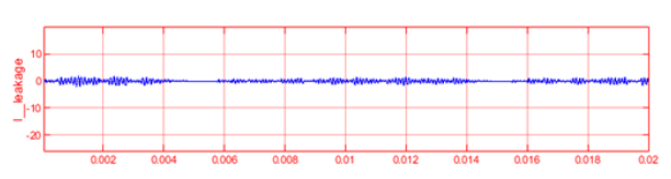
Fig. 5 indicates that there are considerable oscillations in both VAN and VBN with amplitudes of up to 100 V in the H5 architecture. Furthermore, the common-mode voltage (CMV) oscillates with magnitudes of up to 200 V. These findings imply that the leakage current is not eliminated in this configuration.
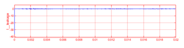
Fig. 6. presents the precisely opposite voltages, VAN and VBN, of the enhanced inverter, which demonstrate a consistent common-mode voltage (VCM) of 200 V during both the conduction and freewheeling periods. The figure also depicts the VAB of the improved inverter, as well as the grid voltage and grid current. As a result of the stable VCM, a significantly reduced amount of leakage current, approximately 15 mA, is detected in the improved inverter compared to the conventional H4 and H5 configurations.

The relationship between leakage current and switching frequency of inverter topologies are presented in Fig. 7. and Fig. 8. The conventional H4 topology exhibits low current leakage at the beginning, with 59 mA at a 2 kHz switching frequency before increasing to 500 mA at 4 kHz. The current leakage of the conventional H4 topology then decreases at 4 kHz and 6 kHz before experiencing a sudden increase at 10 kHz, 12 kHz and 14 kHz, with a highest recorded value of 1097 mA. The current leakage then decreases again to 226 mA at 16 kHz before reaching its lowest recorded value of 43 mA at 18 kHz.

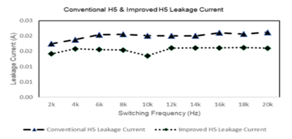
Both the conventional H5 and improved H5 topologies recorded lower current leakage values, with a range between 14 mA and 21 mA as shown in Fig. 9. The improved H5 topology recorded lower current leakage compared to the conventional H5, with the lowest recorded value being 14 mA for the improved H5 and 21 mA for the conventional H5.
Conclusion
The improved H5 topology is of particular interest, as simulation results are presented to provide new insights into the effects of duty ratio and switching frequency on the safe operation of a grid-connected PV system.
The study evaluates the transformer less inverter topologies by analyzing leakage current performance which can affect the reliability and overall performance of a PV system. The findings highlight the importance of carefully selecting the duty ratio and switching frequency to achieve optimal performance and avoid potential safety hazards. The improved H5 topology exhibits superior performance compared to the conventional H4 [20] and H5 topologies. The leakage current in the improved H5 topology was only 15 mA, which is much lower than the 360 mA recorded for the H4 topology in the simulation. In summary, the improved H5 topology transformer less inverters exhibit numerous advantages over conventional transformer less inverters. This makes them highly suitable for use in gridconnected solar PV systems and other renewable energy applications. Based on the simulation results, it can be concluded that the proposed design is effective in improving the overall performance of the system and overcoming the limitations associated with conventional methods.
Acknowledgments – This work was financed by Universiti Malaysia Pahang under research grant RDU200330. The authors would like to acknowledge the support of this work by Universiti Malaysia Pahang and the facility support provided by the Sustainable Energy & Power Electronics Research GroupResearch Group, Faculty of Electrical and Electronics Engineering Technology, University Malaysia Pahang.
REFERENCES
1 J. Jiang, S. Pan, J. Gong, F. Liu, X. Zha, and Y. Zhuang, “A Leakage Current Eliminated and Power Oscillation Suppressed Single-Phase Single-Stage Nonisolated Photovoltaic Grid-Tied Inverter and Its Improved Control Strategy,” IEEE Trans Power Electron, vol. 36, no. 6, pp. 6738–6749, Jun. 2021, doi: 10.1109/TPEL.2020.3035033.
2 N. Attou, S.-A. Zidi, M. Khatir, and S. Hadjeri, “Grid-Connected Photovoltaic System,” 2020, pp. 101–107. doi: 10.1007/978-981-15-5444-5_13.
3 M. Venkatesan, R. Rajeswari, and K. Keerthivasan, “A survey of single phase grid connected photovoltaic system,” in IEEE Proceedings of the INternational Conference On Emerging Trends in Science Engineering and Technology: Recent Advancements on Science and Engineering Innovation, INCOSET 2012, Jul. 2014, pp. 404–408. doi: 10.1109/incoset.2012.6513941.
4 T. K. S. Freddy, N. A. Rahim, W. P. Hew, and H. S. Che, “Comparison and analysis of single-phase transformerless gridconnected PV inverters,” IEEE Trans Power Electron, vol. 29, no. 10, pp. 5358–5369, 2014, doi: 10.1109/TPEL.2013.2294953.
5 Soham Deshpande; N. R. Bhasme, “A review of topologies of inverter for grid connected PV systems,” IEEE, 2018.
6 Ó. López, R. Teodorescu, F. Freijedo, and J. Dovalgandoy, “Leakage current evaluation of a singlephase transformerless PV inverter connected to the grid,” in Conference Proceedings – IEEE Applied Power Electronics Conference and Exposition – APEC, 2007, pp. 907–912. doi: 10.1109/APEX.2007.357623.
7 A. Adhikary and M. Shamim Anower, “Reduction of leakage current in a single phase transformerless grid connected PV system,” in 2021 International Conference on Automation, Control and Mechatronics for Industry 4.0, ACMI 2021, Jul. 2021. doi: 10.1109/ACMI53878.2021.9528294.
8 L. Wang, Y. Shi, Y. Shi, R. Xie, and H. Li, “Ground Leakage Current Analysis a Suppression in a 60-kW 5-Level T-Type Transformerless SiC PV Inverter,” IEEE Trans Power Electron, vol. 33, no. 2, pp. 1271–1283, Feb. 2018, doi: 10.1109/TPEL.2017.2679488.
9 T. Kerekes, D. Sera, and L. Mathe, “Leakage current measurement in transformerless PV inverters,” in Proceedings of the International Conference on Optimisation of Electrical and Electronic Equipment, OPTIM, 2012, pp. 887–892. doi: 10.1109/OPTIM.2012.6231835.
10 M. H. Mondol, S. Prokash Biswas, M. K. Hosain, and M. Rafiqul Islam Sheikh, “An Improved Single Phase Transformerless H5 Inverter with Minimized Leakage Current,” in 3rd International Conference on Electrical, Computer and Telecommunication Engineering, ICECTE 2019, Dec. 2019, pp. 73–76. doi: 10.1109/ICECTE48615.2019.9303539
11 M. N. H. Khan, M. Forouzesh, Y. P. Siwakoti, L. Li, T. Kerekes, and F. Blaabjerg, “Transformerless Inverter Topologies for Single-Phase Photovoltaic Systems: A Comparative Review,” IEEE J Emerg Sel Top Power Electron, vol. 8, no. 1, pp. 805–835, Mar. 2020, doi: 10.1109/JESTPE.2019.2908672
12 T. Kerekes, R. Teodorescu, P. Rodríguez, G. Vázquez, and E. Aldabas, “A New high-efficiency single-phase transformerless PV inverter topology,” IEEE Transactions on Industrial Electronics, vol. 58, no. 1, pp. 184–191, Jan. 2011, doi: 10.1109/TIE.2009.2024092
13 L. Zhou and F. Gao, “Low leakage current single-phase PV inverters with universal neutral-point-clamping method,” in Conference Proceedings – IEEE Applied Power Electronics Conference and Exposition – APEC, May 2016, vol. 2016-May, pp. 410–416. doi: 10.1109/APEC.2016.7467905
14 E. E. Ahsan, M. A. Shobug, M. M. H. Tanim, and M. H. Reza, “Harmonic distortion reduction of transformerless inverter’s output voltage using 5-Level Single-phase inverter and LCL filter,” in 2020 2nd International Conference on Advanced Information and Communication Technology, ICAICT 2020, Nov. 2020, pp. 251-256 doi: 10.1109/ICAICT51780.2020.9333510.
15 X. Guo, “A Novel CH5 Inverter for Single-Phase Transformerless Photovoltaic System Applications,” IEEE Transactions on Circuits and Systems II: Express Briefs, vol. 64, no. 10, pp. 1197–1201, Oct. 2017, doi: 10.1109/TCSII.2017.2672779
16 H. Albalawi and S. A. Zaid, “An H5 transformerless inverter for grid connected PV systems with improved utilization factor and a simple maximum power point algorithm,” Energies (Basel), vol. 11, no. 11, Nov. 2018, doi: 10.3390/en11112912
17 H. Albalawi and S. A. Zaid, “An H5 transformerless inverter for grid connected PV systems with improved utilization factor and a simple maximum power point algorithm,” Energies (Basel), vol. 11, no. 11, Nov. 2018, doi: 10.3390/en11112912.
18 B. Yang, W. Li, Y. Gu, W. Cui, and X. He, “Improved transformerless inverter with common-mode leakage current elimination for a photovoltaic grid-connected power system,” IEEE Trans Power Electron, vol. 27, no. 2, pp. 752–762, 2012, doi: 10.1109/TPEL.2011.2160359.
19 M. K. Islam, M. M. Rahman, and M. F. Rabbi, “Transformer less, lower THD and highly efficient inverter system,” in Proceedings of 2015 3rd International Conference on Advances in Electrical Engineering, ICAEE 2015, Jul. 2016, pp. 293–296. doi: 10.1109/ICAEE.2015.7506853
20 T. Annamalai and K. Udhayakumar, “Simulation and analysis of various H-bridge inverter topologies employed in cascaded multilevel inverter,” in 2018 International Conference on Emerging Trends and Innovations In Engineering And Technological Research, ICETIETR 2018, Nov. 2018. doi: 10.1109/ICETIETR.2018.8529034
Authors: Mohd Sanusi Bin Mohd Mokhtar. Email: m.sanusi05@gmail.com, Dr Mohd Shafie Bakar, Faculty of Electrical and Electronics Engineering Technology, University Malaysia Pahang. Email: shafie@ump.edu.my, Dr. Mohd. Shawal Jadin. Email: mohdshawal@ump.edu.my
Source & Publisher Item Identifier: PRZEGLĄD ELEKTROTECHNICZNY, ISSN 0033-2097, R. 99 NR 10/2023. doi:10.15199/48.2023.10.09
