Published by Nahid MUFIDZADA1, Gulgaz İSMAYILOVA2, Azerbaijan State Oil and Industry University, Power Faculty, “Electroenergetics” department, Baku, Azerbaijan
ORCID: 0000-0003-4063-2128, 0000-0003-0063-2020
Abstract. A new method has been developed to determine the location and degree of insulation damage in cables. An electrical circuit is defined, using which this task is performed. According to this scheme, one end of the cable is connected to a pulsed voltage source through a small resistance, and the other end is grounded through a resistance equal to its wave impedance. By measuring the voltages at the beginning and at the end of the cable, curves are drawn depending on the ratio of voltages at the end and at the beginning of the cable from the distance between the point of damage and the beginning of the cable, with various degrees of damage to the insulation in it. Using the curves of this dependence α=f(x/l), the location and degree of insulation damage in cables is determined.
Streszczenie. Opracowano nową metodę określania miejsca i stopnia uszkodzenia izolacji w kablach. Definiowany jest obwód elektryczny, za pomocą którego wykonywane jest to zadanie. Zgodnie z tym schematem jeden koniec kabla jest podłączony do pulsującego źródła napięcia przez mały opór, a drugi koniec jest uziemiony przez opór równy jego impedancji falowej. Mierząc napięcia na początku i na końcu kabla, rysuje się krzywe w zależności od stosunku napięć na końcu i na początku kabla z odległości pomiędzy miejscem uszkodzenia a początkiem kabla, przy różne stopnie uszkodzenia izolacji w nim. Korzystając z krzywych tej zależności α=f(x/l) określa się miejsce i stopień uszkodzenia izolacji w kablach. (Określenie miejsca i stopnia uszkodzenia izolacji w kablach)
Keywords: Cable, insulation, degree of insulation damage, impulse voltage.
Słowa kluczowe: Kabel, izolacja, stopień uszkodzenia izolacji, napięcie udarowe
Introduction
Increased requirements are imposed on the reliability of cable lines and, consequently, on their insulation, since a lot of time and money are spent on finding the place of damage and, especially, on eliminating it in underground lines.
Causes of defects in cables are very diverse. Defects appear mainly in the weakest elements of cable insulation in the form of air inclusions, in which such dangerous processes as ionization and partial discharges develop. Determining the location and degree of damage in a cable line is a very important task, the relevance of which is currently confirmed by numerous studies by scientists from different countries [1,2,3,4].
Carrying out preventive tests can not always accurately determine the nature of the malfunction, and in some cases may not determine the presence of damage at all. Tests can only determine the presence of a fault in cables if its insulation level is reduced by at least 80 – 90% [5]. At the moments of an accident, cables often receive secondary damage. By type, such damage is divided into short circuits (in networks with isolated neutral) and breaks [6].
To determine the distance from the end of the cable to the point of damage in case of wire breaks and interphase and single-phase short circuits, the impulse research method is widely used [2,4].
The inevitable material and financial losses caused by the failure of the cable line (CL) force us to look for the most effective and minimizing these losses ways to eliminate damage. The correct choice of the method and equipment for searching for damage sites determines the quality of the solution to the problem, i.e. the maximum probability of correctly determining the location of the damage and the minimum time spent on this [8].
Analysis and purpose of the work
The presented article provides a method that can also be called a pulse method for determining the location and degree of cable damage. The determination of the location and the degree of damage to the insulation, as well as the location of the phase wire break during impulse effects on the cable, are considered. To do this, a pulsed voltage is applied to the cable input, which can be used as a pulsed standard wave of 1.2/50 μs of small amplitude through a sufficiently small resistance so that the cable input does not have a constant voltage equal to the applied voltage, and also be able to measure the current in that part. The end of the cable should also be grounded through a resistance to measure current and voltage in this part of the cable. In order to avoid the influence of the reflected wave at the end of the cable, the values of this resistance should be taken equal to the characteristic impedance of the cable. Otherwise, there will be two points in the cable (the point of insulation damage and the end of the cable), at which reflection and refraction of the wave will occur, leading to the complication of the wave process in the damaged cable. The design scheme is shown in Figure 1.

In the study, a cable with paper insulation and viscous impregnation was used, with a cross section of 120 mm2 with a rated voltage of 35 kV [8]. The length of the cable was assumed to be 1000 m. The study can be applied to metal cables of all types.
In calculations, the cable is represented by a traditional equivalent circuit in the form of a chain consisting of 30 elements.
Insulation damage and phase wire breaks were considered separately at 15 points located at distances of 0.067∙n from the beginning of the cable, where n are the numbers of these 15 points, 0.067 is the relative length between two adjacent sections. Determinations of the degree of insulation damage were carried out for cases of insulation damage of 30, 50, 60, 70, 80, 90, 95 and 100 percent.
Results and Discussion
The calculations were carried out using the algorithmic language OrCAD-17.
The results of calculations for determining the location and degree of insulation damage are shown in Table 1 and in Figure 2 – 5.
As can be seen from Table 1, regardless of the degree of damage to the insulation and its location in the cable, there is a slight change in the voltage values in the section (0 – 0.4) l of the cable, and in the section (0.4 – 1.0) l the voltage does not change. The deterioration of the insulation affects the voltage at the beginning of the cable, only for faults very close to the beginning of the cable.
As for the voltage at the end of the cable, this voltage along the cable varies in a very narrow limit for each value of the degree of damage, but with an increase in the degree of damage, starting from a value of 80%, this voltage decreases ( Table 1).
To generalize the obtained results, the dependence of the voltage ratio at the end and at the beginning of the cable (𝛼 = 𝑈к / 𝑈nom) on the distance of the damage point from the beginning of the cable, i.e. dependence α = f(𝑥/l). This dependence for all considered degrees of insulation damage, except for 100% damage, is shown in Figure 2.

At 100% insulation failure, the remaining part of the cable between its end and the damaged point is short-circuited at the fault, and therefore the current and voltage in the shorted part of the cable become zero.
In Figure 2, curves – 1, 2, 3, 4, 5, 6 and 7 refer to the degrees of damage respectively 30, 50, 60, 70, 80, 90 and 95 percent.
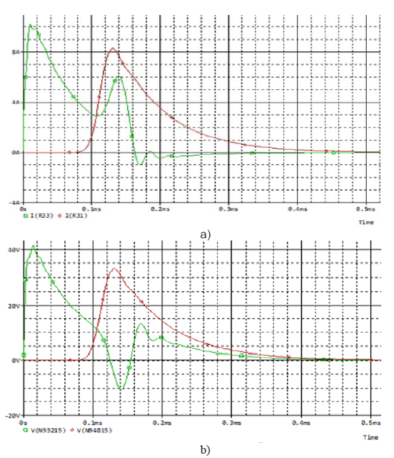
As an example, Figure 3 shows the voltage curve at the beginning and at the end of the cable with a degree of damage to its insulation of 90% in the middle of the cable.
According to Figure 2, determination of the degree of insulation damage and its place in the cable is possible if the insulating properties of the cable are reduced by at least 80% (curves – 1, 4 and 7). At lower degrees of insulation damage, the corresponding curves are located very close to each other, which makes it impossible to determine either the degree of insulation damage or its place in the cable.
According to Figure 2, determination of the degree of insulation damage and its place in the cable is possible if the insulating properties of the cable are reduced by at least 80% (curves – 1, 4 and 7). At lower degrees of insulation damage, the corresponding curves are located very close to each other, which makes it impossible to determine either the degree of insulation damage or its place in the cable.
The degree of insulation damage and its location in the cable are determined according to the value of α. The values of currents in the cable are similar to the values of voltages in it. According to these values, the ratio of currents at the beginning and at the end of the cable is also determined, and the dependence of this ratio on the distance of the fault point from the beginning of the cable is plotted for various degrees of damage in it, i.e. the dependence 𝛽 = İnom/İк is similar to the dependence 𝛼 = 𝑈к / 𝑈nom. Dependence 𝛽 = İnom/İк is shown in Fig.4.
Like the dependence 𝛼 = 𝑓1 (𝑥/l), the dependence 𝛽 =𝑓2 (𝑥/l) also shows that the excessive proximity of the curves related to lower degrees of damage (up to 80%) does not allow determining the degree of insulation damage and the location of the damage in the cable . A slight discrepancy between these curves exists only in the initial part of the cable in the section (0 – 0.15) l, and in the rest of it they practically merge.
Such a merging of the curves shown in Figs. 2 and 4, corresponding to the degree of insulation damage by less than 80%, makes it possible to replace them with one curve. This allows all faults below 80% to be considered as 80% fault and to locate them in the cable using the 80% insulation fault curve.
The shape of the dependency curves 𝛼 = 𝑓1 (𝑥/l), 𝛽 =𝑓2 (𝑥/l), shown in Figures 2 and 4 show that to determine the degree of insulation damage and its location in the cable, the use of curves in Figure 2 (curves related to voltages) is more convenient.
As you can see, in Figure 4 there is no curve related to 100 percent damage to the cable insulation. As noted above, with 100% insulation damage, the current and voltage at the end of the cable are zero. Therefore, for this case, the dependence of the ratio of the current at the beginning of the cable, corresponding to shorts at its various intermediate points, and the current at the end of the cable, in the absence of shorts, on the distance of the fault point from the beginning of the cable is considered. Such dependence is shown in Figure 5.
Table 1. Voltage values at the beginning and at the end of the cable at various degrees damage to its insulation at various points


In this case, as the insulation damage point moves away from the beginning of the cable, the current at the beginning of the cable decreases monotonically due to an increase in distance and, accordingly, resistance.
According to Figure 5, the location of 100 percent insulation failure in the cable is easily located.
To determine the location of the wire break of the phases in the cable, a corresponding calculation was made, in which the wire break was considered at the above 15 points of the cable during the impulse action on the cable, and the voltage at the beginning of the cable was measured.

According to the results of the calculations, the dependence of the voltage ratios at the beginning of the cable with breaks and in the absence of a break in the phase wire in it was plotted on the remoteness of the wire break in the cable. This dependence is shown in Figure 6.
As can be seen from Figure 6, as the distance of the phase wire break point from the beginning of the cable increases, the voltage at the beginning of the cable decreases monotonically. This shape of the curve also makes it easy to determine the location of the phase wire break.

Conclusions
1. A new method has been developed to determine the location and degree of insulation damage, as well as the location of the phase wire break in cables.
2. An electrical circuit has been selected, according to which the location and degree of insulation damage are determined, as well as the location of the phase wire break in the cables.
3. Considering insulation damage of varying degrees at different points of the cable, curves were drawn depending on the ratio of voltages at the end and at the beginning of the cable on the distance between the point of damage and the beginning of the cable, with various degrees of insulation damage – α = f(x/l), which allow you to determine the location and the degree of damage to the cable insulation.
The possibility of determining the location of the wire break of the cable phases is considered using the dependence of the voltage ratio at the beginning of the cable when the wire is broken at its various points and in the absence of a break on the distance of the wire break from the beginning of the cable.
REFERENCES
1. Florkowska B., Florkowski M., Zydroń P., Pomiary i analiza wyładowań niezupełnych w układach izolacyjnych wysokiego napięcia przy narażeniach eksploatacyjnych, Przegląd Elektrotechniczny, 2010, 4, 241-244.
2. Florkowski M., Forkowska B., Rybak A., Zydron P., Migration effects at conductor / XLPE interface subjected to partial discharges at different electrical stresses, IEEE Trans. on Diel. and Electr. Insul., 2015, 22, 456 – 462
3. A. Shimada, M. Sugimoto, H. Kudoh, K. Tamura, and T. Seguchi, “Degradation distribution in insulation materials of cables by accelerated thermal and radiation ageing,” IEEE Transactions on Dielectrics and Electrical Insulation 20, pp. 2107, 2013.
4. A. Shimada, M. Sugimoto, H. Kudoh, K. Tamura, and T. Seguchi, “Degradation mechanisms of silicone rubber (SiR) by accelerated ageing for cables of nuclear power plant,” IEEE Transactions on Dielectrics and Electrical Insulation 21, pp.16, 2014..
5. T. Seguchi, K. Tamura, H. Kudoh, A. Shimada, and M. Sugimoto, “Degradation of cable insulation material by accelerated thermal radiation combined ageing,” IEEE Transactions on Dielectrics and Electrical Insulation 22, pp. 3197, 2015.
6. Stepanov, V.M. Diagnostics of the technical condition of power cable lines with a voltage of 35-500 kV / V.M. Stepanov, P.A. Borisov // News of TulGU. Technical science. Issue 6. – Part 1. -pp.66-71, 2011.
7. Gotman V.I. Short circuits and unbalanced modes. Study, for universities. M: Publishing House of Tomsk Polytechnic University, 2013. – 240 p.
8. Lebedev, G.M. Improving the efficiency of operation of 6-10 kV cable lines in power supply systems based on non-destructive diagnostics. / G.M. Lebedev // Moscow Energy Institute. – M., p. 408, 2007.
Authors: Mufidzada Nahid1, İsmayilova Gulgaz2,,2Azerbaijan State Oil and Industry University, Power Faculty, “Electroenergetics” department, Baku, Azerbaijan,1 Associate professor, (gulgaz77@mail.ru)
Source & Publisher Item Identifier: PRZEGLĄD ELEKTROTECHNICZNY, ISSN 0033-2097, R. 99 NR 10/2023. doi:10.15199/48.2023.10.18
