Published by Łukasz KNYPIŃSKI1,2, Jacek KRUPIŃSKI2, Poznan University of Technology(1), Krupinski Cranes Sp. z o.o.(2)
Abstract. The paper presents the results of experimental research concerning the application of the permanent magnet synchronous motors for tower cranes. The modern permanent magnet synchronous motors (PMSM) are characterized by better operating parameters in relation to squirrel cage induction machines. In the first stage of our research, the designed crane has been equipped with commercially produced permanent magnet synchronous motors. The test bench for examination of PMSM properties was built. The preliminary selected permanent magnet (PM) motors were experimentally tested to verify its performances in crane applications. Selected results of experimental research for hoist winch drive are presented and discussed.
Streszczenie. W pracy przedstawiono wyniki badań eksperymentalnych dotyczące zastosowania silników synchronicznych z magnesami trwałymi do napędu żurawi wieżowych. Współcześnie produkowane silniki synchroniczne z magnesami trwałymi charakteryzują się lepszymi parametrami eksploatacyjnymi w stosunku do silników indukcyjnych. W pierwszym etapie badań projektowany żuraw dźwigowy został wyposażony w produkowane seryjnie silniki. W celu oceny przydatności zaproponowanych silników zbudowano stanowisko pomiarowe do badania właściwości i charakterystyk. Przedstawiono i omówiono wybrane wyniki badań eksperymentalnych. Zastosowanie magnetoelektrycznych silników synchronicznych do napędu żurawi dźwigowych.
Keywords: tower cranes, permanent magnet synchronous motors, hoist winch drive, efficiency.
Słowa kluczowe: żurawie dźwigowe, magnetoelektryczne silniki synchroniczne, układ napędowy wciągarki, sprawność.
Introduction
The tower cranes are the biggest constructed cranes machines. The crane is equipped with several different motor-drives, each of with is responsible for movement in a different plane. In addition, each tower crane has other electrical motors like fans. In construction of the tower crane, the following motor-drives are used: (a) the slewing drive, (c) the trolley travelling drive and (c) the hoist winch drive. At present the three-phase squirrel cage induction motors are commonly used in construction of the tower cranes [1, 2]. In European Union the new efficiency standard (IE3) – premium efficiency standard has been introduced. Since 1 January 2017, the minimum efficiency IE3 must be maintained for induction motors with rated power 7.5 to 375 kW. Such type of motors with improved efficiency will replace the classical induction motors in modern designs of cranes.
The KR-90-5 type tower crane available in Krupinski commercial offer has an installed mechanical power of motordrives equal 25 kW [18]. The reduction of the energy consumption in the motor-drives in one crane about 5% may lead to significant energy savings. On the whole our country the electric power consumption by all tower cranes leads to a reduction of the energy resources, which also contributes to an increase on electric energy demand. Increasing the demand for electricity leads to an increase on pollution of the natural environment in Poland. This is because the major part of electric energy is produced using fossil fuels. With a slight improvement in the efficiency of a single machine, we can achieve large energy savings.
The main purpose of our research is the construction of a tower crane, which will be equipped with permanent magnet synchronous motors. The application of such type of motors is to ensure reduction of the consumption of the electric energy in designed device. The PMSM are characterized by better operating parameters in comparison to modern high-efficiency induction motors [3, 4, 5, 6, 7, 8]. The permanent magnet (PM) motors have many advantages, such as: high efficiency, high torque to mass ratio, a high power factor and wide operation range [9, 10, 11, 12, 13, 15]. In addition, the application of the permanent magnet synchronous motors will reduce the noise produced by operating tower crane. This is because such type of motor does not need a fans. In this article the application of the PM synchronous motor for hoist winch drive is presented. The presented experimental tests allow determining the efficiency for the drive system.
Requirements for crane drives
In principle, tower cranes, depending on their type, are equipped with 3 to 4 different drives. The two main drives are the hoist winch drive and slewing drive [14]. The third one is the drive for boom inclination. In cranes with the trolley jib this is the trolley travelling drive and in cranes with the luffing jib, this is the drive which changes the jib positioning angle. The fourth drive, which is presently, used more and more seldom is the crane travel drive allowing for the movement along the rail track. There is also the fifth drive in the bottom-slewing, self-erecting crane class – it is the drive of the crane setup arrangement system. In practice, this is the fourth drive as the application of the travel mechanism in the case of these cranes is marginal. The hoist drive is the drive adapted to the crane class.
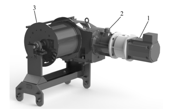
The task of the hoist drive is to carry out the most optimal weight lifting and lowering operation possible within the range assumed for the crane class. The selection of such elements as the motor, gear, inverter and cable drum is determined by the necessity of achieving the greatest lifting and lowering speeds possible. The achievement of the greatest speed possible with the maximum weight and at the same time the achievement of great speeds with low weights is a real difficulty. In practice, the overall goal is to reach the best possible compromise between maximum speeds in all cases of operations under load. The ratio of the speed with the maximum weight to the maximum speed should not be worse than 1:4. Modern drives must also be provided with a possibility to reduce speed to about one tenth of the nominal speed; this is necessary during the assembly of such prefabricated elements as balconies or flights of stairs. At the same time, the function of changing the direction of rotations without closing the brake is very helpful. This eliminates small and uncontrolled changes in the position of the load during the closure and opening of the brake. The visualization of system of hoist winch drive from designed tower crane is presented in Fig. 1.
Slewing drive, this type of a drive determines many aspects of the crane’s operation; in principle, its characteristics affects the comfort, speed and operating speed. The crane slewing drive must be able to accelerate or decelerate the entire construction of the crane, which is characterized by the high moment of inertia. The slewing drive must also overcome the resistance related to wind, i.e. the loads with extremely variable characteristics. In such drives, the swinging of the transferred load must be compensated. The quality of operation of the slewing drive has a huge impact on the life of the load-bearing structure of the crane, especially the tower structure. The improper selection of the drive makes the operation at a higher wind speed impossible. The lack of compensation of the swinging of the lifted load makes the operation significantly longer. Depending on the operating regime, the slewing drive control system must ensure the linear dependence of the speed on the set moment.
The main task of the trolley drive is to change the lifted load radius. The load is suspended on the trolley which is connected with the drive by means of cables. The trolley is dragged to the required position. In this case the drive system and its control is less complicated than the other drives. The good drive dynamics is the most important factor. In order to allow for the compensation of the swinging load, it is necessary to ensure the power reserve of the inverter which controls the drive. The swinging of the load, especially the load with the maximum permissible weight may lead to uncontrolled rotations of the drive rotor. This risk is eliminated effectively by the application of an appropriate type of a gear.
The travel drive is the drive responsible for changing the working position of the entire crane. Currently, it is very rarely used on construction sites; it is applicable only in warehouse crane designs [19]. This is a simple type of a drive which is not provided with a complex control system. In these control systems, fluid clutches are used. Also rail brakes are important elements. The function of these brakes is to secure the position of the crane under conditions of very strong wind; they must always be applied upon completion of operations.
Drive of the crane construction system. These drives can be divided into mechanical and hydraulic drives depending on the method of erection. Describing their characteristic features must be designed for specific solutions and is not related to crane operating drives.
The experimental setup for testing PM motors properties
The assumption of the project is the construction of a technology demonstrator. The main task of the project is to perform a research and development work which aim is: (a) preparation of the experimental setup for the testing the propulsion system of a tower crane, (b) performing experimental tests of drive system components in order to verify that the drive system fulfill the technical requirements for crane applications.
The main technical assumptions consist of: (a) obtaining the assumed lifting speed at a given weight, (b) obtaining the determined speed of displacement of trolley of the crane at the given weight, (c) determination of power consumption and efficiency of the drive system, (d) determination of the noise emission level, (e) determination of the motors heating curve.
In order to experimental verification of the properties of selected permanent magnet synchronous motors, the special experimental setup was built (see Fig. 2). The computer controlled test bench enabled free shaping of the load characteristic, which is very important during testing drives systems for cranes applications.
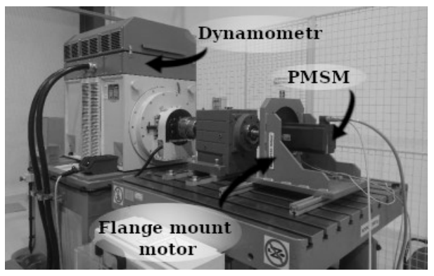
The view of the experimental bench is shown in Fig. 3. The performed bench enables the test to all types drive-motors applied in designed tower crane. In case of the slewing drive and the trolley travelling drive the brake operation during lowering of weight have been investigated.

In order to automate the measurements process, an algorithm allows saved discrete values of electromagnetic torque, phase currents, rotational speed and acceleration to CSV files was developed. Communication with the dynamometer controller is carried out using the Ethernet interface and the Modbus TPC protocol. The observations and saving of the measurement data is performed in real-time system during the algorithm work cycle.
Results of measurements
The selection of the electrical components of the hoist and slewing drive and trolley drive was made based on the Beckhoff software and the given working conditions (speed, load). As part of the research work, simulation calculations were made to verify design assumptions. On the basis of results of simulation calculation and our experience the proper drives were proposed. In the table 1 the rated parameters of servo-drive for hoist winch drive are listed.
Table 1. The rated parameters of the Beckhoff AM30833T40 motor

In experimental tests on the suitability of selected PM motors to crane applications, a trapezoidal motion profile was used. The motion profile determines changes of the velocity during single crane’s working cycle. The motion profile is used to calculate the values of the loading mechanical torque and enables the proper selection of the motor-drive. The visualization of the courses velocity, acceleration and position during the trapezoidal profile of motion is shown in Fig. 4. In case of a trapezoidal profile, a single working cycle consists of three stages: (a) the acceleration stage, (b) the constant speed operation stage and (c) the braking stage.

A. Analysis for the first type of load
As a first was performed experimental test simulating weight lifting at speed equal 1200 rpm with given load torque equal 150 Nm. It was assumed that single working cycle consist working time equal two minutes and break time equal three minutes. The measured waveforms of speed and torque are presented in Fig. 5.
Additionally, the waveform of output mechanical power during enforced duty cycle with load torque equal 150 Nm has been observed. On the basis of the mechanical power waveform (Fig. 6), the average mechanical power during a single duty cycle was calculated.
Next the waveforms of supply voltages and currents of propulsion system have been measured [17]. The waveforms of three line supply voltage (u1, u2 and u3) and supply line currents (i1 and i2) are presented in Fig. 7.
On the basis of the waveforms of voltages, currents and mechanical power of the servo-drive for hoist drive the functional parameters were calculated. The values of electrical parameters are listed in Table 2.

The efficiency of hoist winch drive system was calculated as follows:

where Pm is the mechanical power of hoist system, Pe is the total electrical power consumed by the hoist system.
Energy conversion efficiency for the host drive system calculated on the basis of presented measurements is equal 70.129%.
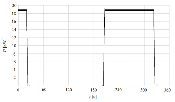

Table 2. The results of the electrical measurements for hoist winch drive system

B. Analysis for the second type of load
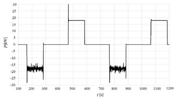
In order to accurately determine the parameters and properties of the propulsion system for hoist winch measurements for lifting and lowering the load have been performed. The following parameters have been assumed: the loading torque equal 135 Nm and rotational velocity equal 1280 rpm. In such case the single working cycle consist of: (a) two minute of working time and (b) three minute of break time. The Fig. 8 illustrates the waveform of mechanical power measured on the shaft of the motor drive.
In this case, the functional parameters of the servo-drive for hoist drive are presented in the Table 3.
Table 3. The results of the electrical measurements for hoist winch drive system during second type of load

For second studied case, the energy conversion efficiency for the host drive system calculated on the basis electrical and mechanical parameters is equal 88.045%.
Conclusions
The paper presents an application of the permanent magnet synchronous motors as a motor-drive to tower cranes. Based on the calculation and computer simulations, the proper motors were selected to relevant systems of the hoist winch drive. In the first stage of our project, the commercially produced PM motors were applied in constructed device.
The test bench for measurement functional parameters of the selected machines was built. The test bench allowed to modeling different waveform of load torque. Using the experimental bench the functional parameters of the propulsion system of hoist winch drive have been determined.
In the future research it is planed designing a new generation of energy-saving motors for cranes applications. In optimal designing process will be applied new nondeterministic methods of optimization from group of nature inspired algorithm. Moreover the guidelines for the optimal selection of electric motors and parameterization of the power supply control will be elaborated.
Acknowledgments: This work has been financially supported by the project No. POIR.01.01.01-00-1220/17.
REFERENCES
[1] Mitrovic N., Kostic V., Petronijevic M., Jeftenic B., Multi-motor drive for crane application, Advances in Electrical and Computer Engineering, vol. 9, no. 3, pp. 57 – 62, 2009.
[2] Belmans R., Bisschots F., Trimmer R., Practical design considerations for braking problems in overhead crane drives, Annual Meetings of IEEE Industry Applications Society – IAS, vol. 1, pp. 473 -479, 1993.
[3] Knypiński Ł, Jędryczka C., Demenko A., Influence of the shape of squirrel cage bars on the dimensions of permanent magnets in an optimized line-start permanent magnet synchronous motor, COMPEL, vol. 36, no. 1, pp. 298 – 308, 2017.
[4] Zawilak J., Zawilak T., High efficiency permanent magnet synchronous motor, Przegląd Elektrotechniczny, R. 90, no. 1, pp. 224 – 226, 2014.
[5] Knypiński Ł, Nowak L., Field-circuit simulation of the dynamics of the outer rotor permanent magnet brushless DC motor”, COMPEL, vol. 30, no. 2, pp. 929 – 940, 2011.
[6] Agamloh E. B., Cavaqgninio A., High efficiency design of induction machnies for industrial applications, IEEE Workshop of Electrical Machines Design, Control and Diagnostics – WEMDCD’2013, DOI: 10.1109/WEMDCD.2013.6525163.
[7] Król E., Permanent magnet synchronous motor and induction motor – factors decreasing the efficiency (in polish), Zeszyty Problemowe – Maszyny Elektryczne, nr. 80, s. 223 – 226, 2008.
[8] Barański M., Demenko A., Łyskawiński W., Szeląg W., Finite element analysis of transient electromagnetic-thermal phenomena in a squirrel cage motor, COMPEL, vol. 30, no. 3, pp 832 – 840, 2011.
[9] Knypiński Ł., Optimal design of the rotor geometry of linestart permanent magnet synchronous motor using the bat algorithm, Open Phisycs, vol. 15, no. 1, pp. 965 – 970, 2017.
[10] Awah C. C., Okoro O. I. , Chiukuni E., Coggging torque and torque ripple analysis of the permanent magnet fluxswitching machine having two stators, Archives of Electrical Engineeering, vol. 68, no. 1, pp. 115-133, 2019.
[11] Zhang Haifeng, Dong Zhi, Zhou Jinghua, Optimization design and analysis of permanent magnet synchronous motor based on VC, The Proceedings of International Conference on Electrical Machines and Systems, DOI: 10.1109/ICEMS.2017.8055957, 2017.
[12] Sorgdrager A. J., Wang R., Grobler A. J., Multiobjective design of line-start PM motor using the taguchi method, IEEE Transactions on Industry Applications, vol. 54, no. 5, pp. 4167 – 4176, 2018.
[13] Meng Y., Meng X., Design and implementation of a PMSM servo drive systems append to intelligent patrol robots, Materials Science and Engineering, vol 397, pp. 1 – 9, doi: 10.1088/1757-899X/397/1/012064, 2018.
[14] Backstrand J. E., The application of adjustable frequency drives to electric overhead cranes, DOI: 10.1109/IAS.1992.244208, 1992.
[15] Gwoździewicz M., Zawilak J., Limitation of the torque ripple in medium power line-start permanent magnet synchronous motor, Przegląd Elektrotechniczny, R. 93, no. 6, pp. 1- 4, 2017.
[16] Geng S, Zhang Y., Qiu H., Yang C., Yi R, Influence of the harmonic voltage coupling on torque ripple of permanent magnet synchronous motor, Archives of Electrical Engineering, vol. 68, no. 2, pp.399 – 410, 2019.
[17] Bugała A., Bednarek K., The use of computer simulations and measurements in determining the energy efficiency of photovoltaic installation, ITM Web of Conferences, vol. 19, 01021, 2018.
[18] https://www.krupinskicranes.com/
[19] https://www.konecranesusa.com/industries/automotive/craneautomation-for-the-automotive-industry
Authors: dr inż. Łukasz Knypiński, Poznan University of Technology, Institute of Electrical Engineering and Electronics, Poznań, Poland, e-mail: lukasz.knypinski@put.poznan.pl, mgr inż. Jacek Krupiński, Krupinski Cranes Sp. Z o.o., ul. Obywatelska 2A, 80-259 Gdańsk, j.krupinski@krupinskicranes.com
Source & Publisher Item Identifier: PRZEGLĄD ELEKTROTECHNICZNY, ISSN 0033-2097, R. 96 NR 1/2020. doi:10.15199/48.2020.01.07
