Published by Paweł WĘGIEREK, Michał LECH, Lublin University of Technology, Faculty of Electrical Engineering and Computer Science
Abstract. The article presents the detailed construction and capabilities of a research station for the diagnosis and testing of vacuum interrupters used in medium voltage electrical switching devices. The correct functioning of the stand has been confirmed by conducting a number of tests on the electrical strength of the MV switchgear vacuum interrupter type HVKR 24/400.
Streszczenie. W artykule przedstawiono szczegółową budowę oraz możliwości stanowiska badawczego służącego do diagnostyki oraz badań komór próżniowych wykorzystywanych w elektroenergetycznej aparaturze łączeniowej średniego napięcia. Poprawność funkcjonowania stanowiska potwierdzono przeprowadzając szereg badań wytrzymałości elektrycznej próżniowej komory rozłącznikowej SN typu HVKR 24/400. (Stanowisko badawcze przeznaczone do badań i diagnostyki komór próżniowych średniego napięcia).
Keywords: vacuum interrupters, vacuum diagnostics, dielectric strength, vacuum switchgears
Słowa kluczowe: komory próżniowe, diagnostyka próżni, wytrzymałość elektryczna, próżniowa aparatura łączeniowa
Introduction
Power engineering is a field of economy developing at a surprisingly fast pace. Many factors influence this process. One of them is the constantly growing number of new electricity consumers, and thus increasing the power required in areas that have not been urbanized before. According to the Transmission System Development Plan, by 2030 [1] the total net electricity demand in 2040 will be 204.2 TWh with 159.9 TWh in 2020.
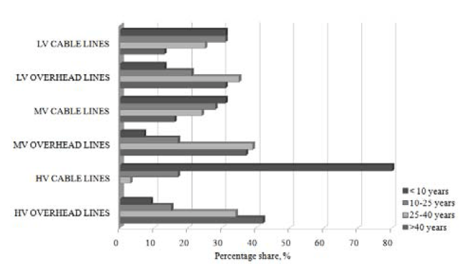
Another factor in the development of the Polish power industry is its current technical condition (Fig. 1). Outdated elements of the power infrastructure force the investments of power companies related to various types of modernizations [2, 3]. A particular problem is visible in the area of high and medium voltage overhead lines, over 75% of which were built more than 25 years ago [4]. MV power lines are one of the most important elements of the distribution system for both technical and economic reasons [5].
Another factor enforcing the dynamic development of the power industry is a number of legal requirements imposing on power companies to improve their power supply conditions and to move away from equipment using environmentally harmful greenhouse gases [6-11].
The above factors show that there is a strong need to develop new solutions among power equipment, mainly medium voltage. Many companies and scientific entities have faced this problem and developed pro-ecological equipment, using vacuum as an insulating medium.
One of such devices is the innovative EKTOS vacuum switch disconnector, which is the final result of the project entitled: “Development and implementation of an innovative closed cased overhead vacuum switch disconnector dedicated to intelligent medium voltage networks”, carried out by the Lublin University of Technology in consortium with EKTO Sp. z o.o. from Białystok as part of the activities of the National Research and Development Centre. This device is addressed to Distribution System Operators (DSOs) who want to improve the reliability of electricity supply in the areas they manage through investments in new technologies [12].
Methods for diagnosing vacuum conditions
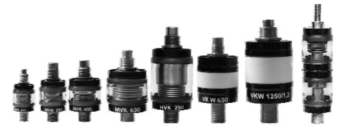
Equipment such as contactors, switches and disconnectors with installed vacuum interrupters are commonly used in the power industry. The ever-increasing number of such devices is directly related to the need for an effective diagnosis of the state of vacuum inside them. A number of existing diagnostic methods are used for this purpose to assess the proper functioning of medium voltage vacuum extinguishing interrupters in terms of dielectric strength. Examples of vacuum interrupters used in switchgear are shown in Figure 2.
The basic ones include: the Pening method and the Magnetron method [14, 15]. They consist of placing the tested chamber in a magnetic (strongly axial) field, and then applying a DC voltage of 10 ÷ 20kV to open contacts. According to the gas breakdown mechanism, due to the electric field created due to the applied voltage, electrons are emitted from the cathode moving towards the anode. Placing the chamber under test in the magnetic field changes the path of electrons motion into a spiral one, thanks to which the number of collisions with atoms and molecules of residual gas increases. The mentioned methods consist in recording the current of electron emission, which results from the collision ionization occurring in the chamber. In order to assess the vacuum condition, the characteristics determined for the new vacuum chamber must be known for further comparison.
Another method of diagnosing the state of vacuum is the static AC ignition voltage method [14, 16]. It consists in measuring the value of the jump voltage and then comparing it with the Pashen curve for a given chamber.
The static DC ignition voltage method, which is relatively simple, can also be used to check the correct operation of vacuum chambers. It consists in applying a certain voltage value to the chamber in the open state and then measuring the current value in the chamber and comparing it with the maximum allowable value [14, 17].
In high-frequency test systems, a frequently used method of diagnosing the vacuum condition is the method of AC current switching capability [14, 18], consisting in determining the ability to switch off the AC current, which clearly decreases at certain pressure values.
The Fowler-Nordheim dependence is often used for vacuum chamber tests [14, 19]. This method was called the emission current test method [14, 20]. The use of this method requires appropriate testing equipment, allowing the application of high DC voltage to the chamber, as well as measuring equipment enabling the measurement of currents at the microampere level.
A similar method to the one described above is the test method for emission currents with HF current surges [14, 17]. It consists in forcing a high current value of the frequency exceeding 1 kHz to flow through the chamber, which smoothes the contact surfaces of the chamber being diagnosed.
An interesting method of diagnosing the vacuum condition is the measurement of X-ray radiation [14, 18, 20]. The analysis uses the fact of proportionality of its intensity to the emission current. This method is characterized by a significant defect, consisting of interference from background radiation, which is greater than the radiation of the chamber under operating conditions, so that the results can be significantly disturbed.
Another method consists in measuring the arc voltage at direct current of 10A (DC arc voltage method) [14, 20]. This voltage increases its value while extinguishing the electric arc, while it decreases its value while developing new cathode spots associated with, among others with residual gas in the chamber. The higher the value of the peak voltage, the lower the pressure in the tested chamber.
The method based on measuring the value of the voltage initiating the micro-discharge and the voltage initiating the emission current, called the Vd/Ve method, uses the dependence about the inverse of these voltages in relation to the pressure inside the chamber [14, 21].
For vacuum chambers with external access to their screen, a method of measuring the screen potential can be used to assess the vacuum. It uses the phenomenon of changing the chamber screen potential under the influence of emitted electrons from the chamber contacts [14, 22].
Another method is the method of switching off low induction current, which consists in applying overvoltage impulses to the chamber’s contacts and using the phenomenon of power surges [14, 22].
The method of switching off capacitive current is implemented by breaking the circuit in which the capacitive current flows in the oscillating system [14, 22]. Then, the value of voltage appearing at the terminals of the tested chamber is used to assess the state of the vacuum.
There is also a diagnostic method of vacuum chambers based on the measurement of partial discharges that appear in the chamber during operation. However, the effectiveness of this method is visible at high pressures, which indicate complete leakage of the chamber [14, 22].
Test stand
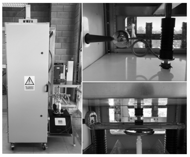
This test stand for the diagnosis and testing of vacuum interrupters used in medium-voltage switchgear has been designed and manufactured on the basis of a stable, mobile construction with a special platform used for the foundation of the vacuum pump set (Fig. 2). Inside the stand there is space for mounting the research object – medium voltage vacuum interrupter. The desire for a comprehensive study of the electrical strength of the vacuum interrupter is associated with the need to be able to change the contact distance in the appropriate range and with appropriate accuracy. In this test stand it was realized by mounting an extraction screw with a 1 mm pitch thread. Thanks to this, with the use of an appropriate reference scale, it is possible to set the inter-contact distance with the accuracy of 0.1 mm.
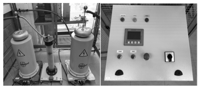
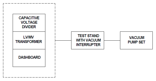
Power supply to the test stand is provided by means of YHAKXS 1x120mm2 power cable terminated with an angular connector head enabling quick and convenient connection of power supply to the test stand. The test set consists of three main elements: high voltage transformer, capacitive measuring divider and control panel (Fig. 3).
The nominal parameters of the kit are shown in Table 1. The schematic diagram of the complete test stand is shown in Figure 4.
An important element of the test stand is a vacuum set to obtain the appropriate pressure inside the vacuum interrupter to be tested. This is done by a set consisting of a turbomolecular and rotary vacuum pump operating at a capacity of 90 l/s.
Table 1. Rated parameters of the test set

Research facility
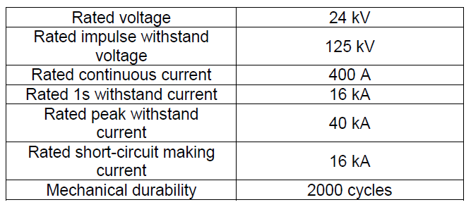
In order to verify the correct operation of the test stand, a test object was installed in it, which is the HVKR 24/400 vacuum disconnector interrupter (Fig. 5). Interrupters of this type are used in three-pole medium-voltage switch disconnectors operating in overhead power networks. Rated parameters of the interrupter are shown in Table 2.
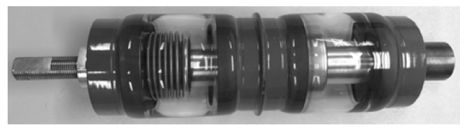
Table 2. Rated parameters of the HVKR 24/400 chamber
The above vacuum interrupter consists of two poles: mobile and fixed, with contacts made of a mixture of tungsten and copper at a ratio of 70% tungsten to 30% copper. An inseparable element of the interrupter is an elastic bellows enabling the movement of the moving pole, as well as a condensation screen catching conductive particles which, if deposited on the interrupter casing, would deteriorate its operating parameters.
Verification of the correctness of the position
Using the test stand described in this article, it is possible to diagnose the vacuum condition of the selected switch extinguishing interrupter. It is necessary to know its reference electrical strength characteristics and then to compare it with the obtained test results.
Verification of the correctness of operation of this method, called as a static AC ignition voltage method, was carried out in laboratory conditions for the contact distance in the range of 1 ÷ 5 mm for pressure from 4×10⁻⁴ ÷ 1.2×10³ Pa. The test results are presented in Figures 6 and 7.
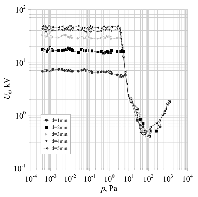
When analysing the above characteristics, attention should be paid to the pressure range in which the dielectric strength of the inter-contact interval of the vacuum interrupter under test is kept constant (Figure 6). This creates a certain safety zone which guarantees the reliable operation of a given device with respect to the electrical strength of the vacuum interrupter installed in it. This situation occurs below a pressure of . 5×100 Pa. The recorded breakthrough voltages in this zone are listed in Table 3.
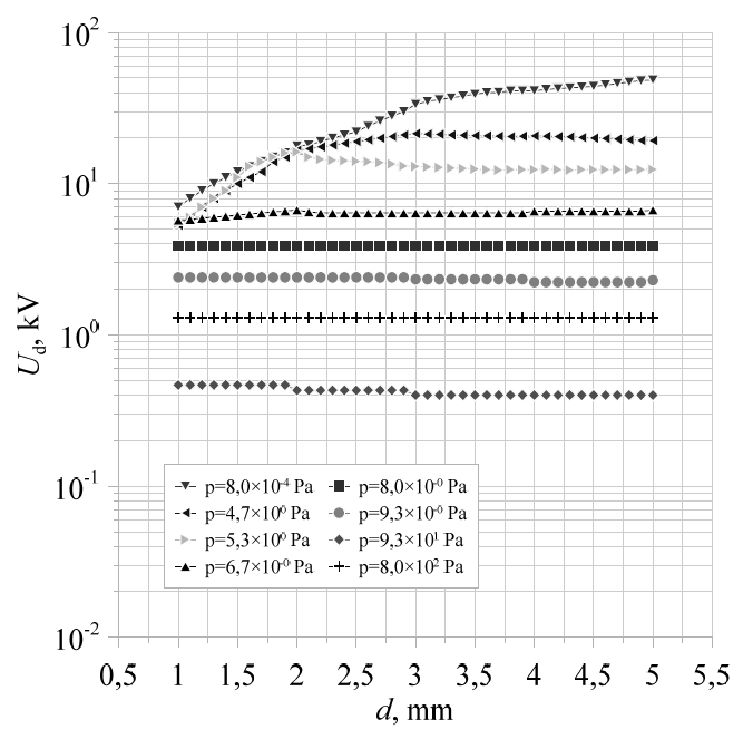
As the pressure in the tested interrupter increases, a sharp drop in strength is visible. Figure 7 shows the dependence of the breakthrough voltage of the tested vacuum interrupter on the contact distance for selected interrupter pressure values. For pressures between 8,0×10⁻⁴ ÷ 5.3×10⁻¹ Pa, the breakthrough voltage increases with the increase in the inter-contact distance. When the interrupter is further aerated, the characteristics are flattened. From the pressure value equal to 6.7×100 Pa, the contact distance did not influence the dielectric strength of the electrical interruption. A vacuum interrupter to be diagnosed, for which the measured value of dielectric strength would be within this range, would be diagnosed as defective.
Table 3. Values of breakthrough voltages recorded in the safety zone of the vacuum interrupter under test

Summary
The test stand presented in this article provides an opportunity to diagnose standard vacuum interrupters used in medium-voltage switchgear as well as to test them for improvement of operational parameters.
In order to verify the correct operation of the presented test stand, a number of tests were performed and graphical relationships between the selected parameters were obtained. On the basis of the obtained test results, it can be concluded that the stand described in the article was properly designed and made, and thus it is possible to use the static AC ignition voltage method.
The nearest research works will concern the improvement of electric parameters of vacuum interrupters by increasing the electrical strength of the inter-contact break, as well as limiting the negative effects related to the burning process of the electric arc of the inter-electrode space. The research will be supported by modern computer software enabling professional simulation of physical phenomena taking place in vacuum interrupters used in modern medium voltage electrical apparatus.
This work was supported by The National Centre for Research and Development and co-financed from the European Union funds under the Smart Growth Operational Programme (grant # POIR.04.01.04-00-0130/16).
LITERATURE
[1] Development plan for meeting current electricity demand for 2021-2030, Konstancin – Jeziorna, 2020
[2] Łukasik Z., Kozyra J., Kuśmińska-Fijałkowska A.: Monitoring of low voltage grids with the use of SAIDI indexes, Przegląd Elektrotechniczny, 10/2017, p.141-145
[3] Marzecki J.: Modernization and development directions of low and medium voltage rural network, Przegląd Elektrotechniczny, 2/2019, p. 67-70
[4] Power engineering, distribution and transmission, Polish Power Transmission and Distribution Associaton’s Report, Poznań, 2017
[5] Chojnacki A. Ł.: Comparative analysis of indicators and reliability properties of medium voltage overhead and cable power lines, Przegląd Elektrotechniczny, 11/2019, p. 26-30
[6] Konarski M., Węgierek P.: The use of Power restoration systems for automation of medium voltage distribution grid, Przegląd Elektrotechniczny, 7/2018, p. 167-172
[7] Montreal Protocol on Substances that Deplete the Ozone Layer, Montreal, 1987
[8] Kyoto Protocol to the UN Framework Convention on Climate Change, Kyoto, 1997
[9] Regulation (EU) No 517/2014 of the European Parliament and of the Council of 16 April 2014 on fluorinated greenhouse gases
[10] Quality Regulation 2018 – 2025 for Distribution System Operators
[11] Ordinance of the Minister of Economy of 4 May 2007 on detailed conditions of the power system operation
[12] Węgierek P., Staszak S., Pastuszak J.: EKTOS – innovative medium voltage outdoor vacuum disconnector in a closed housing dedicated to the network smart grids, Wiadomości Elektrotechniczne, 11/2019, p. 21-25
[13] http://www.repo.itr.org.pl/energetyka/vc.html, access:18.06.2020r.
[14] Chmielak W.: Review of methods of diagnostics of the vacuum in vacuum circuit breakers, Przegląd Elektrotechniczny, 2/2014, p.213-216
[15] Kuhl W., Schilling W., Schlenk W.: Messung des lnnendruckes in Vakuumschaltróhr, Vakuum-Technik 34. Jahrgang . Heft 2/85 Seite 34 bis 38
[16] Damstra G. C.: Pressure Estimation in Vacuum Circuit Breakers, IEEE ‘Trans. on Dielectrics and Electrical Insulation Vol. 2 No.2, April 1995
[17] Frontzek F.R., Konig D.: Measurement of Emission Currents Immediately After Arc Polishing of Contacts, IEEE Trans. on EI, vol. 28,No. 4, 1993, p. 700-705
[18] Frontzek F.R., Konig D., Methods for internal pressure diagnostic of vacuum circuit breakers, IEEE 18th ISDEIV – Eindhoven-1998, p. 467-472
[19] Kamarol M., Ohtsuka S., Hikita M., Saitou H., Sakaki M.: Determination of Gas Pressure in Vacuum Interrupter Based on Partial Discharge, IEEE Transactions on Dielectrics and Electrical Insulation Vol. 14, No. 3; June 2007, p. 593 – 596
[20] Walczak K., Janiszewski J., Mościcka-Grzesiak H.: Evaluation of internal pressure of vacuum interrupters based on dynamics changes of electron field emission current and X-radiation HV, Eng. Symp. Aug. 1999
[21] Ziyu Z., Shuheng D., Xiuchen J., Naixiang M., Liwen L., Huansheng S., Chongfang L.: Measurement of Internal Pressure of Vacuum Tubes by Micro-discharge and Emission Current XXIII-rd ISDEIV – Bucharest – 2008
[22] Damstra G.C., Merck W.F.H., Bos P.J., Bouwmeester C.E.: Diagnostic Methods for Vacuum State Estimation, IEEE 18th ISDEIV-Eindhoven-1998, p. 443-446
Authors: dr hab. inż. Paweł Węgierek, profesor uczelni, mgr inż. Michał Lech, Politechnika Lubelska, Wydział Elektrotechniki i Informatyki, ul. Nadbystrzycka 38A, 20-618 Lublin, E-mail: p.wegierek@pollub.pl, m.lech@pollub.pl.
Source & Publisher Item Identifier: PRZEGLĄD ELEKTROTECHNICZNY, ISSN 0033-2097, R. 97 NR 2/2021. doi:10.15199/48.2021.02.36
