Published by Rachid Dehini1, Ryma Berbaoui, Othmane Abdelkhalek, Electrical engineering Department, University of Tahri Mohamed. B.P 417 BECHAR (08000), Algeria. ORCID: 1 https://orcid.org/0000-0002-8769-218X
Abstract. This paper deals with the active and reactive power flow analysis inside the unified power quality conditioner (UPQC) during several cases. The UPQC is a combination of shunt and series active power filter (APF). It is one of the best solutions towards the mitigation of voltage sags and swells problems on distribution network. This analysis can provide the helpful information to well understanding the interaction between the series filter, the shunt filter, the DC bus link and electrical network. The mathematical analysis is based on active and reactive power flow through the shunt and series active power filter, wherein series APF can absorb or deliver the active power to mitigate a swell or sage voltage and in the both cases it absorbs a small reactive power quantity whereas the shunt active power absorbs or releases the active power filter for stabilizing the storage condenser’s voltage in addition to the power factor correction. The voltage sag and voltage swell are usually interpreted through the DC bus voltage curve. These two phenomena are introduced in this paper with a new interpretation based on the active and reactive power flow analysis inside the UPQC. For the digital simulation is supposed a linear load for the purpose of simplifying this study. The simulation results are carried out to confirm the analysis done.
Streszczenie. W niniejszym artykule omówiono analizę przepływu mocy czynnej i biernej wewnątrz zunifikowanego kondycjonera jakości energii (UPQC) w kilku przypadkach. UPQC to połączenie bocznika i szeregowego aktywnego filtra mocy (APF). Jest to jedno z najlepszych rozwiązań w zakresie łagodzenia problemów z zapadami i wzrostami napięcia w sieci dystrybucyjnej. Ta analiza może dostarczyć informacji pomocnych w zrozumieniu interakcji między filtrem szeregowym, filtrem bocznikowym, łączem szyny DC i siecią elektryczną. Analiza matematyczna opiera się na przepływie mocy czynnej i biernej przez bocznikowy i szeregowy filtr mocy czynnej, w którym szeregowy filtr mocy APF może absorbować lub dostarczać moc czynną w celu złagodzenia wzrostu napięcia i w obu przypadkach pochłania niewielką ilość mocy biernej, podczas gdy moc czynna bocznika absorbuje lub zwalnia aktywny filtr mocy w celu stabilizacji napięcia kondensatora akumulacyjnego oprócz korekcji współczynnika mocy. Zapad i wzrost napięcia są zwykle interpretowane przez krzywą napięcia szyny DC. Te dwa zjawiska zostały przedstawione w niniejszym artykule z nową interpretacją opartą na analizie przepływu mocy czynnej i biernej wewnątrz UPQC. W symulacji cyfrowej zakłada się obciążenie liniowe w celu uproszczenia tego badania. Wyniki symulacji są przeprowadzane w celu potwierdzenia przeprowadzonej analizy. (Analizy rozpływu mocy i stabilności systemu UPQC zintegrowanego z siecią dystrybucyjną.)
Keywords: UPQC, Power flux analysis, shunt filter, series filter.
Słowa kluczowe: rozpływ mocy, stabilność systemu, filtr bocznikpowy
Introduction
Actually, the low costs of power electronic devices has led to the wide spread increase of power electronic loads in industry [1-2-3]. As a result the significant non-linear loads, mass inductive loads and sensitive loads appear in a considerable amount of harmonics injection, low power factor and voltage disturbances in power systems. They tend to introduce voltage sag/swell, flicker, harmonics and asymmetries at the point of common coupling (PCC) [4]. These instabilities cause devices malfunctioning, overheating of power factor correction condensers, motors, transformers and cables. In addition, sensitive loads may not tolerate sags and/or swells and the electrical energy distributor may penalize low power factor at the PCC [5].
Customers describe equipment tripping resulting from perturbation in the supply voltage as “poor power quality”.
Specific devices are used as solutions for immediate treatment of each individual problem, such as using the Shunt APF to absorb the current harmonics [5-6], and Series APF to mitigate the voltage harmonics [6]., and using the DVR to adjust the sensitive load voltage at the time when the sag and swell voltage occur [5], and using the SVC to generate the reactive power for the load [8]. However these power quality problems usually occur in the system simultaneously and the use of these specific devices for each problem is not a cost effective solution. To dealing with all these problems simultaneously, the Unified Power Quality Conditioner (UPQC) has elaborated to be one of the most comprehensive custom power solutions for power quality (PQ) issues [9].
The (UPQC) is a custom power device, which combines the series and shunt active power filters functioning together, integrating these two filters. On the DC side, the two filters are connected back-to-back sharing a common DC condenser [10]. The UPQC series component inserts a voltage in order to maintain the load terminals voltage at a certain level and sinusoidal form [9-10]. This voltage is proceeded from a voltage source inverter (VSI) operated under pulse width modulation (PWM). At the same time, the UPQC shunt component injects current in the AC system to compensate for current harmonics in the load current, as well as to correct the power factor of the supply side near to unity. Fig. 1 shows a basic system configuration of a general UPQC.
This paper interests with the active and reactive power flow analysis between UPQC and the system components during voltage sag and swell at steady state. Aim is to maintain the load bus voltage sinusoidal and at desired constant level in all operating conditions. This power flow analysis plays an important role to well understanding the relationship between the UPQC’s parts during the compensation of some problems.

The UPQC power flow study
The UPQC is controlled in such a way that the voltages across the load are always sinusoidal and equal to a desired value. Therefore, the voltage injected by the series active filter equals to the difference between the supply voltage and the ideal desired voltage across the load. The function of a shunt active filter is to maintain the DC bus voltage at a constant value and to compensate the reactive as well as distorting powers required by the load; hence, the network provides only the active power.
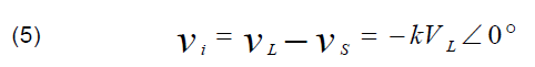
In what follows, the load voltage is considered in phase with the supply voltage. This is done by injecting a voltage in phase or in opposition phase with the source voltage respectively in cases of voltage sag or voltage swell, this leads to a bidirectional power flow (UPQC-Network) through the series active power filter (SAPF). The voltage injected by the SAPF must be positive or negative, according to the source voltage amplitude, voltage swell or sag. On account of this, the active power is absorbed or supplied by the SAPF. In this case the reactive power is fully compensated by the parallel active filter (PAPF).
In order to simplify this study, the load used has been assumed linear with a power factor equals 0.87. The equivalent UPQC single phase circuit is presented in the figure below.

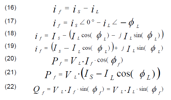
V is taken as phase reference and cos(ϕL) the power factor corresponding to the load, it can be said that :

Where k is the voltage fluctuation factor at the point of common coupling (PCC) A, defined by:

The inserted voltage by the series filter equals:
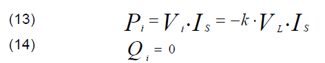
Supposing that UPQC is without losses, the active power required by the load equals that of the joining point. This power can be expressed as follows:

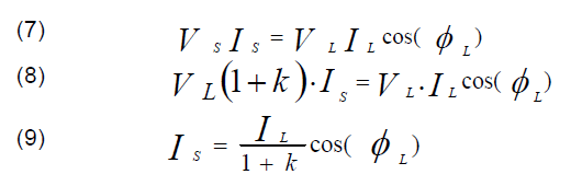
Equation (9) shows that the source voltage depends on both the k, cos(ɸL) factor and the load current IL.
The apparent power absorbed by the series filter can be written as:

Qi, the UPQC maintains the unit power factor on the load side:
The Power absorbed by the shunt active filter is:
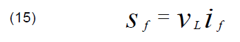
The voltage provided by the shunt active filter equals the difference between the source voltage and the load voltage including both harmonic and reactive voltages, thereby having:
Simulations and discuss
The structure group studied has been presented in the figure 1, but, in what follows, it should be noted that the load is assumed linear with a power factor which equals 0.87.
1. Biphasic voltage sag offset and power factor improvement
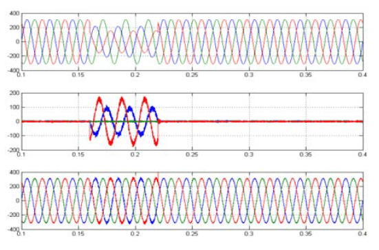


In this part the UPQC compensates in the same time the biphasic voltage sage and reactive power at PCC. Figure 3 illustrates that at the instant t = 0.16 sec and during 60 ms the phase (A) source voltage amplitude had been reduced by 30% while the phase (C) had been decreased with 50 % relatively to the fundamental voltage (220V) in such a way that the imbalance phase depth reaches almost 20% of the fundamental voltage (Figure 7-b) .While the load voltage is almost the same before, during and after the voltage sags. It is always kept to the same desired value (220V) (Figure 3-c), indeed, the imbalance voltage depth in this case does not exceed 0.4% of the fundamental voltage (Figure 7- a). This is due to the UPQC (series filter) which injects through the coupling transformer, the missing or compensatory voltages (Figure 3 – b).
At recovery supply voltage time, a slight disturbance happened during a very short time in both phases of compensated load voltage (Figure 3-c), synchronized with the time when the control adjusts the injected voltage characteristics at the new network situation.
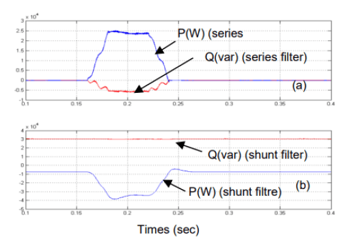
According to figure 5, the VDC voltage decreased at the voltage sag compensation. This decreased voltage across the condenser is explained by an active power offer from storage condenser to the network through the series filter (Figure 10 – a). At this time, the DC voltage control loop acts to compensate the energy shortage .This process causes an active power flow to the condenser from the network through the filter shunt (Figure 10 – b ) .Also that is appeared as an increase in the source current (Figure 4-c).

The figure 6 shows that during the normal operation, the power factor measured on the source side is very close to unity with an average value of 0.997, but at the voltage sag time, the reactive compensation quality is reduced with an average power factor value of 0.988, whereas that measured at the load side does not exceed 0.876.
As illustrated in figure 10-b, the reactive power average value measured from the source side, is still close to zero regardless of the perturbation imposed by the voltage sag. While the reactive power measured from the load keeps an almost constant value about 29.33 (kvar) (Figure 9 – a). It should be noted that during the voltage sag, the reactive power measured in both the network side and load side are slightly affected. Since during the disturbance time, the shunt filter conveys simultaneously two powers; the active power from the network towards UPQC for stabilizing the voltage across the condenser and also the reactive power from the UPQC to the load for improving the power factor.
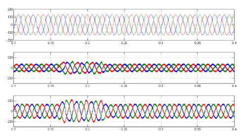
2. Biphasic voltage swell offset and power factor improvement

The power system undergoes a biphasic voltage swell during 60 ms with a depth of 70% and 30% on phase A and phase C respectively (Figure 11), where the unbalanced three phase depth measured in the source can reach 15% (Figure 15 – b). The series active filter begins instantaneously to compensate the voltage unbalance, and therefore the voltage imbalance depth on load side does not exceed 0.15% (Figure 15 – a).

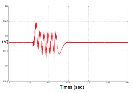
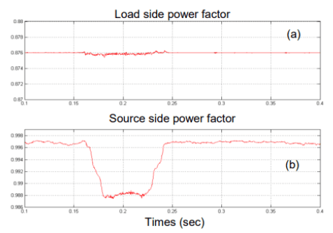


Figure 13 shows the voltage across the storage condenser that it overshoots its reference value (337.7 V) during the disturbance time. This phenomenon is interpreted by an active power excess due to an absorption of the active power from the network to the condenser through the series active power filter (Figure 18- a).Therefore, the DC bus voltage control loop always intervenes to stabilize the VDC value or balance the power flow in the storage condenser. Nearly the same amount absorbed by the series filter is simultaneously evacuated to the network with the shunt filter (Figure 18-b). During this correction, the source gives only the difference in amount energy required by the load. This is explained by a diminution in supply currents (Figure 12-c).
It is noted that the UPQC compensates the reactive power required by the load during all the processing. This is explained by the power factor measured on the source side which is very close to unity with an average value of 0.997, while it is reduced to 0.988 at disturbance time, (Figure 14).
As illustrated in figure 17 – b, the average value of the reactive power measured in the source side remains nearly equals zero though the disturbance imposed by the voltage imbalance. While the reactive power measured from the load almost keeps constant value about 29.33 kvar. It should be noted that during the voltage swell time, the reactive power is measured on the network side or load side are slightly affected since the shunt filter simultaneously transits two powers. In the voltage sag case; the active power had been transited from the UPQC to the network so as to stabilize the condenser voltage and also it transits the reactive power from the condenser to the load in order to improve the power factor.


Recapitulation
1. Normal operation
In normal operation, the UPQC compensates the load reactive power through the shunt filter while the series filter does not exchange any active or reactive power with the electrical network, the shunt filter power depends mainly on the injected current to the network, which depends on the load power factor and the harmonic currents in the case where the load is nonlinear.
2. Voltage sag case
In voltage sag case: VS<VL, and according to equation (4), where k <0, it signifies that the series filter injects an active power to electrical network (Pse) while the supply current raising (is) means the active power increasing that is absorbed by the parallel filter (Psh) with a view both to compensate the power injected by the series filter towards the load, and to keep the DC bus voltage to the desired value. On the other hand, at the voltage sag time, the UPQC absorbs reactive power (Qse) through the series filter and at all the time the UPQC compensates the load reactive power by injecting a reactive power (Qsh) through the parallel filter.
3. Voltage swell case
In voltage swell case: VS>VL, where k >0, it signifies that the series filter absorbs an active power (Pse) from the electrical network while the supply current decreasing (iS) means the active power increasing that is injected by parallel filter (Psh) with a view both to release the excess power in the DC bus condenser in order to stabilize its voltage value. Concerning the reactive power, during the voltage sag time, the UPQC absorbs reactive power (Qse) through the series filter. On the other hand, the UPQC compensates, during all the time, the load reactive power by injecting reactive power (Qsh) through the shunt filter.
Conclusion
For well understanding the functioning of the UPQC, an analysis of active and reactive power has been presented in this paper. Generally the UPQC is designed to compensate, sometimes, several disturbances at the same time. So it can compensate simultaneously such a voltage sage by the series filter and a reactive current through the shunt filter. As a result a new interpretation of the compensation phenomena for a voltage sage or swell with improving the power factor based primarily on an analysis of the power flow has been presented in this paper.
REFERENCES
[1] A.Amerise;M.Mengoni;G.Rizzoli;L.Zarri;A.Tani;D. Casadei, IEEE Transactions on Industry Applications, Volume: 56, Issue: 3, 2020, Page (s): 2762– 2772.
[2] R. Dehini, R. Berbaoui, , Revue Roumaine des Sciences Techniques Serie Electrotechnique et Energetiquethis, 2017, 62(4), pp. 346–351.
[3] M.Badoni;A.Singh;B.Singh, IEEE Transactions on Industrial Electronics Volume: 63, Issue: 5 , May 2016 , Page (s): 3028 – 3037.
[4] J.Kaniewski, Z.Fedyczak, P.Szcześniak, Przegląd Elektrotechniczny, ISSN 0033-2097, R. 91 NR 6/2015, doi:10.15199/48.2015.06.02.
[5] R.Dehini , A.Bassou , B.Chellali, PRZEGLĄD ELEKTROTECHNICZNY (Electrical Review), ISSN 0033-2097, R. 88 NR 4a/2012, Page (s): 289 – 292.
[6] H.Geng; Z.Zheng; T.Zou; B.Chu; A.Chandra, : IEEE Transactions on Industry Applications, Volume: 55, Issue: 3, May-June 2019, Page(s): 3198 – 3206.
[7] M. Rane, S. Wagh, HeliyonVol. 5Issue 2Published online: February 5, 2019, Page(s): 1 – 28, doi: 10.1016/j.heliyon.2019. e01178.
[8] A. Águila Téllez, G. López, I. Isaac , J.W. González, Heliyon,Vol. 4 Issue 8 Published online: August 22, 2018, Page(s): 1 – 30, doi: 10.1016/j.heliyon.2018.e00746
[9] S.Lakshmi ; S.Ganguly, IET Renewable Power Generation, ISSN 1752-1416, Vol. 12 Iss. 5,13th Feb 2018, Page(s): 605-613, doi: 10.1049/iet-rpg.2017.0525 http://www.ietdl.org.
[10] C.Karuppaiyah Sundarabalan ; Y.Puttagunta ; V.Vignesh , IET Smart Grid, Volume 2, Issue 1, March 2019, Page(s): 60 – 68, ISSN 2515-2947, DOI: 10.1049/iet-stg.2018.0148
Authors: prof. dr Rachid Dehini, Electrical engineering Department, University of Tahri Mohamed, B.P 417 BECHAR (08000), Algeria. E-mail: dehini_ra@yahoo.fr, Ryma Berbaoui, Email: ryma.ber@hotmail.fr, Othmane Abdelkhalek, Laboratory of Smart Grids and Renewable Energies, Tahri Mohammed University of Bechar, E-mail: abdelkhalek.othamane@univ-bechar.dz
Source & Publisher Item Identifier: PRZEGLĄD ELEKTROTECHNICZNY, ISSN 0033-2097, R. 98 NR 11/2022. doi:10.15199/48.2022.11.05
