Published by 1. Dnyaneshwar D. Ahire, Professor, Matoshri College of Engineering and Research Centre, Nashik Savitribai Phule Pune University, Nashik, Maharashtra, India.
2. Snehal R. Durdhavale Student, Matoshri College of Engineering and Research Centre, Nashik Savitribai Phule Pune University, Nashik, Maharashtra, India.
ABSTRACT – A load is said to be “linear” when it draws a current from the supply which is proportional to the applied voltage (linear). And in the case of “non-linear” load, impedance changes with applied voltage. The current drawn from such non-linear load is also non-linear i.e. non-sinusoidal even when it is connected to a sinusoidal voltage source. Harmonic currents contents which are present in non-sinusoidal currents intermingle with the impedance of the power distribution system to create voltage distortion which affects the distribution system and the loads connected to it. The serious power-line pollution is a result of increasing use of power electronic systems and time-variant nonlinear loads in industry. Hence, power supply quality is degraded. It results in the reduction of system efficiency, apparatus overheating, and increase power. As the utilization of the number of harmonics-producing loads has increased over the years, it has become highly mandatory their influence and analysis when making any additions or changes to an installation. In this paper various harmonics detection and measurement techniques have been outlined.
Keywords: Non-linear loads, harmonic currents, power distribution system, voltage distortion, power signal quality, harmonic distortion.
1. INTRODUCTION
Power quality can be defined as a set of electrical boundaries allowing an equipment to function in its intended manner with no significant loss of performance or life expectancy. Various methodologies and techniques were proposed to improve the power quality. A power system ideal when is define when a perfect sinusoidal voltage signal is seen at load-ends. Practically, such idealism is really hard to maintain. Any deviation from the perfect sinusoidal waveform is nothing but distortion and hence harmonic distortion. It has been said about harmonics is they are voltages or currents with frequencies which are integer multiples of the fundamental power frequency. Only odd harmonics will be produced by electrical equipment’s, when working in normal or no load condition. When transient conditions or conditions of mal-function or single-phase rectification appear, even harmonics may occur. One of the parameters which affect the quality of power is harmonics current are supplied by the non-linear equipment, which disrupts the desired linear system. These distorted current pulses, due to Ohm’s law, will also instigate to distort the voltage waveforms, where these distortions would be carried back to the distribution network. Common risks of harmonics include potential fire hazard, excessive heat, false tripping of branch circuit breakers and consequently increases maintenance cost [2], [3].
1.1 Basics
In any power system, it is highly impossible to accomplish a perfect or pure sinusoidal waveform at every point of a network. The voltage and current waveform deviate massively from a sinusoidal waveform. These waveform deviations are usually called harmonic distortion.
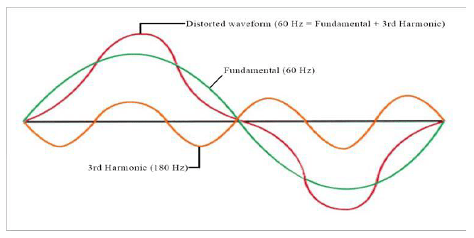
“Harmonics” is the term which means waves having frequencies of integer multiples of one another. The harmonic component in an AC power system is nothing but the sinusoidal component of a periodic waveform that has a frequency of an integer multiple of the fundamental frequency of the system. It can be given as:
fh= n*fundamental frequency
Where, fh= harmonic order, n= integer, and the fundamental frequency is either 50Hz or 60Hz.
For example, if a system has the fundamental frequency as 60Hz then its 2nd and 3rd harmonic would have frequencies of 120Hz and 180Hz respectively[1],[[2].
1.2 Classification of Harmonics
Harmonics which are nothing but distorted waveforms have two types namely voltage and current harmonics. The orders of harmonics and symmetrical components these are two concepts which are used commonly to describe harmonics. Regarding the harmonics, words odd and even harmonics are used usually but the term triplen harmonics is not much known. Table shows harmonic orders:
Table 1. Harmonic Orders

In the present scenario, odd harmonics are the characteristics harmonic components in the power network. Waveforms that are symmetrical to the time axis are represented by odd harmonics. In the case of even harmonics, they can only arise from waveforms that are not symmetrical to time axis [16].
1.3 Power Quality Indices under Harmonic Distortion
[16] Generally, representation of harmonic components is given with equation:

Where 𝑓𝑛= current amplitude of nth order harmonic, 𝑓1=fundamental current amplitude.
1.3.1 Total Harmonic Distortion (THD)
This notification is used widely in defining the harmonic content level. It is given as the ratio of the power of all harmonic components to the power of fundamental frequency.
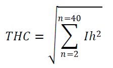
1.3.2 Total Harmonic Current (THC)
Usually, distorted current waveform is caused by the contribution of current orders 2 to 40. THC value is used for installation of active filters. It can be written as:
1.3.3 Total Harmonic Distortion Current (THDi)
This value gives the total harmonic distortion of the waveform. This value can be calculated by taking the ratio of THC to the Fundamental current. It can be given as:

Where 𝐼1= fundamental current
Where 𝑉𝑛= voltage amplitude of nth order harmonic, 𝑣1=fundamental voltage amplitude. For the sake of good voltage quality, its value should be low.
1.3.4 Total Harmonic Distortion of Voltage (THDv)
It shows the total magnitude of the distortion in voltage. It can be calculated by calculating ratio of distorted or harmonic voltage to the non-harmonic or fundamental voltage. It can be written as:

1.3.5 Total Demand Distortion (TDD)
This concept is used widely used in North America regarding harmonics. It is the ratio of harmonic current to the full load fundamental current. The full load current is nothing but the total non-harmonic current consumed by all loads by the system when the system is on its peak demand.

Where 𝐼𝑛= current amplitude of nth order harmonic, Il= total load current consumed by system
1.3.6 Partial Weighted Harmonic Distortion (PWHD)
PWHD is the ratio of current or voltage with selected group of higher order harmonics from 14 to 40 to the fundamental value of voltage or current. PWHD for current and voltage can be given as:
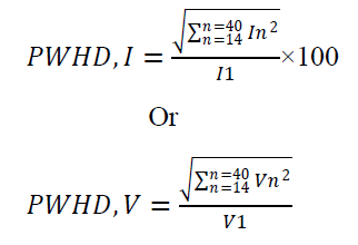
Where, 𝐼1= fundamental current amplitude, V1= fundamental voltage amplitude.
1.4 Sources of harmonic Distortion
There are many harmonics sources are present but out of them few are listed here which play a role as the major sources of harmonics [14],[16].
1.4.1 Static Compensators
If the power source is fluctuating, static compensators are used at the ends of transmission lines or near sources of fluctuating power, static compensators manage the voltage. Reactors which are controlled by Thyristor will produce near about 1% of the 11th harmonic current.
1.4.2 Power Converters
Rectifiers give higher inductance on the dc side compared to the ac side. Hence the dc current is almost constant and then converter starts acting as a harmonic voltage source on the dc side where as the harmonics current source on the ac side.
1.4.3 Transformer
Because of saturation and hysteresis characteristics, a small level of harmonic current will get produce by transformers when they are in steady state. Initially high level of harmonics will be produced, which is 60% of the rated transformer current.
1.4.4 Rotating Machines
In the rotating machines, harmonic currents can be produced due to asymmetries in the winding pattern. Harmonics grow because of the resultant magneto motive force in the machine. Due to magnetic core saturation harmonic currents are generated.
1.4.5 Electric Arc Furnace
As the arc feed material varies, the harmonics rise up and their value cannot be predicted certainly. The electric arc furnace load gives most awful distortions a result of melting with the moving electrode and molten material.
1.4.6 Switched Mode Power Supplies (SMPS)
Latest electronic devices contain switched mode power supplies. SMPS regulates AC or DC input voltage. SMPS unit draws current pulses contain large amount of harmonics of third and above higher order harmonics.
1.5 Effects of Harmonics
Harmonics affect the power equipment’s and components. Following effects are shown on different components [14], [16]:
1.5.1 Power Factor
Harmonic distortion affects the power factor. Power factor gets worse with increasing amount of harmonic distortion. Generally, non-linear loads result in poor power factor.
1.5.2 Electric and Electronic Equipments
Basically, these equipments are considered as a source of harmonics. These devices are sensitive to harmonic distortion. They show effects as increase in supply voltage, zero crossing noise, malfunction of protective devices etc.
1.5.3 Conductors
On a regular basis, heat will be generated in the current carrying conductors due to I2R losses. As the harmonic orders increase, skin effect is produced. As the skin effect increases more I2R losses cause over heating of the conductors. Heating of conductors may also occur because of the magnetic field of harmonic currents in the neighboring conductors.
1.5.4 Transformers
Frequency causes Eddy current losses. Hence, as the harmonic order increases eddy current losses for transformers also increase. In addition to the skin effect, eddy current losses in transformer fallout in overheating and the life of the transformer would be reduced.
1.5.5 Capacitance
The Capacitors improve the power factor. They have a significant influence on harmonic levels. As the frequency of harmonics increases, the capacitive reactance decreases. As increased flow of current increase, the capacitor may get congested and impose higher dielectric stress.
1.5.6 Circuit Breakers and Fuses
Low level faults in circuit breakers caused because of the high degree of harmonic load current. High 𝒅𝒊/𝒅𝒕 ratings at zero crossings for sinusoidal waveform make the disruption complex, for load distortion. Hence, harmonic load currents results in circuit failures.
1.5.7 Lights
The distorted power supply decreases the life of the lamp gets decreased with. Harmonic currents give problems to audible noise in the case of discharging of lamps. In equipped with capacitors, together with the ballast inductor and the lamp may form a resonance problem.
1.5.8 Rotating Machines
Operating frequency plays a vital role in losses produced in the electric machines. Core and stray losses become significant for induction motor for an inverter producing high harmonic frequencies. The increase in temperature in the windings causes the lessening of life of the rotating machines. Communication between the air gap flux density and the fluxes generated by the harmonic currents in the rotor, pulsating torques are produced. By reason of the difference between time harmonic frequencies audible noises are formed. Additional problems in rotating machines caused by harmonics are equipment failure, bearing wear out, etc.
1.5.9 Telephone Interferences
Fundamental frequency doesn’t cause any serious problems but power system harmonics can cause huge problems because human audible sensitivity and telephone response peak have near 1 KHz. Inductive, capacitive and conductive interferences can be occurred between telephone line and a power line.
1.6 Why Harmonics should get detected?
Basically, harmonics are difficult to reduce. But the power quality gets reduced because of harmonics. They show economic impacts such as earlier failure of equipments, losses in distribution systems. So, they should be detected at early stage.
2. LITERATURE REVIEW
Tremendous work has been done for harmonics, their analysis and various mitigation techniques of harmonics. A brief review on this: For the reliable and efficient operation of any system a properly designed electrical system is necessary. And the system should be harmonic free.
For this purpose, capacitors in harmonic environment are applied. They are beneficial because they result in minimized THD, improved power factor and elimination of power factor penalties [3]. Lucian Asiminoae, Sergej Kalaschnikow and Steffan Hansen have discussed two harmonic detection methods. The methods are selective harmonic compensation and overall harmonic compensation [4].
An innovative method is presented for measurement of individual harmonics of a time-varying frequency. This proposed method is based on a nonlinear, adaptive mechanism. This technique offers the higher degree of accuracy, frequency-adaptivity [5]. David M. McNamara, Alireza K. Ziarani presented a new method of measurement of harmonics of time-varying frequency. This proposed method is based on the adaptive evaluation of the fundamental frequency and its harmonic components of the power signal [6].
A system made from a combination of the ARM9 chip and virtual instrument technology is designed for a real-time harmonic measurement. This system is presented in the paper [7].Frequency is a significant factor for harmonics measurement. The paper contains a review of several commonly used methods for power system harmonics measurement. And those methods are compared according to the aspect of frequency identification [8]. This paper gives a new idea for harmonic detection adopting the algorithm with combination of FFT with and wavelet transform. This instrument can obtain parameters of harmonic [9]. Hsiung Cheng Lin developed a strategy of recursive group-harmonic power minimizing for system harmonic and interharmonic evaluation in power systems. The proposed algorithm can measure integer harmonic and the interharmonics also identified accurately [10].
Harmonic components and harmonic distortion can be calculated using distortion meter. This paper presents the harmonic distortion meter based on microcontroller and its software part carries out calculations using DFT. DFT is used to find amplitude in order to measure THD in power system [11]. In this review paper an author has discussed abundant for selective harmonic detection methods in frequency domain as well as in time domain like DFT, FFT, SOGI technique and CDSP-PLL systems [12]. To estimate the fundamental frequency and to measure both harmonics and inter harmonics of any unknown frequency is not an easy task. But using the adaptive notch filter this can be done. This methodology measures fundamental frequency and harmonic and inter harmonic components fast [13].
Usage of non-linear loads in power system results in poor power quality. These loads are leading to harmonic sources; and this has become much serious problem. One of the widely used algorithms for harmonic analysis is Fast Fourier Transform (FFT). In this project, a harmonic analyzer is implemented using FFT on ARM7 core processor (LPC2138). For matching power rating the supply voltage is divided to 6V using the voltage divider. This harmonic analyzer can analyze harmonics in single phase supply and gives frequency spectrum of harmonics. This system has the advantage of being available in at low cost [15].
A constant wave Terahertz spectrometer is integrated with 1X2 LiNbO3 which is fiber coupled and customized optical phase modulator which allows direct modulation of Terahertz (THz) beam and measurement of the 1st and 2nd harmonics of modulation. Thus, using optical phase modulation rather than bias modulation harmonics measurement is carried out [17].
We know that harmonics is a very basic property of power quality. So it has become necessary a thing to measure these harmonics. Instead of using traditional measurement device a new method to detect and measure harmonics is presented. This device consists of the analog to digital converter, FFT unit, LCD display unit, and network communication unit. This methodology adopts FPGA and DSP processor. Experimental results show that using presented device more accuracy is obtained and harmonic power flow is also analyzed [18].
3. PROPOSED WORK
The various harmonic mitigation strategies adopted in the last three decades have been reviewed. Based on this survey a new methodology to control harmonic distortion in power system is introduced. In the proposed method harmonics get detected using ARM7 core processor (LPC2478). The software side performs FFT calculations for getting the amplitude of the fundamental frequency and the nth order harmonic. The distortion is calculated using the ratio of the amplitude of measured harmonic to the fundamental frequency.
The benefits of the proposed optimization method are:
1. Detection of harmonics in easier way
2.Correct measurement of harmonics and THD
4. CONCLUSIONS
Non-linear loads result in harmonic distortions in the power system and the associated problems were discussed briefly. Comprehensive review related to various methodologies to detect and measure harmonics in power system that was mentioned in the literature is done. Based on this review a new hybrid optimistic method to detect and measure harmonics is introduced in this paper. The system is designed for detection and measurement of harmonics on ARM 7 platform. Proposed system uses FFT algorithm for measuring total harmonic distortion.
5. REFERENCES
[1] Harmonics Detection and Filtering, Low Voltage Expert Guides by Schneider Electric.
[2] Harmonics in Your Electric System, A White Paper of Eaton Corporation.
[3] Douglas Andrews, Martin T. Bishop, John F. Witte,(May-June 1996), Harmonic Measurements, Analysis, and Power Factor Correction in a Modern Steel Manufacturing Facility, IEEE Transactions on Industry Applications, Vol. 32, No. 3.
[4] Lucian As iminoae,, Sergej Kalaschnikow and Steffan Hansen, Two harmonic detection methods used in industrial shunt active filters
[5] Masoud Karimi-Ghartemani, and M. Reza Iravani,( January 2005), Measurement of Harmonics/Inter-harmonics of Time-Varying Frequencies, IEEE Transactions On Power Delivery, Vol. 20, No.3.
[6] David M. McNamara, Alireza K. Ziarani, Thomas H. Ortmeyer(January 2007), A New Technique of Measurement of Nonstationary Harmonics, IEEE Transactions On Power Delivery, Vol. 22, No.1
[7] Weicheng XIE, Xia YANG, (2010), A Power Harmonic Measurement System Based on Wavelet Packet Transform and ARM9, IEEE.
[8] Gary W. Chang, Senior Member, IEEE and Cheng-I Chen, (2010), Measurement Techniques for Stationary and Time-Varying Harmonics, IEEE
[9] Shouxi Zhu, Wenlai Ma, (2012), Design of Power Harmonic Detection Instrument Based on DSP and ARM, CISME Vol.2 No.2
[10] Hsiung Cheng Lin, (February 2012),Power Harmonics and Interharmonics Measurement Using Recursive Group-Harmonic Power Minimizing Algorithm, IEEE Transactions On Industrial Electronics, Vol. 59, No.2
[11] Jaipreet Kaur Bhatti, Deepak Asati, (June 2012), Harmonic Detection using Microcontroller, International Journal of Computer Technology and Electronics Engineering (IJCTEE) Volume 2, Issue 3.
[12] Yi Fei Wang,Yun Wei Li,(2013), An Overview of Grid Fundamental and Harmonic Components Detection Techniques, IEEE
[13] Zhaobi CHU, Ming DING, Shaowu DU, Xueping DONG, (2013), Normalized estimation of fundamental frequency And measurement of harmonics/interharmonics.
[14] Alexander Kamenka, (2014) Six Tough Topics about Harmonics Distortion and Power Quality Indices in Electric Power System, A White Paper of Schaffner Group.
[15] Jeena Joy, Amalraj P.M., Aswin Raghunath, Nidheesh M.N Vinu Joseph,(August 2014), Harmonic Analysis of 230 V AC Power Supply Using LPC2138 Microcontroller, Transactions on Engineering and Sciences ,Vol.2, Issue 8.
[16] Manish Kumar Soni, Nisheet Soni, (February 2014), Review of Causes and Effect of Harmonics on Power System , International Journal of Science, Engineering and Technology Research (IJSETR), Volume 3, Issue 2.
[17] J. R. Demers, B. Kasper1, D.R. Daughton, (2015), Simultaneous measurement of the 1st and 2nd harmonics of a phase modulated coherent frequency-domain THz spectrometer
[18] Feng Guihong, Zhang Jing, Zhao Yisong , Ying Yong, Zhang Bingyil, Harmonic Power Detection and Measurement Device Based on Harmonic Power Flow Analysis.
Source & Publisher Item Identifier: https://ijcaonline.org/archives/volume143/number10/durdhavale-2016-ijca-910394.pdf , International Journal of Computer Applications (0975 – 8887) Volume 143 – No.10, June 2016.
