Published by Laith A. Mohammed1, Taha A. Hussein2, Ahmed T. Sadoon3, Northern Technical University, Engineering Technical College of Mosul, Mosul, Iraq.
ORCID: 10000-0002-2882-2845; 2. 0000-0001-9516-6860; 3. 0000-0002-8440-6061
Abstract. In this paper, optimum switching angles are chosen from slime moiled algorithm (SMA), Artificial Bee Colony (ABC), Genetic algorithms (GA), Whale optimization algorithm (WOA), and Gray wolf algorithm (GWO). These angles are selected according to the lowest total harmonic distortion of output load voltage from reduced switches multilevel inverter. These algorithms are working together in a hybrid seduced to solve the nonlinear equation of switching angles determination. A 25-level inverter fed by isolated unequal PV panel as DC sources with reduced switches and sources is chosen for this study. Theoretical analysis and Simulation are accomplished using Matlab/Simulink for 25 level reduced switches multilevel inverter. The simulated results validated the practical outcomes.
Streszczenie. W niniejszym artykule optymalne kąty przełączania zostały wybrane spośród algorytmu śluzowatego (SMA), sztucznej kolonii pszczół (ABC), algorytmów genetycznych (GA), algorytmu optymalizacji wielorybów (WOA) i algorytmu szarego wilka (GWO). Kąty te są dobierane zgodnie z najniższymi całkowitymi zniekształceniami harmonicznymi napięcia obciążenia wyjściowego ze zredukowanych przełączników wielopoziomowych falowników. Algorytmy te współpracują ze sobą w hybrydzie, której celem jest rozwiązanie nieliniowego równania wyznaczania kątów przełączania. Do tego badania wybrano 25-poziomowy falownik zasilany przez izolowany nierówny panel fotowoltaiczny jako źródła prądu stałego o zredukowanych przełącznikach i źródłach. Analiza teoretyczna i symulacja są realizowane przy użyciu Matlab/Simulink dla 25 przełączników o zredukowanych poziomach wielopoziomowego falownika. Symulowane wyniki potwierdziły praktyczne wyniki. (Zwiększenie wydajności wielopoziomowych przełączników falownika do systemu fotowoltaicznego)
Keywords: Multilevel Inverter (MLI), slime moiled algorithm (SMA), minimizing THD, hybrid optimization algorithms.
Słowa kluczpowe: przekształtnik wielopoziomowy, algorytm SMA, hybryfowy algorytm optymalizacji
Introduction
Renewable energy deals with unlimited natural resources to produce energy. One of the most important types of renewable energies is solar energy, as it is considered free energy and is available all season in most countries with varying intensity. One of its most important advantages is that it is unlimited and does not increase pollution and global warming. The PV system has attractive features for generating power that matches the peak-load demand. Solar energy systems are one of the systems that dominate the commercial markets, as this efficient technology has been relied upon by up to 20% [1], the dc to ac converters are the main parts of the PV system. Multilevel inverters (MLI) are a very important device for converting power in a wide applications range, In recent decades, the rating power of energy generating and distribution networks has expanded significantly. [2].
Therefore, A high power demand using a high-power system is required.(MLI) with an appropriate topology to processing a high-power system for overcoming the limitation of the voltage rating of power switches [3], [4].
The MLI provides several advantages, including high-power quality signals, a transformer-free structure, lower switching losses, and reduced stress on power electronic switches. However, this technology is challenged by the determination of the switching angles it’s on certain applications and can be applied in Renewable Energy.
The growth of demand for electric energy has become very clear in recent years, as the number of devices, vehicles [5], [6], and industrial plants that use electric energy has increased. On the other hand, the rise in environmental pollution and climate change caused by fossil fuels and their approaching exhaustion, as well as high extraction and cost of transportation, has caused the world’s eyes to turn to renewable energies.
Many researchers work on MLI for improving THD by using optimization methods and upgrading new topologies. In 2012 [7], the Application of the Bee Algorithm for switching angles determination in Multilevel Inverters was presented, the Bee algorithm (BA) is applied to a 3-phase, 7-level inverter for solving the non-linear equations results in the THD of output voltage equal to 8.99%.In 2018[8], presents, a Selective harmonic elimination (SHE) in (MLI) using hybrid asynchronous PSO (APSO) algorithm presents (SHE-PWM) technique.
Based hybrid (APSO) Newton-Raphson (APSO-NR) algorithm for eliminating undesired harmonics in cascaded H-bridge (MLI) and the best THD was 12.52 % for phase output voltage. In 2017[9], a Hybrid.
An optimization algorithm was applied for low order harmonics elimination in reduced switches multilevel inverter, ant colony optimization-based hybrid algorithm was used to calculate the optimum switching angles in three-phase seven-level inverter, the THD of the load voltage obtained was 4.66% at M=0.8.Modulation Index. In 2020 [10], A Performance comparison between Newton Raphson (N-R) algorithm and genetic algorithm (G-A) was applied to calculate the switching angles for the 9-level asymmetric cascaded H-bridge inverter. The prototype with FPGA control shows the minimum THD of the output voltage was 10.9%. In 2015 [11], proposed three evolutionary algorithms for eliminating low order harmonics in, voltage source MLI, the ant colony optimization (ACO), particle swarm optimization (PSO), and real coded genetic algorithm (RCGA) was implemented and compared for calculating switching angles of an 11-level inverter. In 2015 [12], they used Real Coded Genetic Algorithm Approach for Harmonic Reduction in MLI, variable frequency and variable voltage for high power ac motor drive can be operated over a wide range of modulation indices. The lowest order harmonic is 13th while keeping the magnitude of the fundamental at the desired level. In this work, optimum switching angle calculation from Genetic algorithm, Slime moiled algorithm, Grey wolf algorithm, and Artificial Bee colony to drive MLI with reduced switches in a PV system.
Photovoltaic System
Solar energy is the world’s most plentiful renewable energy [13]. Because it is an endless and environmentally friendly energy source, the photovoltaic (PV) system is getting a lot of attention. It also has a lengthy lifespan due to its low maintenance requirements. But on the other hand PV system is affected by solar irradiation, temperature and it is extremely reliant on certain atmospheric conditions. [14–17]. PV cells which are formed of silicon, are used to build photovoltaic modules. thin films formed by the precipitation of a photosensitive material from crystalline silicon wafers.
Photovoltaic cells convert radiation energy into electrical energy immediately [18]. Each A photovoltaic cell is a simple p-n junction diode with a surface that is directly exposed to the sun.
When exposed to sunlight, charge carriers form, which produces electricity. The Basic Circuit diagram in Fig. 1. shows the basic elements of a PV cell [19] depicts a PV cell diagram.
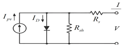
were:- Ipv: – represent the output current generated by the PV panel under standard climatic conditions of the temperature and the irradiation (T=25°C and Irr =1000W/m2); ID: – The saturation current; Rsh: – due to leakage current through the p-n junction; Rs: – due to the combined resistances of contacts, metal grids, and P and N layers
Multi-Level Inverter (MLI)
One of the effective types of Inverters in working with solar panels is the Multi-Level Inverter (MLI), the main types of which are Climbing Diode (CD-MLI), Flying capacitors, and Cascade Multi-Level Inverter (C-MLI) [20],[21].
Recent research on this type of inverters focuses on two main divisions: reducing the number of switches and the dc sources used through the continuous development of topologies, and the second branch on developing methods for controlling triggering angles to reduce harmonics resulting from the work of the inverter.
It is known that the number of eliminated harmonics is equal to the number of switching angles [23-25] and since the traditional method for calculating the switching angles is Newton Raphson (NR), which need an initial value of switching angles., which is the drawbacks of this method., the most important of which is that it needs initial guess values that are close to the correct solution, otherwise there will be diversions and errors and also works in a slight range of the modulation index (M).
In this topology, we will use four power sources (D.C) and eight unidirectional and bidirectional power switches. The benefit of this topology is that the peak switch voltage is reduced.
Although the 25-level layout decreases the number of switches count [26]
MLI has a low harmonics content profile due to its ability to synthesize an output voltage waveform from each inverter-level output voltage. This is will be suitable for the distributed energy resources where several batteries, solar cells, or micro turbines are required to be connected to the AC grid. Many switching strategies can be applied to control MLI output voltage magnitude, frequency, and harmonics content such as space-vector (SVPWM) [22] , Selective Harmonic Elimination Pulse Width Modulation (SHEPWM) techniques Among all them SHEPWM technique is the most commonly used technique in which tight harmonics profile can be achieved with wide control of the fundamental voltage component. [22]
Harmonic Elimination
For single-phase MLI, the output voltage may be expressed as:
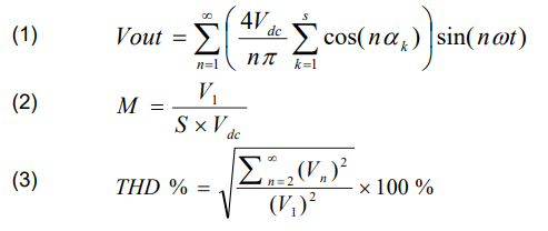
Where: M: – modulation index; V1: – fundamental voltage; S : – number of dc source ; αk: – switching angle; Vn: – output voltage for the nth harmonic. [22]
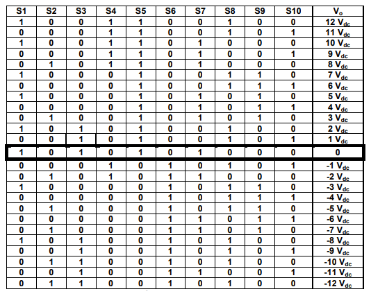
Fig.2. show a 25-level inverter circuit diagram proposed consisting of 12 power semiconductor switches and four dc sources where (Vdc2 = 5 × Vdc1)

Table. 1. Show the Switching states for the 25-levels inverter for all switches:-
Table. 1. Switching state for the 25 levels topology
Optimization Algorithms
In this research, we will address the use of multiple and various algorithms to calculate the switching angles and compare the algorithms used and combine their work to extract the optimum values of these angles to reduce harmonics contents to the least possible amount.
The most common optimization algorithms used are Genetic algorithms (GA). Slime moiled algorithm (SMA).[28]. Gary wolf algorithm (GWO). Whale optimization algorithm (WOA). Augmented Grey Wolf Optimizer and Cuckoo Search for Global Optimization (AGWO_CS). Artificial Bee Colony Optimization (ABC) Achieved to obtain the required optimum solution for calculating switching angles for MLIs for the wide range of Modulation index M%. [27-32]. Fig. 3. show the flowchart of optimizing proses for Genetic algorithm optimization.
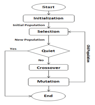
Fig. 4. Represents the calculations percentage error of objective function versus iterations of optimization algorithm, while Fig. 5. Show the variations of switching angles with modulation index


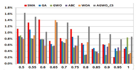
Fig. 6. Show the calculations error % versus changing modulation index (M) for all optimization algorithms used, and we note that (SMA) and (ABC) optimization algorithms have the lowest error at (M=0.95 and M=1) respectively.
Results of Simulation and Experiment
A 25-levels single-phase inverter with a PV array is The simulation was done in MATLAB/Simulink as shown in Fig. 7. The switching angles are chosen at M=1 and the frequency f=50Hz. The inverter drives the R-L load of R=20Ω, L=100mH. Vdc1=10V and Vdc2=50V.
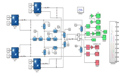
Fig. 8. Show the resulting THD from each algorithm used (SMA), (GA),(GWO),(ABC),(WOA), and (AGWO_CS) with Optimum THD from minimum points vs. modulation index 0.5 to 1 and

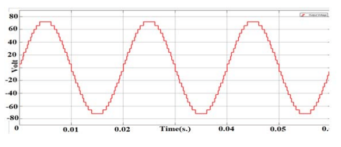
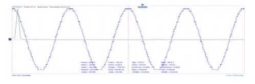
Figs. 9.a. and 9.b. display the 25-level inverter single-phase output voltage waveform and its FFT respectively at M=1.
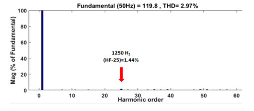
Figs. 10.a. and 10.b. show the waveform of Output current 25-level single-phase inverter and FFT analysis at Modulation Index = 1 and switching in degree angels is (θ1=1, θ2=6.8, θ3=12, θ4=14.9, θ5=22.4, θ6=27.7, θ7=31.15, θ8=39.13, θ9=42.96, θ10=50.33, θ11=58.66, θ12=70.44) and (R=20 Ω, L = 100 mH), the output voltage and current THD equal to 2.9%, 1% respectively and it’s clear that is less than 5% (IEEE standard)
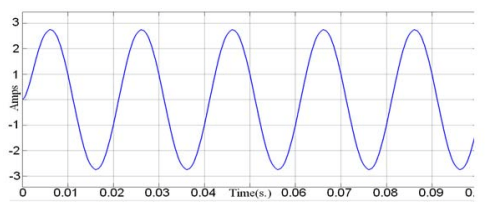

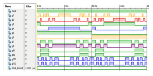
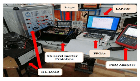
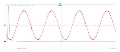
Fig. 11. Show the pulses pattern signals for each MOSFET in ISE Simulator of (VHDL) code for (FPGA) Kit. A prototype of a 25-level single-phase inverter with (FPGAs) (SPARTAN-3E) is employed as a gate driving circuit as shown in Figs. 12. to verify the simulation results, the (25- level) single-phase inverter practical circuit is gate driving with opt-isolators circuit type (TP250). It consists of Modified full-bridge twelve (MOSFETS) reduced switches inverters that are supplied form. Four PV Panels Also, the output frequency it’s assumed to be 50 Hz.
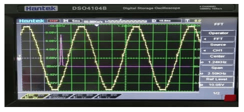
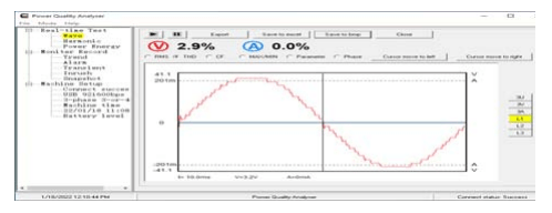
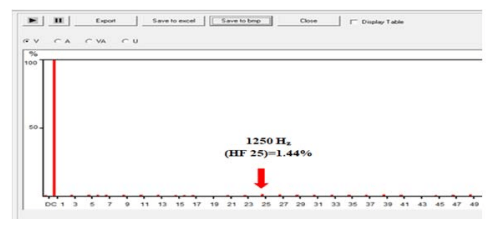
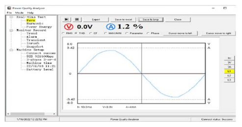
Figs. 13.a. and 13.b. shows the output waveform and by using a power analyzer the practical THD of the load voltage is equal to (2.9%) as shown in Fig. 13.c. while Fig. 13.d. shows the practical FFT of the load voltage. and Figs. .14. a., 14.b. and 14.c. show the waveform of output current and its FFT and THD = (1.2%) for (25-level) single-phase inverter at M=1 and the dc input voltage vdc1= 6V and vdc2=30V. The output inverter voltage spectrum shows the elimination of harmonics for inverter output voltage (from 3rd to 23rd) and the lowest order harmonic (LOH) is 25th (h25=1250Hz)..

Conclusion
For this paper, eliminating the (LOH) using optimum switching angles calculation, these angles are chosen throw solving multiple variables transcendental equations by using slime moiled algorithm (SMA), Artificial Bee Colony (ABC), Genetic algorithms (GA), Whale optimization algorithm (WOA), and grey wolf algorithm (GWO). The design strategy for a 25-level single phase inverter show the THD for load voltage and current equal to 2.9%, 1% respectively while the practical results show the load voltage and current THD is equal to 2.9%, 1% respectively, the Practical results were validated the simulation results of the proposed method.
REFERENCES
[1] Leon Freris, David Infield (2008),’’ Renewable Energy in Power Systems’’. WILEY, pp 240.
[2] Mohammed Shihab Ibne Tarek, Asad Siam, Muhammad Zia, Md. Mizanur Rahman (2018),” A Novel Five-Level Inverter Topology with Reactive Power Control for Grid-Connected PV System”. IEEE,pp101-105
[3] S. Kouro et al., “Recent Advances and Industrial Applications of Multilevel Converters,” in IEEE Transactions on Industrial Electronics, vol. 57, no. 8, pp. 2553-2580, Aug. 2010.
[4] J. Rodriguez, S. Bernet, B. Wu, J. O. Pontt and S. Kouro, “Multilevel Voltage-Source-Converter Topologies for Industrial Medium-Voltage Drives,” in IEEE Transactions on Industrial Electronics, vol. 54, no. 6, pp. 2930-2945, Dec. 2007.
[5] S. Du, B. Wu and N. Zargari, “Delta-Channel Modular Multilevel Converter for a Variable-Speed Motor Drive Application,” IEEE Transactions on Industrial Electronics, vol. 65, no. 8, pp. 6131-6139, Aug. 2018.
[6] C. M. N. Mukundan, K. Mithun and P. Jayaprakash, “Modular fivelevel inverter with binary sources based DVR for power quality improvement,” 2017 International Conference on Technological Advancements in Power and Energy (TAP Energy), Kollam, 2017, pp. 1-6
[7] A. Kavousi, B. Vahidi, R. Salehi, M. K. Bakhshizadeh, N. Farokhnia, and S. H. Fathi, “Application of the bee algorithm for selective harmonic elimination strategy in multilevel inverters,” IEEE Trans. Power Electron., vol. 27, no. 4, pp. 1689–1696, 2012, doi: 10.1109/TPEL.2011.2166124.
[8] M. A. Memon, S. Mekhilef, and M. Mubin, “Selective harmonic elimination in multilevel inverter using hybrid APSO algorithm,” IET Power Electron., vol. 11, no. 10, pp. 1673–1680, 2018, doi: 10.1049/iet-pel.2017.0486.
[9] S. D. Patil and S. G. Kadwane, “Hybrid optimization algorithm applied for selective harmonic elimination in multilevel inverter with reduced switch topology,” Microsyst. Technol., vol. 24, no. 8, pp. 3409–3415, 2018, doi: 10.1007/s00542-018-3720-x.
[10] L. Manai, F. Armi, and M. Besbes, “Performance comparison between optimization algorithms for asymmetrical cascaded multilevel inverter control,” Automatika, vol. 61, no. 4, pp. 626–642, 2020, doi: 10.1080/00051144.2020.1810505.
[11] I. A. Adeyemo, J. Ojo, and O. Adegbola, “Performance Evaluation of Three Evolutionary Algorithms for Selective Harmonic Elimination in Voltage Source Multilevel,” vol. 3, no. November, pp. 25–42, 2015.
[12] I. Journal and O. F. Scientificengineering, “Real Coded Genetic Algorithm Approach to Harmonic Reduction in Multilevel Inverters for Drives,” no. SEPTEMBER, 2015.
[13] Javid Mohtasham (2015),” Review Article-Renewable Energie”, ELSEVIER PP1289 – 1297.
[14] Jae-Sub Ko, Jun-Ho Huh, and Jong-Chan Kim (2020),’’ Overview of Maximum Power Point Tracking Methods for PV System in Micro Grid’’, Electronics, PP1-22.
[15] Bidyadhar Subudhi, Raseswari Pradhan, R (2012)’’ A comparative study on maximum power point tracking techniques for photovoltaic power systems’’. IEEE, 4, PP 89–98.
[16] Po-Cheng Chen, Po-Yen Chen, Yi-Hua Liu, Jing-Hsiao Chen, YiFeng Luo(2015), ‘’A comparative study on maximum power point tracking techniques for photovoltaic generation systems operating under fast-changing environments’’, ELSEVIER PP261–276.
[17] Omar Diouri, Najia Es-Sbai, Fatima Errahimi, Ahmed Gaga, and Chakib Alaoui (2019),’’ Modeling and Design of Single-Phase PV Inverter with MPPT Algorithm Applied to the Boost Converter Using Back-Stepping Control in Standalone Mode’’, International Journal of Photoenergy, PP1-16
[18] Takuro Sato, Daniel M. Kammen, Bin Duan, Martin Macuha, Zhenyu Zhou, Jun Wu, Muhammad Tariq, Solomon Abebe Asfaw (2015), ‘’SMART GRID STANDARDS SPECIFICATIONS, REQUIREMENTS, AND TECHNOLOGIES’’, WILEY, PP43.
[19] Ahmed M. T. Ibraheem AL-Naib,( 2016) ,”Modeling and Simulation of Solar Photovoltaic Array using MATLAB/Simulink”, AL-Taqani Journal, Vol. 29, No. 1, PP. 55-65.
[20] V. Jammala, S. Yellasiri and A. K. Panda, “Development of a New Hybrid Multilevel Inverter Using Modified Carrier SPWM Switching Strategy,” in IEEE Transactions on Power Electronics, vol. 33, no. 10, pp. 8192-8197, Oct. 2018.
[21] S. Foti et al., “An Optimal Current Control Strategy for Asymmetrical Hybrid Multilevel Inverters,” in IEEE Transactions on Industry Applications, vol. 54, no. 5, pp. 4425-4436, Sept.-Oct. 2018.
[22] M. H. Rashid, “Power electronics circuits, Devices and applications”, 3rd Edition 2004, Pearson prentice Hall, pp.862
[23] Rodríguez J, Lai J, Peng FZ. Multilevel inverters?: A survey of topologies. IEEE Trans Ind Electron Control Appl 2002;49(4):724–38
[24] Malinowski M, Gopakumar K, Rodriguez J, Perez MA. A survey on cascaded multilevel inverters. IEEE Trans Ind Electron 2010;57(7):2197–206.
[25] Wu B. High-power converters and AC drives. New York: Wiley IEEE; 2006
[26] M. D. Siddique, S. Mekhilef, N. M. Shah, A. Sarwar, A. Iqbal, and M. A. Memon, “A New Multilevel Inverter Topology with Reduce Switch Count,” IEEE Access, vol. 7, pp. 58584–58594, 2019, doi: 10.1109/ACCESS.2019.2914430.
[27] H. Someya and M. Yamamura, “A Genetic Algorithm for Function Optimization,” IEEJ Trans. Electron. Inf. Syst., vol. 122, no. 3, pp. 363–373, 2002, doi: 10.1541/ieejeiss1987.122.3_363.
[28] S. Li, H. Chen, M. Wang, A. A. Heidari, and S. Mirjalili, “Slime mould algorithm: A new method for stochastic optimization,” Futur. Gener. Comput. Syst., vol. 111, pp. 300–323, 2020, doi: 10.1016/j.future.2020.03.055.
[29] A. M. Lippert and R. D. Reitz, “Modeling of multicomponent fuels using continuous distributions with application to droplet evaporation and sprays,” SAE Tech. Pap., vol. 69, pp. 46–61, 1997, doi: 10.4271/972882.
[30] S. Mirjalili and A. Lewis, “The Whale Optimization Algorithm,” Adv. Eng. Softw., vol. 95, pp. 51–67, 2016, doi: 10.1016/j.advengsoft.2016.01.008.
[31] S. Sharma, R. Kapoor, and S. Dhiman, “A Novel Hybrid Metaheuristic Based on Augmented Grey Wolf Optimizer and Cuckoo Search for Global Optimization,” ICSCCC 2021 – Int. Conf. Secur. Cyber Comput. Commun., pp. 376–381, 2021, doi: 10.1109/ICSCCC51823.2021.9478142.
[32] K. Bhokray, “Artificial Bee Colony Optimization,” no. October, 2016, doi: 10.13140/RG.2.2.22854.06720.
Source & Publisher Item Identifier: PRZEGLĄD ELEKTROTECHNICZNY, ISSN 0033-2097, R. 98 NR 8/2022. doi:10.15199/48.2022.08.3
