Published by Maciej CIUBA1, Michał WOJCIECHOWSKI1, Maciej OWSIŃSKI2, Michał BORECKI1,
Warsaw University of Technology, Koszykowa 75, 00-662 Warszawa, Poland (1)
Institute of Power Engineering – Research Institute, Mory 8, 01-330 Warszawa, Poland (2)
Abstract. The presented article discusses the differences in the results of the electric field simulation in a medium voltage heat-shrinkable cable termination with the most probable assembly faults. Two types of voltage excitation were set as the boundary condition for a model of a real object. The first was a typical electrostatic excitation, and the second was the AC voltage with mains frequency. Both were used for cable accessories with selected assembly omissions. Consideration of the effect of the excitation type suggests that for cable accessories, field simulation using only electrostatics leads to unreal results and incorrect inference about the location of zones with the highest electrical stresses.
Streszczenie. Prezentowany artykuł omawia wpływ zadanego wymuszenia na różnice w wynikach symulacji pola elektrycznego w termokurczliwej głowicy kablowej średniego napięcia z najbardziej prawdopodobnymi błędami montażu. Przyjęto dwa rodzaje wymuszenia napięciowego jako warunek brzegowy w modelu bazującym na konstrukcji rzeczywistej głowicy. Pierwszym było typowe wymuszenie elektrostatyczne, a drugiem wymuszenie napięcia przemiennego. Oba zostały zastosowane dla osprzętu kablowego z wybranymi błędami montażu. Uwzględnienie wpływu typu wymuszenia sugeruje, że w przypadku osprzętu kablowego symulacja pola z zastosowaniem wyłącznie elektrostatyki prowadzi do nierzeczywistych wyników oraz błędnego wnioskowania co do lokalizacji stref o największych naprężeniach elektrycznych. Wybór rodzaju wymuszenia a wyniki symulacji pola elektrycznego w głowicy kablowej SN
Keywords: Cable termination, numerical simulation, electric field distribution, assembly fault
Słowa kluczowe: głowica kablowa, symulacja numeryczna, rozkład pola elektrycznego, błąd montażu
I. Introduction
The need to use cable accessories causes discontinuity of cable insulation and which in turn causes a nonuniformity of electric field distribution. Damages of cable accessories are one of the main reasons for the failure of cable power systems in general [1]-[3] even with sophisticated types of protecting devices [11, 12]. Possible sources of local increase of electric field strength may include assembly faults during the preparation of cable termination like gaseous cavities, contaminants on the insulation surface, the omission of assembling of the stress control element or just incorrect cable accessory choice. Further parts of this paper describe the results of two possible ways to simulate electric field distribution of heat shrink cable termination which is based on its common use.
II. Compared Computing Methods
Electrostatic Analysis
The dependent variable for this analysis is the electric potential. Considered electrostatic analysis based on two Maxwell equations for linear media

where (1) is Gauss’s law with D – electric flux density and ρ – charge density, (2) is Faraday’s law with E – electric field strength
Conductivity does not occur in formulas mentioned above so all materials between conductors were considered as perfect insulators (σ = 0 (S⋅m-1)). Therefore electric field distribution depends only on the permittivity of materials and possible occurrence of uncompensated electric charges.
AC Analysis
This type of analysis also uses electric potential as a dependent variable to estimate electric field strength (3) implemented in the time-harmonic equation of continuity (4).

with: V – electric potential, E – electric field strength, J – current density, D – electric flux density, Je – external current density, σ – conductivity, ω – angular frequency and j – imaginary unit. Equations (3) and (4) describe electric field in lossy materials where both permittivity and resistivity affect the distribution of electric field between conductors. Both methods described above were implemented to simulations of two different cases:
• cable termination correctly assembled according to the installation instructions;
• the omission of assembly semiconducting mastic;
• assembly of semiconducting mastic and stress control tube has been ignored.
III. Model preparation
The created model was based on real heat-shrinkable termination (Fig.1 and Fig.2). The terminated cable is XRUHAKXS 120/50RMC 12/20 kV type of XLPE extruded MV cable [4].
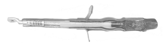

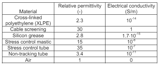
The cross-section of a real object allowed measuring the dimensions of each part of the accessory. Dimensions were measured with a caliper of 0.02 mm precision. Materials properties mentioned in [5]-[9] were used in the considered model.
Table I. Values of material properties used in model
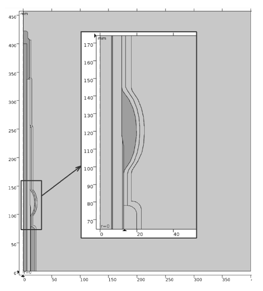
Different cases of modeled cable termination were computed with the use of the AC/DC Module in the Comsol Multiphysics environment. Figure 3. shows a general view of the axisymmetric model of correctly assembled heatshrinkable MV cable termination and magnified part with a cutting point of cable screening covered by stress control mass.
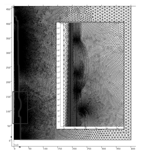
To fulfill the requirements of the FEM algorithm some boundary conditions should be applied. In both, electrostatic and AC analysis, Dirichlet boundary conditions were chosen, which means selected conductors surfaces obtain electric potentials. The next step for any solved problem is to build the mesh. Discretization (Fig.4.) of examined areas was made by automatic built-in algorithm with manually slightly changed parameters like the ratio between the size of two adjacent grid elements to dense mesh in important areas with expected electric field intensification.
To solve partial differential equations MUMPS (MUltifrontal Massively Parallel Sparse direct Solver) direct solver was used.
IV. Results of simulation
Correctly assembled cable termination
This section aims to investigate the electric field distribution of clean and properly assembled termination and compare results of simulation on the same model but under two different physics mentioned in section II.

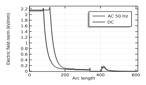
The first results of electric field simulation for both possibilities show (Fig.5) substantial difference in its distribution. Area of discontinuity of uniformity of electric field has moved from cable screen ending closer to cable semiconducting screen layer ends. Graph (Fig.6) present electric field strength for both possible simulation types along the straight line in cable termination at radius r = 11 (mm), where the green line is for electrostatic analysis and the blue one is for AC analysis.

Cable termination without semiconducting mastic
This section consist investigation of electric field distribution of termination assembled with omission of semiconducting mastic and compare results of “electrostatics” and “electric current” simulation on the same model (section II).

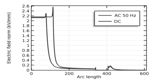
As in the first case also two quantities distribution was considered: potential distribution (Fig.7) on the surface of the cross-sectional area of termination and part of its surrounding, and electric field strength (Fig.8) longwise line on radius r = 11(mm) from the axis of a 2d-axisymmetric model of cable termination.
Cable termination without semiconducting mastic and stress control tube
This section aims to investigate the electric field distribution of improperly assembled termination and compare results of simulation on the same model but under two different types of physics (section II).
Moreover, maximal electric field potential value from AC simulation as before is higher than in electrostatic solution.
Once more electric field distribution significantly changes (Fig. 9) only because of use different type of simulation conditions. Both analyzed quantities: potential (Fig.5, 9) and electric field strength (Fig. 6, 10) show that difference.

V. Conclusions
That means the results of modeling could affect the design of a final product and its reliability and also position on the market. As it has been shown in the previous part of the article, incorrect choice of physics type could easily lead to erroneous conclusions. The possibility of an incorrect assembly of cable accessory constrain the designer to change the project and also the production process, therefore, it is very important to carefully build a numerical model with the correct parameters and correctly chosen physics. The best way to obtain it is to set model parameters possibly closest to the designed work conditions of the real object.
In the case of cable termination, it is very risky to simulate it with the electrostatic field. Regardless of modeled mistakes in the assembly process, this study shows that for electrostatics the most electrically stressed area appears always at the end of the deflected cable screen.
The omission of semiconducting termination parts assembly lead to an increase of potential gradients close to cable screen end.
REFERENCES
[1] Gulski, “Knowledge rules for partial discharge diagnosis in service”, Cigre TF 15.11/33.03.02, 2002, pp. 1-88.
[2] K.P. Meena, B.N. Rao, T. Thirumurthy, G.K. Raja, “Failure analysis of medium voltage cable accessories during qualification tests”, 10th IEEE Int. Conf. Properties and Applications of Dielectric Materials, Bangalore, India, 2012, pp. 1-4
[3] G. Mazzanti; M. Marzinotto, “Combination of probabilistic electro-thermal life model and discrete enlargement law for power cable accessories”, 2016 IEEE International Conference on Dielectrics (ICD), vol.2, 2016, pp.780-783
[4] NKT Cables, XRUHAKXS 12/20 kV Data Sheet, 2016
[5] Aarnio, Anssi, “Characterization of non-metallic materials for medium voltage, cable accessories”, Master’s thesis, Tampere University of Technology, Material Science, 2010
[6] “SCO Silicone Grease Compound”, Electrolube company catalogue, Revision: 3 April 2016
[7] Illias, H. A.; Lee, Z. H.; Bakar, A. H. A. & Mokhlis, H. 2012. Distribution of electric field in medium voltage cable joint geometry. 2012 IEEE International Conference on Condition Monitoring and Diagnosis 23–27 September 2012, Bali, Indonesia.
[8] Olli Kuusisto, “The Effects of Installation-Based Defects in Medium Voltage Cable Joints”, Bachelor thesis, Helsinki Metropolia University of Applied Sciences, Electrical Power Engineering, 2016
[9] I.A. Metwally, A.H. Al-Badi, A.S. Al-Hinai, F. Al Kamali and H. Al-Ghaithi, “Influence of Design Parameters and Defects on Electric Field Distributions inside MV Cable Joints”, IEEE 2016, Proceedings of the 18th Mediterranean Electrotechnical Conference (MELECON)
[10] Ciuba M., Owsiński M., Sul P.: Analiza rozkładu pola elektrycznego w termokurczliwej głowicy kablowej z wadą montażu, in: Elektronika – konstrukcje, technologie, zastosowania, vol. 1, no. 11/2016, 2016, pp. 64-66, DOI:10.15199/13.2016.11.13
[11] M. Borecki, J. Starzyński, Z. Krawczyk, “The comparative analysis of selected overvoltage protection measures for medium voltage overhead lines with covered conductors”, Conference on Progress in Applied Electrical Engineering, ISSN 978-1-5386-1528-7, pp. 1-4, 2017, DOI: 10.1109/PAEE.2017.8009014
[12] M. Borecki, S. Wincenciak, “Simulation of Electric Field on the Surface of a Long Flashover Arrester”, 17th International Conference on Computational Problems of Electrical Engineering (CPEE 2016), ISSN 978-1-5090-2800-9, pp. 1-4, 2016, DOI: 10.1109/CPEE.2016.7738763
Authors: Maciej Ciuba1, Michał Wojciechowski1 , Maciej Owsiński2 , Michał Borecki1, Warsaw University of Technology (1), Koszykowa 75, 00-662 Warszawa, Poland e-mail: maciej.ciuba@ee.pw.edu.pl, michal.wojciechowski@ee.pw.edu.pl Institute of Power Engineering – Research Institute (2), Mory 8, 01- 330 Warszawa, Poland e-mail: maciej.owsinski@ien.com.pl
Source & Publisher Item Identifier: PRZEGLĄD ELEKTROTECHNICZNY, ISSN 0033-2097, R. 96 NR 4/2020. doi:10.15199/48.2020.04.25
