Published by Józef PASKA, Karol PAWLAK, Pola RONKIEWICZ, Paweł TERLIKOWSKI and Jan WOJCIECHOWSKI*Warsaw University of Technology, Institute of Electrical Power Engineering, Poland
Abstract: This paper presents the analysis of Polish rivers’ potential to be employed in the construction of new electricity sources. On the basis of the hydrological data obtained in a number of years, set of parameters for 28 water gauges were assessed. The water gauges chosen were meant to display characteristics representative for the whole country. The analysis was preceded by general information concerning the Polish hydropower sector. Finally, the case study of small hydroelectric power plant (SHP) was presented. The location of the planned power plant is the northern part of Poland, in Suraż near the water gauge on the Narew River.
Streszczenie: W artykule przedstawiono analizę potencjału polskich rzek do wykorzystania w budowie nowych źródeł energii elektrycznej. Na podstawie danych hydrologicznych uzyskanych w ciągu kilku lat oceniono zestaw parametrów dla 28 wodowskazów. Wybrane punkty wodowskazowe miały zobrazować cechy charakterystyczne dla całego kraju. Analiza została poprzedzona ogólnymi informacjami dotyczącymi polskiego sektora energetyki wodnej. Na koniec przedstawiono studium przypadku małej elektrowni wodnej (MEW). Lokalizacja planowanej elektrowni to północna część Polski, w Surażu koło wodowskazu na Narwi. (Zasoby hydroenergetyczne Polski i przykład ich wykorzystania).
Keywords: hydropower industry in Poland, small hydropower plants (SHP), Polish rivers hydropower potential, example of SHP.
Słowa kluczowe: hydroenergetyka w Polsce, małe elektrownie wodne, potencjał energetyczny polskich rzek, przykład MEW.
Introduction
According to the 2030 EU climate and energy framework, the share of renewable energy sources should amount to at least 27% of EU energy consumption [1]. Energy production with the use of hydropower plants is widespread globally, accounting for one fifth of the total global power generation [2].
Poland, a medium-size country in central Europe, has the entire panoply of possibilities to further develop and expand effective sources of electrical energy, which use the power of water flow to produce energy. Due to Poland’s geographical localization, vast majority of watercourses streaming through the country have their river head and river mouth inside the Polish territory. Therefore, the process of development of hydropower sector rests with Polish politicians forming energy policies.
In 2017, hydroelectric power plants in Poland reached a total capacity of 2.376 GW, which is 5.5% of the capacity installed in the Polish energy sector and produced 2767 GWh of electricity, covering 1.7% of the country’s demand [3]. In addition to the larger hydroelectric power plants, there are also over 700 small hydropower plants [4] that are officially classified as renewable energy sources, not hydroelectric power sources, hence their power is not added to hydropower reports. To be called a small hydropower plant in Poland, the source installed capacity must be under 5 MW. In 2017, all small hydropower plants achieved a total capacity of 0.988 GW [5].
The main condition that the river must meet in order to be used in the energy production process is the flow rate higher than the minimum allowable flow, defined as the minimum flow rate to be maintained in a watercourse perpendicular to the structure to maintain biological balance and water consumption downstream [6]. In Poland, this parameter for most rivers is defined and published by the Institute of Meteorology and Water Management (IMGW). If the watercourse chosen for the construction of the energy source is not included in the IMGW publication, the minimum allowable flow should be calculated using the following formula:

where: Qn – minimum acceptable flow [m3/s], K – correction factor [-], SNQ – average low flow [m3/s]. In such a case, the value of K factor fluctuates between 0.5 and 1.5, and depends on hydrological type of watercourse.
The smallest of small hydropower plants, called micro installations or micro hydropower plants, need flow values even as low as 1 m3/s. Bearing such a possibility in mind, an analysis was carried out to assess the potential of the Polish hydropower resources, putting emphasis on small hydropower plants utilization.
Water gauge data
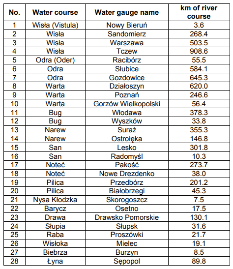
To perform the analysis, 28 water gauges in Poland were chosen (Table 1 and Figure 1). The selection of these places was based on the following criteria:
• the size of rivers in the country, with the attention given to the most significant ones;
• places exposed to risk of flood;
• water courses representative when it comes to regional or national hydrological conditions.
On the basis of the average monthly flows of the rivers analyzed, average annual value was calculated for each of three flows. Results were presented in Table 2. SWQ means average high flow and SSQ – average of medium flow.
Accurate choice of components for small hydropower plant, particularly water turbine and generator, demands a broad knowledge of not only water flows, but also flow duration curves. These data show how many days a year a certain value is achieved in the analyzed water gauges.
Annual flow-duration data for 28 chosen water gauges were presented in Tab. 3. They refer to lower flows, lasting for over 300 days per year, and should be understood in the following manner: water gauge no. 1, duration of 310 days – during 85% of the year the water flow will be 7.10 m3/s or higher.
Table 1. The list of water gauges selected to carry out the analysis

Data analysis
As it can be seen in Table 2, even the average low flows (SNQ) are in vast majority much higher than the minimal value of 1 m3/s. It means that using water flow as energy source in Poland is highly reasonable, even if only micro installations are considered.
Table 2. Average annual water flows for selected water gauges [7]

Table 3. Annual flow-duration data for selected water gauges

Hydropower plants, especially with storage reservoir, even a small one, are not only sources of electrical energy, but also water flow regulators. On the one hand, they can protect nearby area against water overflow during floods and, on the other hand, retain water to avert drought. On the basis of the average annual water flows, mean percentage differences between chosen water flows (SWQ – SSQ and SSQ – SNQ) were calculated. Taking the data obtained in this way into consideration, one may appoint the location of gauge stations on the basis of the highest flow differences and the location most likely to be hit by floods.
As it can be observed, upland rivers are characterized by significant differences between SWQ, SSQ and SNQ flows – over 200% to nearly 400%. It can mean that average of medium flow could be even four times higher than average low flow. A river bed could not contain as big high-water stage as the mentioned one, what leads to local or regional flooding. Lowland and coastal parts of water courses are marked by lower flows differences, usually below 180%.
In order to assess power that a hydropower plant can generate, mathematical methods should be used. The first step is Bernoulli’s equation (2), presented below:

where: ρ – the density of the fluid (water) [kg/m3], υ– the fluid flow speed at a point on a streamline, [m/s], g – acceleration due to gravity (constant, 9.81 m/s2), h – the elevation of the point above a reference plane (e.g. surface of the Sea) [m], p – fluid pressure at the chosen point [kg/m2].
In such a case, the point of interest is the analysis for those parameters before and behind the plant, which may be rendered as:
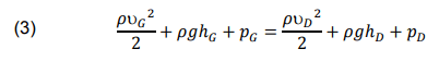
A formula (3) on the left demonstrates Bernoulli’s equation for water before the plant (subscript G), and on the right – water behind the plant (subscript D). Importantly, hydropower is in practice a combination of potential energy (Ep), possessed by water due to its altitude, and kinetic energy (Ek), possessed due to its motion. Treating this as a basis, one must take into consideration two more physical laws that, together with Bernoulli’s equation, help to create a formula for hydropower plant power.

where: m – mass is a product of density and volume of an object.
Energy used by the hydropower plant is a difference between a hydropower before and the one behind the plant, which is reflected by the following formula:
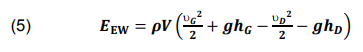
Fluid flow speeds before and behind the plant are usually equal [10], so the parts of the equation denoting kinetic energy, may be also reduced. Factoring out g and assuming that the difference between water before and behind the plant is its head H, mentioned above, leads to the following formula:

The result of the formula obtained is energy, therefore equation (6) should be eventually divided by time t, in order to achieve the result in the form of power P. Bearing in mind that flow Q described in the beginning of this paper is a quotient of volume and time, one may formulate the final equation for raw power (capacity) of a hydropower plant P. Substituting constant values ρ) for water 1000 kg/m3) and g a formula ready to be employed during calculations is as follows:

Raw power is a kind of power in case of which losses in turbines, generators and other parts of a plant are not considered, thus its value multiplied by efficiency equals the real power (capacity) of a source. As it is presented in Tab. 3, for the majority of analyzed gauge stations the flow with 310 days flow-duration amounts to over 10 m3/s. Such a water flow value, with a head of 2m and efficiency of the plant of 0.85, is enough to analyze it as an energy source for a plant generating power 167 kW, which could become the power supply for about 15–18 households. There is no reason not to build such sources close to one another, which may lead to generating even a number of megawatts from sources located along a short river section, as short as a few kilometers. While undoubtedly not every river on its whole distance is fit for the purpose of being used for hydropower plant construction, the existing possibilities are worth reflecting upon.
Case study
In order to properly present the potential of hydrological energy, a conceptual design of a small hydroelectric plant (SHP) was prepared on the basis of the analyses carried out. The location of the planned power plant is the northern part of Poland, in Suraż near the water gauge on the Narew River. Fig. 2 shows the location of the water gauge (in the black ellipse), at which a small hydropower plant will be designed. This point, similarly to the map in Fig. 1, is marked with the number 13.

This place was chosen because of:
• geographical location, where there are few power plants;
• flood risk on this section of the Narew river, which thanks to the investment will be reduced;
• small average flow and width of the river bed, allowing the use of a hydroelectric power plant on a small watercourse;
• uncertain energy security of the region, caused by the rare occurrence of transmission power infrastructure;
• the availability of land for investment, due to the location outside areas of heavily urbanized or limited environmental restrictions
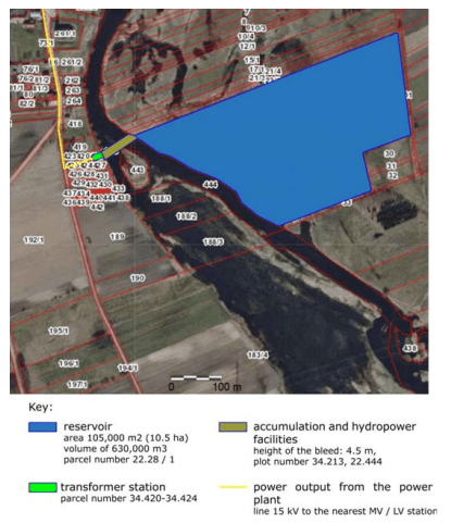
The area designated for the investment are plots in Suraż with the following numbers: 34.213 and 22.444 (dam and water part of the power plant), 22.28/1 (retention reservoir), 34.420-424 (electric part of the power plant)
In order to select the type and parameters of the water turbine, the data concerning the measuring point in Suraż was analyzed. Tables 4 and 5, and Fig.3 present monthly characteristic flows and average tides of a given duration and with higher ones.
Due to the very high probability of turbine utilization at nominal conditions for at least 70% of days in the year and the data contained in the tables listed above, a turbine with an esophagus of 6-7 m3/s will be used.
The minimization of the flood hazard will be implemented by an artificial retention reservoir with a volume of 630,000 m3, located before the damming up of the power plant in uncultivated land, currently unused. This reservoir, filled during floods of the river, will also be a water storage for a period of low water levels. In addition, it will have a recreational function for the residents of Suraż and the surrounding area, as the area of 10.5 ha allows the use of a reservoir for sailing, leisure, fishing and agro tourism purposes.
Table 4. Monthly characteristic flows for Narew in Suraż [m3/s]

Table 5. Average Q flows of given duration together with higher ones for Narew in Suraż


The damming up, thanks to which it is possible to more efficiently use the energy of flowing water, was designed to achieve a slope of 4.5 m. The height obtained is of rather low value due to the lowland terrain.
On the basis of the above data, the Kaplan turbine – TK30 HAb 1300-290 was matched, which is operating in a horizontal position, and supplying a 362 kW asynchronous generator, all manufactured by HPP. The generator, thanks to the use of permanent magnets, does not require energy consumption from the grid, for magnetizing the rotor. Tab. 6 depicts the dependence of turbine efficiency and power on flow.
In order to optimize the plant’s operation, a frequency converter was selected. A ACS880-77LC-860A / 800A-7 converter was selected for the needs of a small hydropower plant, converter belong to the ACS880 family of devices manufactured by ABB. The inverter is the smallest of fifteen devices in the series and can work with power sources with a total value of up to 800 kW. In the case of the Suraż power plant, the drive will use its capabilities in about 45%. In Table 7 information on electrical parameters of the ACS880-77LC-860A / 800A-7 converter was presented.
Table 6. Dependence of turbine efficiency and power on flow
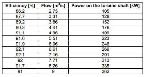
Table 7. Electrical data of the selected frequency converter

In order to include the designed energy source in the power grid, it is necessary to choose the right transformer. The power generated in the power plant will amount to 300- 370 kW, therefore for its derivation to electric power system (EPS) a medium voltage line of 15 kV will be used and this must also be the voltage of the transformer upper side. The lower side voltage is 525-690 V, which results from the output voltage of the drive. In this case, a transformer with a non-standard 0.6 kV / 15 kV transformation must be made. Assuming a generation at the rated level (362 kW) with an optimal transformer load of 80%, its power must be about 500 kVA. The calculation of this value is shown by the equation (8).
where: ST– apparent power of the transformer, Sgen – apparent power of the generator, Pgen – active power of the generator, cosφ – generator power factor.
The auxiliaries switchgear of the power plant will operate at a low voltage of 400 V. The transformer will be used for auxiliaries, with a 0.6 kV / 0.4 kV transformation. Accumulator battery will be the emergency power supply for auxiliaries’ switchgear of the power plant. Due to the conceptual stage of the project and the lack of information on the auxiliaries’ switchgear of the power plant, the devices have not been physically selected.
The generation of power in an asynchronous machine requires compensation of the inductive reactive power, therefore a battery of capacitors will also be used. A 29 kvar battery was chosen, which is justified by the calculation (9) and (10).

where: QC – capacitor bank power, tgφgen– generator’s reactive power factor, tgφEPS – EPS reactive power factor of 0.4.
Power output from the power plant, as mentioned above, will take place at 15 kV, from the nearest MV / LV station, located at a maximum of 700 m from the power plant site. 15 kV line will be routed to the energy measurement point of the designed source. The final course of the line has been included in the plan in Fig. 4. The electric scheme of the power plant, with all devices, is shown in Fig. 5.

Conclusions
All things considered, the Polish water courses show various hydropower potential. The conditions to build big many-megawatts’ hydropower plants are, admittedly, limited in Poland, but the analysis presented proves that investing in small hydropower plants installations is worth considering. The economic potential of Polish hydropower resources amounts to 24% [4], thus remaining 76%, which equals 6500 GWh per year, can be developed in the future. Due to hydropower plants efficiency even higher than 90% [9], hydropower energy sources may become more and more popular in the future, especially with the Polish law on wind power plant rendered stricter recently.
The potential of small hydropower plants (up to 10 MW) in Eastern Europe is used in approximately 43%, which amounts to 1.923 GW of installed capacity [11]. Due to global economic crisis at the beginning of the decade, rising costs of supporting RES growth, and frequent critics from the Climate Package, government economic incentives have been substantially limited during last years (e.g. Poland).Taking into consideration the above mentioned hydropower potential indicators, one may conclude that the development of small hydropower plants is definitely possible in Poland.
REFERENCES
[1] Proposal for a directive of the European Parliament and of the Council on the promotion of the use of energy from renewable sources (recast), 2016/0382, Brussels 2017
[2] Corley A.-M.: The future of hydropower, IEEE Spectrum, 2010, http://www.ieee.org
[3] Raport roczny z funkcjonowania KSE. Raport za rok 2017, PSE, http://www.pse.pl
[4] Paska J.: Rozproszone źródła energii, OWPW, Warszawa 2017
[5] Potencjał krajowy OZE. Moc zainstalowana. Stan na 31.03.2018, URE, http://www.ure.gov.pl
[6] Minimum acceptable flow measurement, Ultraflux, http://www.ultraflux.net
[7] Fal B. et al.: Przepływy charakterystyczne głównych rzek polskich w latach 1951-1990, IMGW, Warszawa 1997
[8] Mapa zagrożenia powodziowego, ISOK, http://www.mapy.isok.gov.pl/imap/
[9] Jarry-Bolduc D., Côté E.: Hydro energy generation and instrumentation & measurement: Hydropower plant efficiency testing, 2014, http://www.leonardo-energy.pl
[10] Karolewski B., Ligocki P.: Wyznaczanie parametrów małej elektrowni wodnej, Prace Naukowe Instytutu Maszyn, Napędów i Pomiarów Elektrycznych Politechniki Wrocławskiej nr 56, Wroclaw 2004
[11] Liu H., Masera D., Esser L.: World Small Hydropower Development Report 2016 Eastern Europe, UNIDO & ICSHP, 2016, http://www.smallhydroworld.org
Authors: prof. dr hab. inż. Józef Paska, Politechnika Warszawska, Instytut Elektroenergetyki, Zakład Elektrowni i Gospodarki Elektroenergetycznej, ul. Koszykowa 75, 00-662 Warszawa,
E-mail: jozef.paska@ien.pw.edu.pl; dr inż. Karol Pawlak, Politechnika Warszawska, Instytut Elektroenergetyki, Zakład Elektrowni i Gospodarki Elektroenergetycznej, ul. Koszykowa 75, 00-662 Warszawa,
E-mail: karol.pawlak@ien.pw.edu.pl; mgr inż. Paweł Terlikowski, Politechnika Warszawska, Instytut Elektroenergetyki, Zakład Elektrowni i Gospodarki Elektroenergetycznej, ul. Koszykowa 75, 00-662 Warszawa,
E-mail: Pawel.Terlikowski@pw.edu.pl; mgr inż. Pola Ronkiewicz, Politechnika Warszawska. Instytut Elektroenergetyki, Zakład Elektrowni i Gospodarki Elektroenergetycznej ul. Koszykowa 75, 00-662 Warszawa, E-mail: pola.ronkiewicz@ien.pw.edu.pl; mgr inż. Jan Wojciechowski, wojan18@gmail.com
Source & Publisher Item Identifier: PRZEGLĄD ELEKTROTECHNICZNY, ISSN 0033-2097, R. 96 NR 1/2020. doi:10.15199/48.2020.01.01
