Published by Filip RATKOWSKI1,2, Michał KOŁTUN2, Stanislaw CZAPP1, Gdańsk University of Technology (1), Eltel Networks Energetyka SA (2). ORCID: 1. 0000-0002-4698-9729, 3. 0000-0002-1341-8276
Abstract. The ampacity of power cables depends, among others, on the conditions of heat dissipation from the cable to the environment. Cables are usually laid directly in the ground, but in some sections, they may be placed in ducts, which adversely affects the ampacity of the cable line. The paper presents heat transfer phenomena for cables installed in pipe-type ducts filled with air. The effect of cable duct diameter on this ampacity is discussed. The results of the theoretical analysis have been validated by calculations performed with CYMCAP software. The comparison of the ampacity for air-filled vs. water- or bentonite-filled ducts is also included. The analyses and comparisons have shown that with an appropriate dimension of the duct, the simplest filling (with air) allows to obtain the ampacity not lower than when water or bentonite is used.
Streszczenie. Obciążalność prądowa długotrwała kabli elektroenergetycznych zależy między innymi od warunków oddawania ciepła z kabli do otoczenia. Kable są zwykle układane bezpośrednio w ziemi, ale na pewnych odcinkach stosuje się przepusty kablowe, co niekorzystnie wpływa na obciążalność linii kablowej. W artykule przedstawiono zjawiska wymiany ciepła w rurowych przepustach kablowych wypełnionych powietrzem. Przeanalizowano wypływ średnicy przepustów na tę obciążalność. Wyniki analizy teoretycznej zweryfikowano przy użyciu programu komputerowego CYMCAP. Porównano również obciążalność prądową długotrwałą kabli w przepustach wypełnionych powietrzem z obciążalnością w przypadku wypełnienia przepustów wodą lub bentonitem. Analizy i porównania wykazały, że przy odpowiednich wymiarach przepustu najprostsze wypełnienie (powietrzem) pozwala uzyskać obciążalność kabli w przepustach nie mniejszą niż przy zastosowaniu wody lub bentonitu. (Wpływ średnicy przepustów kablowych na obciążalność prądową długotrwałą kabli elektroenergetycznych wysokiego napięcia).
Keywords: high-voltage power cables, ampacity, cable ducts
Słowa kluczowe: kable wysokich napięć, obciążalność prądowa długotrwała, przepusty kablow
Introduction
In practice, the best possible heat dissipation from cables is needed to ensure their maximum ampacity. The solution for calculating the ampacity of underground power cables proposed by Neher-McGrath [1] has been widely accepted for over 60 years now. Today, the power industry uses IEC 60287-1-1 standard [2], where the Neher-McGrath model contributes a lot.
Generally, the ampacity of a power cable can be calculated from the following dependency [2]:

where (based on [2]) : IA – ampacity of the power cable, A; Δθ – permissible temperature rise of the conductor above the ambient temperature, K; Wd – dielectric loss per unit length per phase, W/m; T1 – thermal resistance (per core) between the conductor and sheath, (K.m)/W; T2 – thermal resistance between the sheath and armour, (K.m)/W; T3 – thermal resistance of external serving of the cable, (K.m)/W; T4 – thermal resistance between the cable surface and the surrounding medium (e.g. soil), (K.m)/W; nc – number of conductors in the cable; R – AC current resistance of the conductor at its maximum operating temperature, Ω/m; λ1 – ratio of total loss in metallic sheaths to total conductor loss; λ2 – ratio of total loss in metallic armour to total conductor loss, -.
When the cable line is laid in different ambient conditions, its permissible load depends on the section having the worst ability for heat dissipation. This mainly includes crossings with heat sources such as other power cable lines, heat and steam pipelines, or cables’ sections where laying conditions significantly change (e.g. cables partially laid in pipes/ducts or in free air with possible high insolation) [3–10].
To lay power cables in a significant depth, for long distances, and/or below various obstacles, the method called Horizontal Directional Drilling (HDD) is used (Fig. 1). The HDD is a method of installing an underground pipe/duct with trenchless technology, which involves the use of a directional drilling machine and associated attachments to perform drilling according to the assumed path. When a pipe is installed in the ground, the power cable is pulled inside the pipe. The cables laid in pipes are usually in trefoil formation and a separate pipe should be used for each single-conductor cable.
When the cable is installed in a deep pipe/duct, its ampacity significantly decreases, compared to the directly buried cables, which negatively influences both technical and economic aspects. The key factors affecting the ampacity for this kind of installation are: dissipation of the heat coming from a long distance to the ground surface, thermal resistivity of the pipe/duct filling (bentonite, water, or just air), as well as in the case of bentonite utilization, the effects of possible formation of voids inside the duct resulting from bentonite fluid injection imperfections during the processes of directional drilling [11] and drying-out of the bentonite.

Fig. 2 presents the results of an experiment examining the bentonite drying-out phenomenon inside the bucket. After taking the original liquid form (during preparation) needed to pour it into a duct, the bentonite changes the characteristics to those of a gel medium – it shrinks and cracks, because of drying-out. According to [12], the thermal resistivity of bentonite is usually below 1.0 (K.m)/W, in both fluid and solid form – and this value (1.0 (K.m)/W) is recommended as the reference for the native soil in various countries while designing cable lines [13, 14]. However, the drying-out process makes that some parts of bentonite filling become behaving as air-filled areas, which negatively influences the originally assumed heat transfer.
Another filling medium in pipes/ducts is water. It is easy to use and has low thermal resistivity (25 times lower than air [8]). The disadvantages of using water as filling medium include the tendency to evaporation and the necessity of refilling when the pipes are unsealed. Moreover, water tends to make a microbiological film on the cable and the internal surface of the pipe, which worsens the heat dissipation.

As the CIGRE document reports [15], warmer water tends to collect at higher points of the duct, thus causing a difference of about 10 °C between the temperatures along the length of the pipe/duct. The phenomenon of different temperatures along the water-filled duct was also observed in Distributed Temperature Sensing (DTS) measurements of Stadium – “Powiśle” substations for the 110 kV power cable line in Warsaw, Poland [16]. The maximum temperature difference amounting to around 10 °C along the duct (Fig. 3) reduced the positive effect of water filling in some duct sections.

Taking in mind the aforementioned disadvantages of filling the ducts with water or bentonite, it is reasonable to focus on the optimization of dimensions of cable pipes/ducts filled with air. This type of duct filling is the simplest (compared to bentonite or water), and, as the authors’ further investigation will show, the air-filled duct may give the ampacity not worse than that provided by the water- or bentonite-filled duct.
The further part of the paper presents the investigation of the ampacity of power cables laid in pipe-type ducts. Heat transfer phenomena in such a cable arrangement are analyzed. The effect of pipe diameter on the ampacity of the power cable is presented.
Assumptions for the ampacity analysis
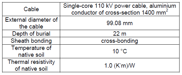
The analysis of the high-voltage power cable ampacity is conducted for the cable line formation depicted in Fig. 4 and ambient parameters colated in Table 1.
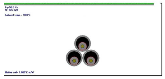
Table 1. Cable type and other parameters assumed in the analysis
If the power cable is laid in a duct, its external thermal resistance T4, included in (1), consists of three components [17]:

where: T4’ – thermal resistance of the air space between the cable surface and the duct internal surface, (K.m)/W, T4” – thermal resistance across the wall of the duct, (K.m)/W; T4“‘ – external thermal resistance of the duct, (K.m)/W.
The cable arrangement in the air-filled duct is shown in Fig. 5, along with relevant heat transfer components. The heat transfer consists of the following components:
1) convection from the cable surface to the air inside the duct,
2) convection from the air inside the duct to its wall,
3) longitudinal convection due to either forced or natural flow of air along the duct,
4) surface-to-surface radiation from the cable surface to the duct wall.
5) conduction across the duct wall.
The thermal resistance T4” mainly depends on the parameters of the material used to produce the duct and the external/internal diameter ratio. The thermal resistance T4“‘ mainly depends on the environment around the duct and the area of heat transfer from it. However, from the point of view of the effect of the duct on the cable ampacity, the most interesting term is the thermal resistance T4’. According to the dependency (3) derived from [17] it can be concluded that for air-filled pipes/ducts, the resultant thermal resistance of the air space between the cable surface and the pipe/duct internal surface does not depend on pipe diameter:

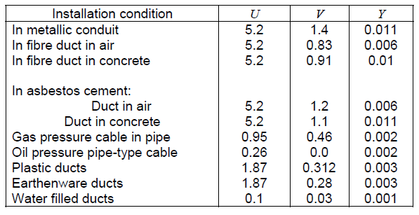
where: De – external diameter of the cable, mm; θm – mean temperature of the medium filling the space between the cable and duct, °C; U, V, Y – constants depending on the type of installation, given in Table 2.
Table 2. Values of constants U, V and Y used in (3), according to [17]
The above conclusion regarding the thermal resistance T4’ significantly simplifies the analysis of the ampacity of cables in ducts.
Analysis results
As aforementioned, the ampacity of power cables depends on the intensity of heat dissipation from cables to the surrounding space. For the purpose of the analysis, the total power loss (per unit length) generated in the cable is marked as Wt. Based on Fig. 5, this power loss is dissipated to the environment by convection, conduction and radiation:

where: Wconv,s – natural convection heat transfer rate between the cable external surface and the surrounding medium, per unit length, W/m; Wcond – conductive heat transfer rate in the medium surrounding the cable, per unit length, W/m; Wrad,s-w – thermal radiation heat transfer rate between the cable external surface and the duct (pipe) internal surface, per unit length, W/m.
To evaluate the ampacity of the cable placed in the air-filled duct as a function of duct diameter, an algorithm was created which analytically calculates power loss dissipation from the cable. The components included in (4) can be calculated from the following expressions [4]:

where: hs – natural convection coefficient at external surface of the cable, W/(K.m2); θs – average temperature of external surface of the cable, °C; θw – temperature of internal surface of the pipe, °C; As – area effective for convective heat transfer, m2, per unit length; ρ – thermal resistivity of the medium inside the pipe, (K.m)/W; Asr – area of the cable surface effective for heat radiation, m2, per unit length; Fs,w – thermal radiation shape factor – its value depends on the geometry of the system; σB – Stefan- Boltzmann constant, equal to 5.67.10-8 W/(m2K4).
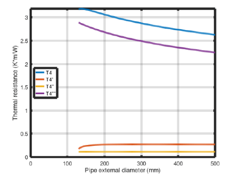
The analyses of thermal resistances T4, T4’, T4“, T4“‘ in expression (2), heat transfer mechanisms Wt, Wconv,s, Wcond, Wrad,s-w in expressions (4)–(7), and the resulting cable ampacity were performed for conditions given in Fig. 4 and Table 1. With regard to the dimensions of the pipe-type duct, it should be mentioned that the standard dimensional ratio (external pipe diameter to pipe wall thickness ratio) is equal to 11 – it is marked SDR11. The results of the performed analyses, shown in Figs 6–8, have revealed that:
• The thermal resistance T4’ of the medium (air) inside the duct is constant (Fig. 6), which confirms the conclusion regarding T4’ from the previous section.
• The thermal resistance T4” across the wall of the duct (Fig. 6) is constant due to the constant value of the external/internal diameter ratio for the pipe/duct [17].
• The external thermal resistance T4“‘ (Fig. 6) decreases with the increasing pipe diameter.
• The share of heat dissipation by convection Wconv,s increases with the increasing pipe diameter (Fig. 7), due to more intensive air flow in the pipe/duct.
• For pipes/ducts with relatively small diameter, heat dissipation through conduction plays an important role (Wcond in Fig. 7).
• For larger pipe/duct diameters (160 mm or more), the heat dissipated by thermal radiation (Wrad,s-w in Fig. 7) gives around 70% share (Wrad,s-w/Wt) in total heat dissipation.
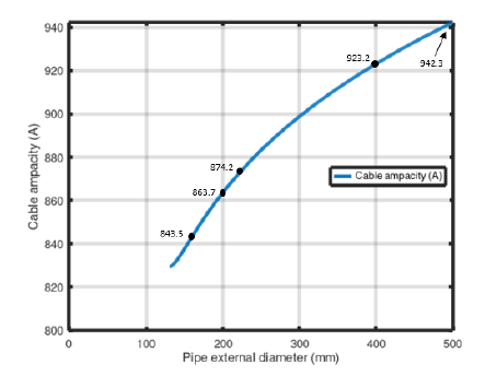
Consequently, the larger the diameter of the pipe in which the cable is placed, the higher its ampacity (Fig. 8).
When installing a cable in a pipe-type duct, the internal duct diameter is usually at least 1.5 times larger than the external diameter of the cable [18, 19]. For the investigated case, when the cable external diameter is 99.08 mm (see Table 1), the normalized pipe of PE200, SDR11 or larger should be used (the pipe internal diameter is 163.6 mm and it gives the diameter ratio 163.6/99.08 ≥ 1.5). Such a diameter of the pipe/duct results in the ampacity equal to 863.7 A (see Fig. 8). The increase of pipe diameter to 400 mm gives the ampacity equal to 923.2 A (ampacity increase by around 7%).
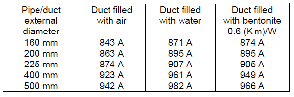
The above investigation of power cable ampacity has been validated with CYMCAP software [20]. Comparing the results from the analytical approach (Fig. 8) with those obtained from the software-aided calculation (second column in Table 3), it can be concluded that the accuracy is around 1 A.
For a wider comparison of types of duct filling, Table 3 also contains the results of ampacity calculations for ducts filled with water and ducts filled with bentonite. One can observe that, for example, the duct of 160 mm diameter filled with bentonite gives the same ampacity as the duct of 225 mm diameter filled with air. Therefore, in some cases (very long and deep cable ducts), it can be more favourable to use a larger diameter of the air-filled duct (the simplest and cheapest solution) than a smaller diameter duct filled with bentonite or water.
Table 3. The ampacity of the analyzed power cable system in duct for various types of filling calculated with CYMCAP software
Conclusion
The article presents the results of analytical calculations of the ampacity of high-voltage power cables installed in cable ducts. The effect of duct diameter on this ampacity is investigated. The investigation is mainly conducted for cable ducts filled with air, which is the simplest duct arrangement. The results of the analysis have shown that the increase of the diameter of the air-filled duct may give the same ampacity of cables as in the case when the duct of a smaller diameter is filled with water or bentonite. Taking into account problems with effective filling of cable ducts, especially when bentonite is used, for very long and deep ducts the authors recommend the simplest solution: the air-filled duct with properly increased diameter.
REFERENCES
[1] Neher J. H., McGrath M. H., The calculation of the temperature rise and load capability of cable systems, AIEE Transactions, 76 (1957), No. III, 752–772
[2] IEC 60287-1-1:2006 Electric cables – Calculation of the current rating – Part 1-1: Current rating equations (100% load factor) and calculation of losses – General (2006)
[3] Anders G. J., Rating of Electric Power Cables in Unfavorable Thermal Environment, IEEE Press: Piscataway, NJ, USA (2005)
[4] Anders G. J., Rating of Electric Power Cables Ampacity Computations for Transmission, Distribution, and Industrial Applications, McGraw–Hill: New York, NY, USA (1997)
[5] de Leon F., Major factors affecting cable ampacity, IEEE Power Engineering Society General Meeting (2006)
[6] De Mey G., Xynis P., Papagiannopoulos I., Chatziathanasiou V., Exizidis L., Wiecek B., Optimal position of buried power cables, Elektronika ir Elektrotechnika, 20 (2014), 37–40
[7] Liang Y., Zhao J., Du Y., Zhang J., An optimal heat line simulation method to calculate the steady-stage temperature and ampacity of buried cables, Przeglad Elektrotechniczny, (2012), No. 3b, 156–160
[8] Maśnicki R., Heat dissipation from the cable in underground power lines, Przeglad Elektrotechniczny, 97 (2021), No. 5, 74–77
[9] Czapp S., Ratkowski F., Optimization of thermal backfill configurations for desired high-voltage power cables ampacity, Energies, 14 (2021), No. 5, 1452, https://doi.org/10.3390/en14051452
[10] Balzer C., Hinrichsen V., Drefke C., Stegner J., Sass I., Hentschel K., Dietrich J., Improvement of ampacity ratings of Medium Voltage cables in protection pipes by comprehensive consideration and selective improvement of the heat transfer mechanisms within the pipe, Jicable’15 (2015), F2-19, 1–6
[11] Ariaratnam, S., Koo, D. H., & Dyer, M. L., Thermoconductivity effects on electrical installations using horizontal directional drilling. In International Society for Trenchless Technology – 25th No-Dig International Conference and Exhibition, Roma 07: Mediterranean No-Dig (2007), 478–486
[12] HEKOTERM Material technical sheet, Hekobentonity (2017)
[13] IEC 60287-3-1:2017 Electric Cables – Calculation of the Current Rating – Part 3-1: Operating conditions–Site Reference Conditions (2017)
[14] Czapp S., Ratkowski F., Effect of soil moisture on current-carrying capacity of low-voltage power cables, Przeglad Elektrotechniczny, 95 (2019), No. 6, 154–159, doi:10.15199/48.2019.06.29
[15] International Council on Large Electric Systems, CIGRE. A Guide for Rating Calculations of Insulated Cables. Working group B1.35, CIGRE: Paris, France (2015)
[16] Ratkowski F., Analiza obciążalności prądowej długotrwałej linii 110 kV RPZ Powiśle – RPZ Stadion na podstawie danych DTS, XXVI Konferencja Szkoleniowo-Techniczna „Elektroenergetyczne sieci kablowe i napowietrzne KABEL 2019”, Janów Podlaski (2019)
[17] IEC 60287-2-1:2001 Electric Cables–Calculation of the Current Rating–Part 2-1: Thermal Resistance–Calculation of the Thermal Resistance (2001)
[18] Hemant J., Residential, Commercial and Industrial Electrical Systems: Equipment and Selection, Volume 1, McGraw Hill Education (India), (2008)
[19] N SEP-E-004 Elektroenergetyczne i sygnalizacyjne linie kablowe. Projektowanie i budowa (2014)
[20] CYMCAP – software for power cable ampacity rating
[21] International Council on Large Electric Systems, CIGRE. Long Term Performance of Soil and Backfill Systems, Working group B1.41, CIGRE, France (2017)
[22] Jakubowski J., Cichy A., Rakowska A., Wytyczne projektowania linii kablowych 110 kV, PTPIREE (2019)
Authors: mgr inż. Filip Ratkowski, Research & Development Center, Eltel Networks Energetyka SA, Gutkowo 81 D, 11-041 Olsztyn, Poland, E-mail: filip.ratkowski@eltelnetworks.com mgr inż. Michał Kołtun, Research & Development Center, Eltel Networks Energetyka SA, Gutkowo 81 D, 11-041 Olsztyn, Poland, E-mail: michal.koltun@eltelnetworks.com dr hab. inż. Stanisław Czapp, prof. PG, Gdańsk University of Technology, ul. G. Narutowicza 11/12, 80-233 Gdańsk, Poland, E-mail: stanislaw.czapp@pg.edu.pl
Source & Publisher Item Identifier: PRZEGLĄD ELEKTROTECHNICZNY, ISSN 0033-2097, R. 98 NR 3/2022. doi:10.15199/48.2022.03.32
