Published by Piotr ZEGARMISTRZ, Bartłomiej GARDA, AGH University of Science and Technology
Abstract. The aim of the research presented in a paper was to provide trustworthy simulation results for symmetrical three-phase systems with memristive load. The memristors in the system are combined with linear resistors in order to limit the current in the element. Linear drift model of the memristor was considered in Matlab simulations. It is based on Strukov model with Biolek window. High nonlinearity of memristor results in deformation of most of the signals in the system. Since the voltage of the neutral point is highly non-sinusoidal it affects on other signals like phase voltage, phase currents, delta voltages. A Fast Fourier Transform (FFT) is applied to chosen signals in order to provide a frequency spectrum. On this basis a Total Harmonic Distortion (THD) parameter was calculated.
Streszczenie. W pracy zaprezentowano wyniki badan´ symulacyjnych nad układem trójfazowym symetrycznym z obcia˛z˙eniem elementami memrystorowymi. Memrystory w obwodzie odbiornika sa˛ poła˛czone szeregowo z rezystorami liniowymi w celu ograniczenia pra˛du. W obliczeniach symulacyjnych przyje˛ to model memrystora “linear drift”, bazuja˛cy na modelu Strukova z oknem Biolka. Wysoka nieliniowos´c´ elementów memrystorowych skutkuje odkształceniem wie˛kszos´ci sygnałów w obwodzie. Skoro napie˛cie punktu neutralnego odbiornika wykazuje wysoka˛ nieliniowos´c´, to skutkuje to odkształceniem pozostałych sygnałów, t.j. napie˛c´ fazowych, pra˛dów fazowych czy napie˛c´ przewodowych. Do wybranych sygnałów zastosowano Szybka˛ Transformate˛ Fouriera (FTT) w celu zaprezentowania widma cze˛stotliwos´ciowego. Na tej podstawie obliczono Współczynnik Zawartos´ci Harmonicznych. (Elementy memrystorowe w układach trójfazowych)
Keywords: memristor, memristive device, memristive element, three-phase systems, nonlinear systems
Słowa kluczowe: memrystor, element memrystorowy, układy trójfazowe, obwody nieliniowe
Introduction
Theoretical definition of memristor was stated by L.O. Chua in 1971 [1][2]. It was defined as an element in which the actual value of resistance depends on the flux or charge through the element. It is capable of switching between two resistance states upon application of an appropriate voltage or current signal that can be sensed by applying a relatively much smaller sensing signal [3]. It was announced as the missing fourth fundamental passive circuit element.
In 2008 HP Laboratories reported the discovery of the element, which exhibits electrically controllable state dependent resistance [3][4]. It was a turning point in research on memristive devices. This topic became a priority for many R&D units and academic researchers. The most crucial property of memristor is the fact, that it can take two significantly different values of resistance in a stable way. This explains, why after 2008 this topic became so popular for scientists specializing in electronics, in particular memories, logic circuits and neuromorphic systems [5].
However, the applications of memrsitive devices focuses on microelectronics, that is not the one and only correct direction. In recent years the concept of so-called ’power memristor’ grows. The idea is to use memristive elements in lightning protection systems, i.e. instead of traditional varistors. In [6] author proposes a combined over-voltage protecting device consisting of a memristor connected in series with a spark gap. The memristor is applied for dissipating lightning surge energy and for breaking the short circuit current. This simple example shows, that analyzing the usage of memristive device in three-phase systems is noteworthy and can deliver a basis for further research.
A characteristic pinched hystersis loop (so-called bowtie curve) in v-i relation when applying a sinusoidal voltage to the element is also a special mark for memristors. This v-i histeresis loop always passes through the origin for any bipolar periodic input voltage [7]. The shape of the curve narrows down signifficantly with the frequency f. Beyond a certain critical frequency, the area of the loop decreases monotonically. It aims to zero with the frequency f increasing [8]. In this work, the authors decided to analyze the possibility of a usage of two-terminal memristive devices in threephase systems. It is assumed, that the system is powered by symmetrical three-phase source (i.e. set of three sinusoidal voltage sources with the same amplitude and phase shifted by 2π/3 ) and it is loaded by serial connection of a memristor and linear resistor with the value appropriate to limit the current in the memristive element in such a way that it is set in its work area. The basic aim of this study was to deliver a trustworthy information about the behavior of the signals in a three-phase system when memristive devices occur. To simplify the case study, it is limited to the symmetrical load version. The next aim was to analyze the impact of increasing frequency f of the input signal on the signals in the system.
Linear Ion Drift Model
This model is also known as Strukov model. It is assumed, that oxygen ions drift through the memristor structure with the velocity that depends linearly on the electric field. The v-i (voltage-current) relation in this model is:
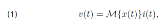
where M{x(t)} = Ronx(t)+Roff(1−x(t)) represents the memristance of the memristive element in Ohms.
The internal variable x(t) denotes the relative width of the low-resistance region. Its dynamics is defined by the following formula:
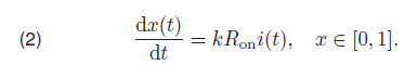
To ensure that internal variable x(t) is confined to the interval [0, 1] one can multiply the right hand side of the equation above (2) by the ideal rectangular window function defined as f(x) = 1 for x ∈ [0, 1] and f(x) = 0 for others.
The above model depends on three parameters. Ron and Roff are the minimal and maximal resistances of the element, while the parameter k represents material properties and geometrical structure of the element.
Biolek Window Function
The equation (2) defining the elements dynamics does not take into account the physical phenomenon that switching mechanism is slower while states variable is close to the border of the limiting interval. One of the method that introduces this phenomenon is the window function application.
Then the equation (2) becomes:
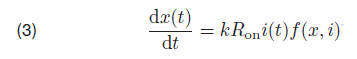
where the f(x, i) is the mentioned window function of internal variable x and current i across the element. One of the popular window function is proposed by Biolek et al. [9], where the function f(x, i) is defined as:

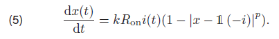
where p is an even integer and 1 (·) represents a unit step function.
In this work a modified version of Biolek window is used, in which the absolute value of the expression under the power p is taken [10]. This permits using odd values of p also. Than, the Strukov model with the Biolek window is defined as:
The window function (4) introduces an additional integer parameter p to the Strukov model.
Simulations
All the simulations, results of which are presented in section below, were carried out in Matlab environment. Prepared simulation software gives the opportunity to measure and plot all of the signals in three-phase system, ie. voltage of the neutral point, phase voltages, phase currents, delta voltages and neutral wire current. It is possible to simulate both three-cord and four-cord systems, but in this paper only results for three-cord system are presented. The diagram of the circuit considered in the simulations is shown on Fig. 1. User can also set the specific value of phase wire resistance, as well as neutral wires resistances for four-cord case. Simulations for non-symmetrical loads, as well as for non-symmetrical three-phase sources are also possible. One can set an amplitude and phase shift for each phase voltage source separately. But this opportunity is not taken into account in this paper.

Results of the simulations for different frequencies are described in section below. For all simulations Linear Ion Drift Model with Biolek Window was used. This model bases on phenomena, that take place in real memristive element, so it is the most appropriate for that experiments.
Results
The main goal of the experiments was to show, how theoretically symmetric three-phase system behaves in terms of existing non-linear memristive elements. The simulations were made for the input phase voltages with RMS value 4V and linear resistance 1kΩ in series to memristor in order to limit the current in the element the same way, like in real measurements.
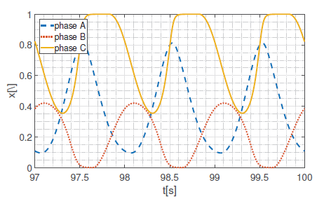

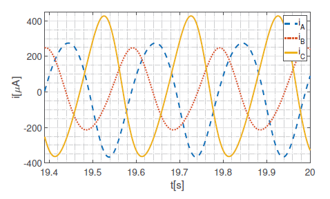
In this paper we focus on experiments made for the three-cord system. The frequency of input signals varies from 1 Hz to 500 Hz. Fig. 2 to 7 present the output parameters of the system for the frequency 1 Hz. To reduce the influence of the initial parameters all time series presented in the article shows the results of the simulation after some time of evaluation.
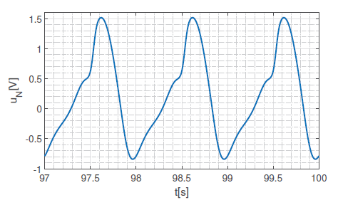
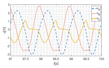
Shape of the internal variable x impacts on actual value of the resistance of memristor. This causes high non-linearity, which reveals in the shape of neutral point voltage signal. Since it is non-sinusoidal, all other signals in the system are non-sinusoidal. It is not obvious to find any conclusions for that results, but surely one can observe, that signals of the phase B are deformed in least significant way. This is confirmed in the shape of v-i curve (hysteresis loop), which is less pinched for phase B, than for the others. It is interesting that this phenomenon does not depend on different initial states values.
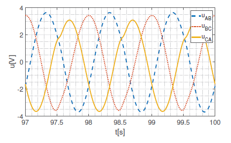

Delta voltages (line voltages) are measured between connection nodes of linear resistor and memristor in each phase. Clearly, they are less deformed than other signals. An interesting observation may occur, when analyzing a frequency spectrum of the reported signals. In order to achieve it, the authors propose to perform a FFT (Fast Fourier Transform) on the signals. An answer of FFT for a chosen signal (phase A current) is shown on Fig. 8. It is important to notice the DC factor which value is on the level of second harmonic frequency. As it was mentioned earlier, the experiments were lead for wider range of frequencies.
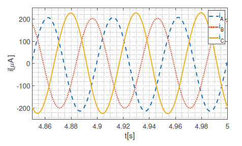
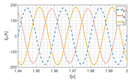
As it is impossible to present graphs for all measured signals, authors decided to compare only chosen signals for higher frequencies – phase currents and v − i relation.
As one can see, the higher frequency, the more linear behavior of the memristive element. For frequencies 100 Hz and higher, the system behaved like fully linear system, so presenting graphs for them seems to be pointless. The general rule observed is, that the shape of the pinched hysteresis loop narrows down with increasing the frequency. For frequencies 500 Hz and higher it is straight line, so the memristor behaves as regular linear resistor.

Conclusions
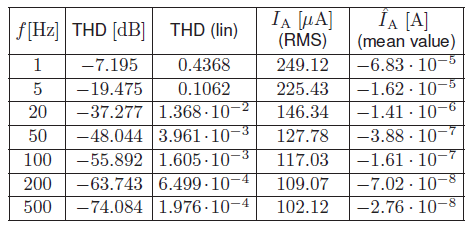
The authors performed also simulation results for four-cord systems, but because of limited space, it will be published in separate paper in near future. Presented results confirm the theoretical evidence, that memristor v − i characteristic tends to linear with increasing frequency. Moreover, for lower frequencies high non-linearity is observed. It motivated the authors to calculate a Total Harmonic Distortion (THD) parameter for chosen signals in order to show the degree of deformation of the signal versus frequency. In Tab. 1 the results for phase current iA are presented. Furthermore Tab. 1 contains RMS and mean values of iA. It is worth to notice that for low frequency f = 1Hz the value of the current is ca. 2.5 times higher than for the higher frequency f = 500 Hz. Also interesting is the fact of presence of DC factor which also tends to zero when the frequency increases.

In future work the measurements on real three-phase systems with memristive load is planned. Experimental research is the natural way to verify the results of analytical simulations. In order to achieve this a precise phase-shifting module needs to be design and build.

Table 1. Basic parameters of phase A current iA vs frequency f
Acknowledgment: This work was supported by the National Science Centre, Poland, grant no. 2015/17/B/ST7/03763.
REFERENCES
[1] Chua L. O.: Memristor. The missing circuit element, IEEE Trans. Circ. Theory, vol. 18, no. 5, pp. 507–519, 1971.
[2] Chua L. O.: The fourth element, Proc. IEEE, vol. 100, no. 6, pp.1920–1927, 2012.
[3] Gandhi G., Aggarwal V., Chua L. O.: The first radios were made using memristors!, IEEE Circuits and Systems, vol. 13, no. 2, pp. 8–16, 2013.
[4] Strukov D., Snider G., Steward D., Williams R.,: The missing memristor found, Nature, vol. 453, no. 7191, pp. 80–83, 2008.
[5] Sacchetto D., Gaillardon P.-E., Zervas M., Carrara S., De
Micheli G., Leblebici Y.: Applications of Multi-Terminal Memristive Devices: A Review, IEEE Circuits and Systems, vol. 13, no. 2, pp. 23–41, 2013.
[6] Horváth I.: Simulation of a memristor-spark-gap model for lightning protection purposes, Tehnicki Vjesnik, vol. 21 (5), pp.1047–1050, 2014.
[7] Pickett M., Strukov D., Borghetti J., Yang J., Snider G., Stewart D., Williams R.: Switching dynamics in titanium dioxide memristive devices, Journal of Applied Physics, vol. 106, 074508, 2009.
[8] Adhikari S., Sah P., Kim, H.,Chua L.O.: Three fingerprints of memristor, IEEE Trans. on Circ. and Syst. I: Regular Papers, vol. 60, no. 11, pp.3008–3021, 2013.
[9] Biolek Z., Biolek D., Biolkova B.: Spice model of memristor with nonlinear dopant drift, Radio Eng., vol. 18, no. 2, pp. 786–790, 2015.
[10] Garda B., Galias Z.: Modelling sinusoidally driven selfdirected channel memristors, Proc. ICSES 2018, Cracow, Poland, pp.19–22, 2018.
Authors: Ph.D. Piotr Zegarmistrz, Ph.D. Bartłomiej Garda, Department of Electrical and Power Engineering, Faculty of Electrical Engineering, Automatics, Computer Science and Biomedical Engineering AGH University of Science and Technology, al. Mickiewicza 30, 30-059 Kraków, Poland, email: pzegar@agh.edu.pl; bgarda@agh.edu.pl
Source & Publisher Item Identifier: PRZEGLA˛D ELEKTROTECHNICZNY, ISSN 0033-2097, R. 96 NR 1/2020. doi:10.15199/48.2020.01.03
