Published by Zia Hameed1, Muhammad Rafay Khan Sial2, Adnan Yousaf3, Muhammad Usman Hashmi,
Faculty of Engineering and Technology, Superior University, 17-km off Raiwind Road Lahore Pakistan
Emails: zia.hameed@superior.edu.pk, rafay.khan@superior.edu.pk, adnan.yousaf@superior.edu.pk
Abstract—Power System Harmonics is a real point of concern for Electrical Engineers. In power systems, non-linear loads are permanently connected, unlike transients and other distortions are produced. Due to non-linear loads, distortions are produced in the sinusoidal waveform so active shunt filter is used in parallel with the load to minimize these distortions and in a result pure sinusoidal waveform is obtained. Active shunt filter is work as a current source, but opposite in phase sequence to the current which produces by non-linear loads. Harmonics is an all-time problem. Relay protection devices are not good enough to resolve this problem, so other techniques are to be studied to minimize their effects. In this paper my major concern is to identify the loads which causes harmonics, how to design a filter for removing harmonics their effects on power systems, how to design a filter for removing harmonics, proposition of useful filters for altered types of loads and their simulation on ETAP (Electrical Transients and Analysis Program).
Keywords — AC wave, Even Harmonics, Filters, Odd Harmonics, Linear and non-linear loads, ETAP.
I. INTRODUCTION
Service dependability and worth of power have become growing consternations for many capacity directors, especially with the increasing sensitivity of electrical equipment and programmed controls[4]-[6]. There are several types of voltage variations that can cause anomalies, including surges and spikes, sags, harmonic distortion, and temporary disruptions. Harmonics can cause sensitive equipment to failure and other problems, as well as overheating of transformers and wiring, irritation breaker trips, and a bridged power factor[2], [11].
The part of distribution of electric voltages to the power system is very important. This objective is difficult due to Harmonics currents that are produced [9]. They produce harmful effect on the system and disturb its continuity. So when harmonics are produced it is necessary to reduce it for better performance of the system. There are two concepts for which we can understand, how harmonics affect the power system [2], [10]. Firstly, the harmonics are produced due to non-linear loads and the second is that how harmonics current flow and produce harmonic voltage [6].
II. HISTORY
In 1888, Tesla familiarized the concept of poly-phase systems after that in 1890, at Portland, Ore a 1st power transmission line of length 13 miles at frequency of 132 Hz was setup [1], [2]. In the same year, Bedell studied the field of alternating current and also studied the effects of alternating current wave forms in power systems [2], [3]. In 1893, at Hartford engineers dealing with a heating problem of a motor had selected harmonics analysis as a technique to identify the causes of motor heating and tried to solve the problem[3], [4]. Steinmetz discouraged the use of high frequency in power systems because of the high transmission line resonance [6]. It was noticed that the voltage wave form having frequency 133 Hz or 125 Hz was plentiful in harmonics. Steinmetz suggested two solutions for the removal of higher harmonics. First was to reduce the system frequency of 133 Hz or 125 Hz to half i.e. 66.5 Hz or 62.5 Hz. The second suggestion was to refit the iron laminations in the motor which can bear higher in-service voltage [1], [2]. In 1895 generator manufacturing companies Westinghouse and GE presented such generators having distributed armature winding to make the waveform more sinusoidal. It was also noted that when two generators operate in parallel and solidly grounded excessive neutral current flows which causes harmonics. 3rd harmonic was reduced by changing armature winding pitch factor when the neutral of a machine was solidly grounded [3], [5]. In 1910 telephone interference factor was given great importance even in 1980s it was included in the standards due to the large usage of mercury arc rectifier which is a large source of this distortion. In 1960s, in instruction to progress power factor and to reduce the power system harmonics large number of shunt capacitors and filter banks were installed in industrial power systems. In 1812, Jean Fourier developed a mathematical way to analyze the complex functions [1], [2]. This technique expands the complex functions into sine and cosine functions. Harmonics analysis is the name given by Thomson and Tait [1]-[3]. Bernoulli, Euler and Maxwell also used this technique in 18th century. In 1966, J.W Coley and J.W Tuky suggested the Fast Fourier Transform (FFT) as a technique for computer code so that it can give results hurriedly. IEEE standard 519 is now the principle interface standard used by most engineers to judge harmonics issues [3], [4].
III. HARMONIC CONCEPTS
Due to distortion of voltage and current waveform harmonics are produced. Harmonics are mentioned to be a section of a waveform that is the integral multiple of the fundamental frequency. If the load is inserting normal power back to the source at harmonic frequencies, it can be called a Harmonic source.

IV. LINEAR AND NON-LINEAR LOADS
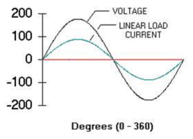
In a power system, current waveform is same as voltage because current is proportional to voltage. Examples of linear loads are heaters and motors.
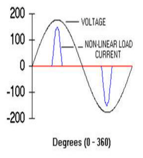
But for Non-linear loads the current and voltage waveform are different. Examples of non-linear loads are UPS and DC motor drives.
The current waveform is not periodic but it remains same cycle to cycle. Due to sum of sinusoidal waves, periodic waves are generated.
V. VOLTAGE AND CURRENT HARMONICS
The expression ‘harmonics’ is often used by itself without further qualifications. However, the voltage and current harmonics are separate in their effects and are also mutually related. Non-linear loads at the consumer end appear to be injecting the harmonic currents in the power system. For this reason, they are normally treated as harmonic current sources. On the other hand, the harmonic voltages are the result of harmonic current times the linear impedances of the control system. The harmonic current passing through the system resistances causes the voltage drop across it which results in voltage harmonics. Thus, the voltage harmonics are the function of current harmonics and the linear impedances of the power system.
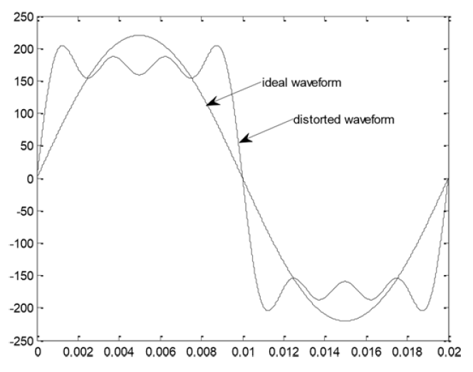
Fig.4 shows a voltage waveform of peak value equal to the secondary distribution level of Pakistan i.e. 220 V. Likewise, it also depicts the harmonics mechanisms with amplitudes of (1/3) to (1/5) and (1/5) to (1/7) of 220V and having the frequencies three, five and seven times the essential frequency correspondingly. Assuming the voltage harmonics are due to the passage of harmonic current through a system resistance.

VI. COMPARISON BETWEEN TRANSIENTS AND HARMONICS
Transients and Harmonics often cause confusion and most of the times one is blamed instead of the other for a particular quality disturbance in power system. The main differences between harmonics and transients are shown in the Table 1.
Table 1: Comparison between Transients and Harmonics
VII. EVEN AND ODD HARMONICS
Harmonics are fundamentally the integral multiples of the fundamental frequency. Even harmonics are the even multiples and odd harmonics are odd multiples of the fundamental frequency.
Even harmonics: 2𝑓,4𝑓,6𝑓,…,2𝑛𝑓
Odd harmonics: 3𝑓,5𝑓,7𝑓,…,(2𝑛+1)𝑓
here, 𝑛 is a natural number.
Similar waves contain only odd harmonics but odd and even both harmonics are produced due to asymmetrical waves.
In odd harmonics both positive and negative parts of the wave are same but in asymmetrical waves both positive and negative parts are different. Asymmetrical wave is the result of half wave rectifier.
Control scheme produces only odd harmonics. This is due to same waves. Due to this reason, only odd harmonics will be discussed in upcoming sessions.
VIII. HARMONICS PHASE SEQUENCE
In order to describe a physical three phase system, Power Engineers have adopted a technique of balanced machineries which is based on Fortescue’s theorem. That is stated as:
“An unstable set of 𝑛 phasors may be resolute into (𝑛−1) stable n-phase systems of diverse phase sequence on one zero-phase sequence system.”
Phase sequence of the phasors is the order in which they pass through a positive maximum. A physical 3-phase system with phases A-B-C can be resolved into following three component sets of balanced phasors:
• Positive-sequence contains three sinusoids which are at 120𝑜 from each other.
• Negative-sequence contains three sinusoids which are at 120𝑜 from each other and they are opposite to the positive sequence.
• Zero-sequence contains three sinusoids that are in-phase with each other.
So for second harmonic, 𝑛=2 we get 2×(0𝑜,−120𝑜,120𝑜) 𝑜𝑟 2×(0𝑜,120𝑜,−120𝑜)
It shows negative sequence.
For third harmonic, 𝑛=3 we get
3×(0𝑜,−120𝑜,120𝑜) 𝑜𝑟 (0𝑜,0𝑜,0𝑜), which is the zero sequence. Here is the detail of only odd harmonics:
• 𝑛= 1,7,13,… +𝑣𝑒 𝑠𝑒𝑞𝑢𝑒𝑛𝑐𝑒
• 𝑛 =5,11,17 … −𝑣𝑒 𝑠𝑒𝑞𝑢𝑒𝑛𝑐𝑒
• 𝑛 =3,9,15 … 𝑧𝑒𝑟𝑜 𝑠𝑒𝑞𝑢𝑒𝑛𝑐𝑒
Harmonics of order 𝑛=3,9,15 … are also named as Triplens. They deserve special consideration because of their critical nature and considerable effects on the behavior of the power system. They are of much importance while discussing grounded-star system containing the neutral current. The two main problems associated with triplens are:
• Overloading of the neutral
• Telephone interference
Due to the triplen harmonics, an excessive current flows through the neutral conductor resulting in the overloading of neutral. Among the triplen harmonics, 3rd Harmonic got the much consideration of power engineers.
IX. MEASURING PARAMETERS OF HARMONICS
The result of harmonics is measured by the following methods.
a) Total Harmonics Distortion
Total Harmonic Distortion is identified by Harmonic Distortion Factor which is the most common technique to calculate harmonics distortion of current and voltage. For an ideal system, THD is equal to zero. THD is determined by:
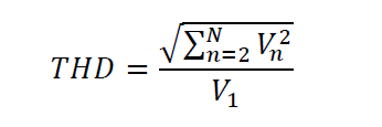
𝑉𝑛 is the rms voltage at harmonic, 𝑁 is the maximum harmonic order and 𝑉1 is the line to neutral rms voltage.
b) Total Demand Distortion
THD can also be applied to study the current distortion stages but in the case of low fundamental load current, it can be deceiving. A small current may carries high THD which is danger for system. For example speed drives shows the high THD values at very light loads for any value of input current. The magnitude of harmonic current is low. This high THD value for input current is not considerable concern even though its comparative distortion to the fundamental frequency is high.
TDD is scientifically calculates:
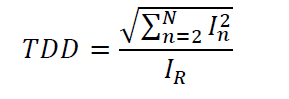
Where 𝐼𝑅 is the peak hours demand load current at the fundamental frequency component determined at point of joint coupling (PCC). There are two ways of calculating 𝐼𝑅. With the load which is already in the system, it can be determined simply by averaging the peak demand current for the preceding 12 months.
X. SOURCES OF HARMONICS
Due to non-linear loads and switching processes harmonics distortion is produced. These sources of waveform can be found in engineering installation in thousands of KVA value. The main sources of harmonics in power system are:
• Due to windings in the transformer and magnetic capacity in stators and rotors of Electrical machines
• In the transformer core due to magnetic saturation
• Due to rectifiers and inverters
• Due to nonlinear loads
A. Rotating Machines
Revolving machines become a source of harmonic distortion because of irregularities in stator and rotor slots or due to winding patterns. So these harmonics produce emf. But these harmonics are very less in quantity as compared to variable speed drives.
B. Transformer
An excessive magnetic flux is produced through the core when transformer operates near the saturation zone. Due to this excessive magnetic flux, linear rise of the magnetic flux density is limited. Core saturation of transformer is resulted when it operates either:
• Above then the rated power
• Above then the rated voltage
At rated power harmonics are produced due to peak hour voltages. A Transformer is function on a saturation region so non-linear magnetizing current is found which produces odd harmonics and due to hysteresis losses distortion is produced. Distortion is characteristically due to triplen harmonics, but mostly due to the third harmonic. Delta connection is used to restrict the third harmonic current within the transformer. This helps in preserve a supply voltage with a sensible sinusoidal waveform.
C. Power Electronic Converters
There is a large use of Electronic converters in domestic and industrial purposes due to domestic uses. Single phase rectifier is very common converter which is used for domestic and industrial applications but three phase converter is more danger as compared to single phase converter because it produces 3rd order harmonics which are more dangerous for the power system.
D. Arcing Devices
The foremost harmonic sources in this group are the arc welder’s electric arc furnaces, and discharge type lighting (arc furnace, sodium vapor, florescent) for magnetic (rather than electronic) ballasts. Due to arc furnace in industries, harmonics are produced. So when the arc increases, voltage will decrease in the power system.
E. Future Sources of Harmonics
For Electrical system designer it is a challenge that to design such an instrument for domestic uses and industry that operate at harmonic level. Due to very large use of sensitive electrical and electronic devices harmonics are produced so it is very dangerous in the near future. Due to very large use of switching devices and instruments harmonics are produced which are very dangerous in the near future. Due to distributed generators harmonics are produced specially in peak hours.
XI. EFFECTS OF HARMONICS
Harmonics are very dangerous for the remaining power system and the equipment’s that are attached with the power system. The main effects of voltage and current harmonics within the power system are:
• The possibility of amplification of harmonic levels resulting from series and parallel resonances
• Degradation of the power factor
• Overheating of the phase and neutral conductors
• Efficiency of the generators is reduced day by day due to harmonics
• Eddy current and hysteresis losses in transformers
• Overheating of the system components e.g. generators, motors and transformers etc.
• Flow of additional current through power capacitors
• Decrement in the useful lives of the incandescent lamps
• Increase skin and proximity effects
• Interference problem with telecommunication
• Effects the relay protection system
For the adverse effects of harmonics on the power system, it is the major demand of the today’s power system that these harmonics should be mitigated by appropriate designing of the filters either active or passive.
XII. DESIGNING OF FILTERS
Distribution network is a network which is close to the consumers end. Non-Linear loads are attached at the consumer’s end, so mainly Harmonics are produced at the consumers end. So for the removing of Harmonics we used Active shunt filters at the distribution side. Due to non-linear loads reactive current is produced which causes Harmonics. So for removing of reactive current Hysteresis band control method is used to produce trigger signal to the inverter to produce reference current. Due to non-linear loads distortions are produced in the sinusoidal waveform so active shunt filter is used in parallel with the load to minimize these distortions and in a result pure sinusoidal waveform is obtained. Active shunt filter is work as a current source, but opposite in phase sequence to the current which produces by non-linear loads. Similarly filters are also used which work as a voltage source for the removing of Harmonics. When the Harmonics will be removed from the Electrical System then efficiency and life will be increases of the equipment’s. Harmonic current calculator is used for the calculation of Harmonic current, calculator sensed load current and multiply it with unit magnitude of sine and cosine wave, in this way we are able for identify harmonics in the Electrical Power Systems. So Hysteresis bases control circuit is used in the filters for the removing of Harmonics. There are three simulations which are used to filter the Harmonics 1- Simulation of shunt active filter, 2- Simulation of Harmonic current calculator, 3- Simulation of voltage source inverter. But in this paper simulation of shunt active filters is used by using ETAP (Electrical Transient Analyzer Program) software is used. Filters are tuned in such a way that at which frequency they are tuned resonance will be occur and that harmonic content will be filter from the wave.
XIII. ETAP AS A BRILLIANT TOOL FOR HARMONICS ANALYSIS
ETAP is a best tool for the study of harmonics in a power system. With the help of ETAP we can study the Harmonics Analysis of any type of circuit and with the help of ETAP we can also study the Harmonics spectrum. By load flow analysis we can study the harmonics analysis. First of all we study the load flow analysis at the fundamental frequency. With the help of load flow analysis we can study the power factor at different buses in the electrical power system and after that we can check the harmonics analysis and order of harmonic spectrum. By doing the harmonics analysis, low order frequencies are produced.
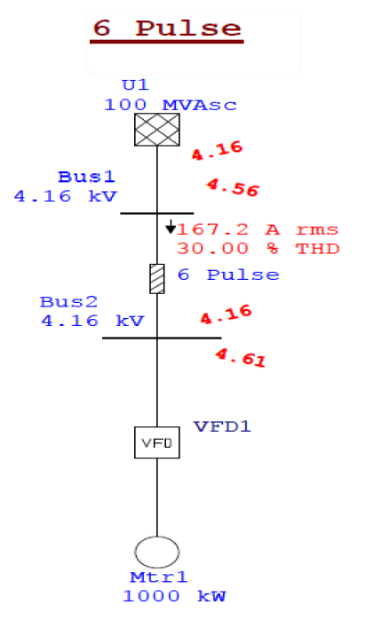
Here we study different cases of “Variable Frequency Drives” using ETAP and observe the effectiveness of this tool.


CONCLUSION
Harmonic distortion is one of the major issues to maintain the power quality. From the results we shown that harmonics are removed by using active shunt filters. Harmonics not only effects the power quality but also cut down the useful life of the power apparatus. It is associated with the major power system components i.e. transformer, synchronous motors, power converter and electrical furnaces. Since these components are continuously connected to the power system, harmonics is all time concern present in the fundamental signal. It is therefore crucial to mitigate this distortion. Harmonics analysis is also very important to study all the effects and the losses which we have to bear. So ETAP (Electrical Transient and Analysis Program) is an important simulation software to check the systems losses and effects before its installation. We conclude that we can check Harmonics Analysis by using ETAP and can be removed by using active shunt filters.
REFERENCES
[1] Edward L. Owen, “A History of Harmonics in Power Systems”, IEEE Industry Application Magazine, Jan/Feb 1998, pp 6-12
[2] P. Berdell,” History of AC wave form, Its determination and standardization”, AIEE, Trans, vol.61, 1942, pp.864-68
[3] S.P. Thompson, “A new Method of Harmonic Analysis by selected ordinate”, Proc. Of the physical society
[4] T. R. Bosela, Introduction to Electrical Power System Technology, New Jersey, Prentice Hall, 1997, pp. 458 462.
[5] Angelo Baggini, Zbigniew Hanzelka, Handbook of Power Quality, John Wiley and Sons Ltd. England 2008, pp. 187 236.
[6] Francisco C. De La Rosa, Harmonics and Power Systems, Distribution Control Systems, Inc. Hazelwood, Missouri, U.S.A. 2006, pp. 1-56.
[7] Roger C. Dugan, Mark F. McGranaghan, Surya Santoso, H. Wayne Beaty, Electrical Power Systems Quality, Second Edition, pp. 167 223.
[8] R. Rexte, “Power Electronic Polluting Effects”, IEEE Spectrum, May 1997, pp. 33 39.
[9] M. Izhar, C. M. Hadzer, S. Masri, S. Idris, “A Study of the Fundamental Principles to Power System Harmonic”, National Power and Energy Conference (PECon) Proceedings, Bangi, Malaysia, 2003.
[10] C. Sankaran, Power Quality, CRC Press LLC.
[11] John J. Grainger, William D. Stevenson, Power System Analysis, McGraw-Hill Companies, Inc. New York, c1994. pp. 417 418.
[12] S. P. Ghosh, A. K. Chakraborty, Network Analysis and Synthesis, McGraw-Hill Education, c2010, pp. 933.
[13] S. L. Clark, P. Famouri, W. L. Cooley, “Elimination of Supply Harmonics”, IEEE Ind. Appl. Magazine, March 1997.
[14] E. B. Makram, R. B. Haines, A. A. Girgis, “Effect of Harmonic Distortion in Reactive Power Measurement”, IEEE Trans. Ind. App., vol. 28, no. 4, July 1992.
[15] Control of Harmonics in Electrical Power Systems, American Bureau of Shipping, May 2006, pp. 29 48.
[16] L. Cividino, “Power Factor, Harmonic Distortion; Causes, Effects and Considerations”, IEEE Telecommunications Energy Conference INTELEC 92, 14th International, Oct. 1992, pp. 506 513.
[17] Jos Arrillaga, Bruce C. Smith, Neville R. Watson, Alan R. Wood, Power System Harmonic Analysis, University of Canterbury, Christchurch, New Zealand, pp. 7 25.
[18] W. M. Grady, R. J. Gilleskie, “Harmonics and how they relate to Power Factor”, IEEE San Diego, Nov. 1993, pp. 1 8.
[19] IEEE Harmonics Modeling and Simulation Taskforce, “Modeling and simulation of the propagation of harmonics in electric power networks part I”, IEEE Trans on power delivery, vol.11, no. 1 , Jan 1996, pp.466-474.
[20] A. Median, “Harmonic simulation techniques (Methods and Algorithms)” IEEE Power Engineering Society General Meeting , Vol.1 , June 2004, pp.762-765
[21] Pravin Chopade and Dr. Marwan Bikdash, “Minimizing Cost and Power loss by optimal placement of capacitor using ETAP”, IEEE 2011 pp.24-3
Author: Zia Hameed was born in 1991 in Bahawalpur, Pakistan. He is doing his Graduation in Electrical Power Engineering from The Islamia University of Bahawalpur (2010-14). He contributed his part in this project work especially in the sources and effects of Harmonics. He also played a major role in the study of Filters. He complete different Electrical courses from best worldwide universities like MIT, Delft institute, University of Toronto. Currently he is serving as a Lab Engineer at Electrical Engineering Department of Superior University, Lahore.
Contact: +92-343-7177273
Email: zia.hameed@superior.edu.pk
Source & Publisher Item Identifier: Conference Paper · February 2016. https://www.researchgate.net/publication/313129662
