Published by Elspec LTD, website: elspec-ltd.com
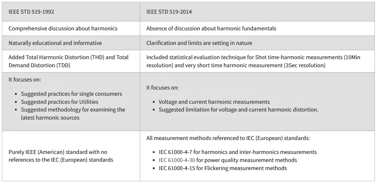
The IEEE 519-2014 standard defines the voltage and current harmonics distortion criteria for the design of electrical systems. The existed voltage and current waveforms in every part of the system are explained in this standard, and the waveform distortion goals for the system designer are established. The standard is periodically updated as the industry evolves. Since its introduction in 1981, the standard has been updated several times and its latest edition is IEEE 519-2014. Some updates have been made by 2022 (see here). The main terms definitions and statistical evaluation technics are being covered within this current article, as the main changes that have been made in the standard were described in the IEEE-519 2014 edition.
Definitions of Important Terms in the IEEE 519
To understand this document’s aim, the meaning of the following terms applied in this document is written below. The IEEE Standards Dictionary Online should be consulted for other terms not defined below.
1. New Definitions
Maximum demand load current: This current value is enacted at the point of common coupling (PCC) and calculates as the average of the currents corresponding to the peak demand during the previous 12 months.
Notch: A condition, lasting less than ½ cycle, in which the magnitude of the voltage waveform reversed its normal polarity.

Point of common coupling (PCC): the point on a public power supply system, electrically closest to a specific load, other loads are, or maybe connected. The PCC is a point located upstream of the regarded installation.

2. Redefined Definitions
Short-circuit ratio: in a specific location, the rate of the available short-circuit current, to the load current, in amperes.
Total demand distortion (TDD): The ratio of the root mean square of the harmonic content, including the harmonic components up-to the 50th order. Expressed as a percent of the maximum demand current. Inter-harmonics are specifically excluded. Higher frequencies (harmonics greater than 50) may be added when required.
Total harmonic distortion (THD): The ratio of the root mean square of the harmonic content, including the harmonic components, up-to the 50th order. Expressed as a percent of the fundamental. Inter-harmonics are specifically excluded. Higher frequencies (harmonics greater than 50) may be added when required.
3. Legacy definitions
Harmonic (component): An element of order more than one of the Fourier series of a periodic quantity. For instance, in a 60 Hz system, the harmonic order 3, commonly known as the “third harmonic,” is 180 Hz.
Inter-harmonic (component): Refers to the frequency component of a periodic quantity that isn’t an integer multiple of the frequency in which the supply system operates (for instance, 50 Hz or 60 Hz).
I-T product: The inductive influence is expressed as regards the product of the root-mean-square current magnitude (I), in amperes, times its telephone influence factor (TIF).
kV-T product: Inductive influence expressed as regards the product of root-mean-square voltage magnitude (V), in kilovolts, and times its telephone influence factor (TIF).
Notch depth: The average depth of the line voltage notch from the sine wave of voltage.
Notch area: It is the area of the line voltage notch. It is the product of the notch depth, in volts, times the width of the notch measured in microseconds.
Pulse number: The total number of successive non-simultaneous commutations taking place inside the converter circuit during every cycle when operating without phase control. It is also equal to the principal harmonic order in the direct voltage, i.e., the number of pulses available in the dc output voltage in one cycle of the supply voltage.
Telephone influence factor (TIF): For a voltage or recent wave in an electric supply circuit, the ratio of adding the square root of the squares of the weighted root-mean-square values of every one of the sine-wave components (with alternating current waves both fundamental and harmonic) to the root-mean-square value (unweighted) of the whole wave.er loads are, or maybe connected. The PCC is a point located upstream of the regarded installation.
Differences with the Previous Edition
New Measurement Method and Statistical Evaluation Technique
The IEEE 519-2014 introduce a newly measurement methods and statistical evaluation technique to determine compliance with the recommended limits.
Harmonics Measurement Methods
The standard adopt the 10/12 cycles gapless harmonic subgroup measurement from the IEC 61000-4-7. Aggregations of 150/180 cycles (~3sec) and 10min are required for the statistical assessments.
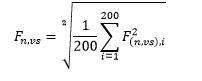
Very short time harmonic measurements: Very short time harmonic values are assessed over a 3-second interval based on an aggregation of 15 consecutive 12 (10) cycle windows for 60 (50) Hz power systems. Individual frequency components are aggregated based on an RMS calculation as shown in Equation (1) where F represents voltage (V) or current (I), n represents the harmonic order, and i is a simple counter. The subscript vs is used to denote “very short.” In all cases, F represents an RMS value.

Short time harmonics measurements: Short time harmonic values are assessed over a 10-minute interval based on an aggregation of 200 consecutive very short time values for a specific frequency component. The 200 values are aggregated based on an RMS calculation as shown in Equation (2) where F represents voltage (V) or current (I), n represents the harmonic order, and i is a simple counter. The subscript sh is used to denote “short.” In all cases, F represents an RMS value.
Statistical Evaluation
Daily evaluation: It is required to calculate the 99th percentile value (i.e. the value that is exceeded for 1% of the day) of the very short time harmonics values for comparison with the recommend limits.
Weekly evaluation: It is required to calculate the 95th and 99th percentile value (i.e. those values that are exceeded for 5% and 1% of the week) of the short time harmonics values for comparison with the recommend limits.
The chart below display a daily accumulative and relative probability chart of the Total Demand Distortion parameter at resolution of 3sec as taken from PQSCADA Sapphire.

The IEEE 519 – 2014 Compliance Criteria
These suggested practice limits are for application at a point of common coupling (PCC) between the system owner or operator and system users. The PCC is often regarded as the point in the power system closest to the user where the system owner or operator could provide services to other users. Usually for service to industrial users, e.g., manufacturing plants through a unique service transformer, the PCC will be at the transformer’s HV side. For most commercial users like office parks, etc., supplied through a usual service transformer, the PCC is commonly at the LV side of the service transformer.
Voltage Distortion Limits
• Daily 99th percentile very short time (3 s) values should be less than 1.5 times the values given in the table below.
• Weekly 95th percentile short time (10 min) values should be less than the values given in the table below.
Table 1. (IEEE 519-2014)

Current Distortion Limits
• Daily 99th percentile very short time (3 s) harmonic currents should be less than 2.0 times the values given in the tables below.
• Weekly 99th percentile short time (10 min) harmonic currents should be less than 1.5 times the values given in tables below.
• Weekly 95th percentile short time (10 min) harmonic currents should be less than the values given in tables below.
Table 2. (IEEE 519-2014) Current distortion limits for systems rated 120 V – 69 kV

Table 3. (IEEE 519-2014) Current distortion limits for systems rated 69 kV – 161 kV

Table 4 (IEEE 519-2014) Current distortion limits for systems rated > 161 kVa

a Even harmonics are limited to 25% of the odd harmonic limits above
b Current distortions that result in a dc offset, e.g., half-wave converters, are not allowed
c All power generation equipment is limited to these vales of current distortion, regardless of actual ISC/IL.
ISC = maximum short circuit current at PCC
IL = maximum demand load current (fundamental frequency component) at PCC
Source URL: https://www.elspec-ltd.com/ieee-519-2014-standard-for-harmonics/
