Published by Marek GAŁA, Andrzej JĄDERKO, Politechnika Częstochowska, Wydział Elektryczny
Abstract. The article presents the principles of measurements and assessment of power quality characteristics, with the power supplied by the micro wind turbine connected to the distribution network. It describes the basic technical parameters of the vertical axis micro wind turbine 10 kW and the characteristics of its output as a function of wind speed. Besides, it shows selected results of measurements of parameters characterizing the power quality in the node of micro wind turbine of 10 kW connection to the 400 V network.
Streszczenie. W artykule przedstawiono zasady pomiarów i oceny jakości energii dostarczanej przez mikroturbinę wiatrową podłączoną do sieci dystrybucyjnej. Opisano podstawowe parametry techniczne mikroturbiny wiatrowej o pionowej osi obrotu i mocy 10 kW oraz charakterystykę jej mocy wyjściowej w funkcji prędkości wiatru. Pokazano również wybrane wyniki pomiarów parametrów charakteryzujących jakość energii w węźle przyłączenia mikroturbiny wiatrowej do sieci dystrybucyjnej 400 V. (Ocena wpływu pracy mikroturbiny wiatrowej na jakość energii elektrycznej w sieci dystrybucyjnej niskiego napięcia).
Keywords: vertical micro wind turbine, power quality, distribution network
Słowa kluczowe: mikroturbina wiatrowa o pionowej osi obrotu, jakość energii, sieć dystrybucyjna
Introduction
The current regulations applicable to non-business energy users state that a microgeneration plant can be connected free of charge to the distribution grid after reporting such an intention to a regional distribution company. Additionally, various funds can be obtained to finance investments into Renewable Energy Sources (RES). These factors are responsible for the visibly growing interest in RES, especially photovoltaic systems and wind turbines, equipped with inverter systems, control systems and protection systems [1, 2, 12].
The massive increase in the number of microgeneration plants can however cause significant problems for the distribution grid, including aggravation of energy quality. Because of this, microgeneration plants connected to the grid should meet a number of technological requirements, as well as conditions specified by grid operators in the relevant instructions, e.g. [9] and [3], in accordance to applicable standards and regulations [4, 5, 6, 10].
In the next sections of this paper characteristics of the wind turbine MEW-10 are presented, followed by selected measurement results of electrical energy quality generated by this unit.
Characteristic of a wind turbine
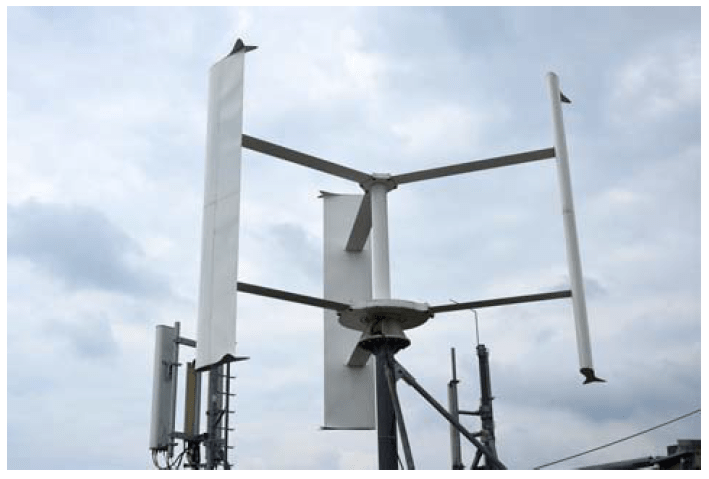
The wind turbine type MEW-10 consists of a vertical axis wind turbine (VAWT) with a three-blade rotor of the H-Darrieus type, a disc slow-rotation permanent magnet synchronous generator (PMSG) and a controller together with protection systems. The rated power obtained by the wind speed 12 m/s is 10 kW. If the wind speed exceeds this value, the power is constrained by the control system [11]. The maximal rotational speed of the rotor is about 140 rpm. A number of empirically obtained characteristics of the MEW-10 are presented in Table 1.
Table 1. Basic characteristics of the MEW-10 wind turbine

The cross-section area of the rotor (wind circle) is 30 m2, with the blade height of 6 m and the rotor diameter of 5 m. A blade cross-section is a symmetrical assembly of standard airfoils type NACA 0021. A wind turbine of the type investigated in the paper is presented in Figure 1.
A power inverter creates current load on the plant generator, which causes torque on the shaft, adjusting the rotational turbine speed to the current wind speed, in this way ensuring the maximal power coefficient. A grid-tie inverter couples the generator with the power grid, generating three voltage waveforms synchronized with the grid phase voltages.
Measurements of the quality of wind turbine-generated energy
The measurements of energy quality at a connection node of the wind turbine in an consumer internal grid were carried out in the first half of July 2018, by means of an energy quality analyzer PQ-Box 200, meeting the requirements of the standard [8] with respect to class A. The measurements were intended to verify if energy generated by the wind turbine meets the requirements specified in [3, 4, 5, 9]. Below are presented selected results of power parameters and energy quality parameters collected over a week period of observation, with a 10- minute period of data aggregation, tA = 600 s.
Figure 2 presents the mean square (rms) values of phase current, the maximum value of which was Imax = 3.3A, and the rms value at tA = 0.2 s was Imax 0.2s = 12.23 A. The visible asymmetry of currents is caused by the current Iinv = 0.29 A flowing through the power inverter control system from the phase L3. Figure 3 presents the values of the active power P and the reactive power Q. The minimal value of the active power was Pmin = -1,8 kW (Pmin 0.2s = – 8,66 kW – the case of maximum power generation by the wind turbine). The working inverter consumes the power of about Pinv = 37.5 kW. As can be seen, the plant has significant demand for reactive power: Qmin = -1,5 kvar (Qmin 0.2s = -5,44 kvar) – Fig. 3.

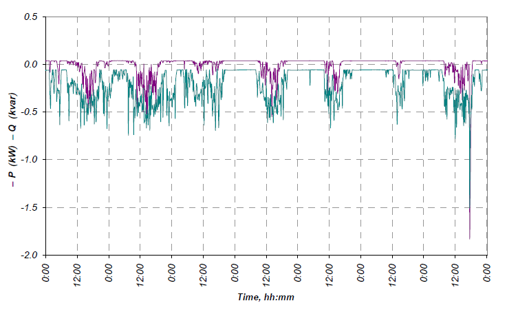
Figure 4 presents the values of voltage THD coefficients. No voltage distortion exceeding the admissible level was observed: THD U ∊ 〈1.88, 3.05〉%.

Figure 5 presents the momentary currents recorded at maximal power generation, i.e. P = Pmin. The current deformation was assessed by obtaining harmonic rms values for n = 2,…,50 and comparing them to the values specified in the relevant standards [4, 6]. The results obtained are presented in Table 2. As can be noted, the plant does not cause higher harmonics of values exceeding the admissible limit level to flow through the connection node of the wind turbine.

Table 2. Comparison of the measured results of higher harmonics with values specified in the standard

The value of THD I for Pmin was THD IPmin = 7.11%. Curves representing the variation of the voltage and current asymmetry coefficients were obtained on the basis of the direct components (U1, I1) and inverse components (U2, I2):

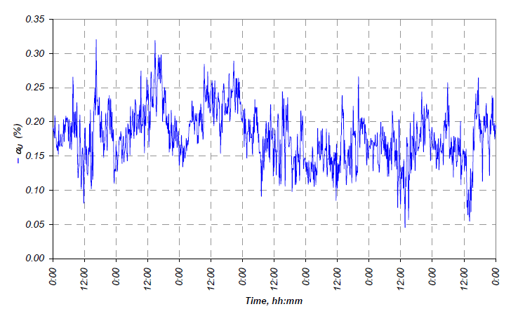
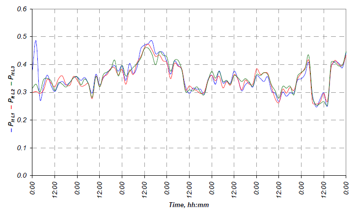
Figure 6 presents the voltage coefficient curve. With the maximal value of the coefficient αUmax = 0.32%, it is significantly smaller than the limit value of 2%. It was also observed that the value of current asymmetry coefficient varies from 1.78% at Pmin to 100% when no power is generated and only the phase L3 is under load due to the power inverter being powered from this circuit. Figure 7 presents the variation of the indices Plt The values of the index Plt are within the interval 0.25 – 0.50, whereas the values of the index Pst are included in the interval 0.07 – 0.67. According to [8], the values of the indices Pst and Plt do not exceed the limit values, as specified in [3]:

The power inverter control system requires continuous supply of active energy E+ (blue), even when it is working at wind speeds below the turbine start-up speed. The amount of active energy consumed during the test week was 5,36 kWh and the amount of reactive energy was EQ (purple) (7.50 kvarh) – Fig. 8. The total net amount of energy supplied to the grid was E+ = 2.08 kWh (green), but is has to be kept in mind that the measurements were taken during summer, and the wind speed attested at that time was not optimum for the operation of the wind turbine.

In order to analyze in detail the plant’s demand for reactive power, additional measurements were carried out, with the consideration of the aggregation time tA = 1 s – Fig. 9. Besides, Figures 10 and 11 present momentary values of currents and voltages, respectively, during the charging of capacitors in the intermediary circuit of the power inverter in the microgeneration plant.


Conclusions
The measurements carried out for the sake of the present study indicate that the operation of the wind turbine does not cause voltage changes exceeding 3%, nor does it cause voltage asymmetry, voltage fluctuations or current harmonics exceeding admissible limit levels. During the charging of the capacitors in the power inverter circuit, impulse currents with momentary values reaching 90 A occurred, which caused additional voltage drop at the grid impedance and contributed to momentary voltage distortion, as shown in Fig. 11. This phenomenon was not however found to interfere with the operation of any devices at the consumer side. Still, it needs to be further scrutinized by the manufacturer of the power inverter with the view to optimizing the control algorithm. Besides, another set of verification measurements should be carried out at wind speeds ensuring generating the rated power of the wind turbine.
REFERENCES
[1] Act on Power Law of 10 April 1997, Journal of Laws of 1997 no 54, item 348, with later amendments (Ustawa z dnia 10 kwietnia 1997 r. Prawo energetyczne, Dz. U. z 1997 r., nr 54, poz. 348 z późn. zm.).
[2] Act on Renewable Energy Sources of 20 February 2015, Journal of Laws of 2015, item 478 (Ustawa z dnia 20 lutego 2015 r. o odnawialnych źródłach energii (Dz. U. z 2015 r., poz. 478).
[3] Connection criteria and technical requirements for microgeneration plants and small-scale generation plants connected to the LV distribution network (Kryteria przyłączania oraz wymagania techniczne dla mikroinstalacji i małych instalacji przyłączanych do sieci dystrybucyjnej niskiego napięcia) TAURON Dystrybucja S.A., Krakow, July 18, 2016
[4] EN 50438 Requirements for micro-generating plants to be connected in parallel with public low-voltage distribution networks
[5] IEC 61000-3-2:2014 Electromagnetic compatibility (EMC) – Part 3-2: Limits – Limits for harmonic current emissions (equipment input current ≤ 16 A per phase).
[6] IEC 61000-4-7:2002+A1:2008 Electromagnetic compatibility (EMC) – Part 4-7: Testing and measurement techniques – General guide on harmonics and interharmonics measurements and instrumentation, for power supply systems and equipment connected thereto.
[7] IEC 61000-4-15:2010 Electromagnetic compatibility (EMC) – Part 4-15: Testing and measurement techniques – Flickermeter Functional and design specifications.
[8] IEC 61000-4-30:2015 Electromagnetic compatibility (EMC) – Part 4-30: Testing and measurement techniques – Power quality measurement methods.
[9] Instructions for Distribution Network Traffic and Exploitation applicable since 01.01.2014, TAURON Dystrybucja S.A. (Instrukcja Ruchu i Eksploatacji Sieci Dystrybucyjnej TAURON Dystrybucja S.A. obowiązująca od dnia 01.01.2014 r.).
[10] The Ministry of Economy ordinance on the detailed conditions of the power system operation, Journal of Laws of 2007, no, 93, item 623 with later amendments (Rozporządzenie Ministra Gospodarki z dnia 4 maja 2007 r. w sprawie szczegółowych warunków funkcjonowania systemu elektroenergetycznego, Dz. U. z 2007 r., nr 93, poz. 623 z późn. zm.).
[11] Turbine MEW-10 catalogue description
[12] Sobierajski M., Rojewski W. ”Conditions for connecting microgeneration plants to the LV grid vs. legal regulations,” (Warunki przyłączania mikrogeneracji do sieci niskiego napięcia w świetle obowiązujących przepisów), Zeszyty Naukowe Wydziału Elektrotechniki i Automatyki Politechniki Gdańskiej, nr 33/2016, pp. 79-82
Authors: dr inż. Andrzej Jąderko, Politechnika Częstochowska, Wydział Elektryczny, Al. Armii Krajowej 17, 42-200 Częstochowa, e-mail: aj@el.pcz.czest.pl
dr inż. Marek Gała, Politechnika Częstochowska, Wydział Elektryczny, Al. Armii Krajowej 17, 42-200 Częstochowa, e-mail:m.gala@el.pcz.czest.pl
Source & Publisher Item Identifier: PRZEGLĄD ELEKTROTECHNICZNY, ISSN 0033-2097, R. 95 NR 1/2019. doi:10.15199/48.2019.01.09
