Published by Ali BAGHERI, Mohsen ALIZADEH, Department of Electrical Engineering, Yadegar -e- Imam Khomeini (RAH) Shahre Rey Branch, Islamic Azad University, Tehran, Iran
Abstract. One of the most important indices of power quality in distribution grids is the harmonic distortion, which can affect the reliability of the micro-grid. On the other hand, the growth of power electronic devices and the emergence of modern industries in distribution grid can led to harmonic distortion emission in the distribution networks. Hence, harmonic analysis of distribution networks has particular importance. Therefore, in the current paper a new method for designing a passive filter is proposed to reduce the harmonics emitted by power electronic devices in a hybrid micro-grid network including nonlinear load, energy storage, wind turbine and solar cell. To do this, a sample harmonic micro-grid is provided in ETAP software which the information needed to design the passive filter is extracted. Then, according to the micro-grid structure and obtained results, the parameters values of the passive filter are determined. Finally, simulation results provided by ETAP software confirm the efficiency of the passive filters as well as the improvement of power quality indices in the micro-grid.
Streszczenie. W artykule zaprezentowano nową metodę projektowania pasywnych filtrów stosowanych do redukcji harmonicznych w sieciach typu micro-grid. Sieć może być obciążona nieliniowym odbiornikiem, zasobnikiem energii I w jej skład może wchodzić turbina wiatrowa oraz panbel fotowoltaiczny. Projektowanie filtrów pasywnych do redukcji harmonicznych w hybrydowej sieci typu micro-grid zawierającej turbinę wiatrową, panel fotowoltaiczny i nieliniowy odbiornik
Keywords: Micro-grid, Power quality, Renewable energy, Passive filters
Słowa kluczowee: micro-grid, redukcja harmonicznych, filtyr pasywny
Introduction
Given the current environmental problems caused by the fossil-fuel power plants all over the world [1], the governments is obliged to devote a specific percent of development for its plants to renewable energies such as wind turbines and solar cells [2]. Accordingly, since these plants usually use an inverter in order to connect to the network as well as existing the nonlinear loads current, the injected power by these units are non-sinusoid [3]. For instance, electric arc furnace and photovoltaic are now producing a high amount of harmonic loads [4], [5]. This should be taken into account more seriously when talking about a micro-grid which is a weak electrical system with low short-circuit power. Because the micro-grid cannot bear mentioned issue in contrast to the large power systems. The power quality indices in power systems are:
1) steady state voltage (under- or over-voltage),
2) steady state voltage unbalance,
3) Harmonics,
4) Voltage fluctuations,
5) short-term interruption (sag or swell),
6) Transient events (impulsive or oscillatory).
However, the most important issue among the mentioned power quality phenomenon for the hybrid micro-grid based on renewable energies is harmonic distortion [6].
Factors and methods of improving power quality in micro-grids have been published in some of the previous studies [7]. However, a few studies have proposed an efficient and practical method to mitigate harmonics at micro-grids. The authors in [8] considered application of passive filters for the power system. However, the mentioned paper is not appropriate for the microgrid. Moreover, in the last decade, authors have proposed to optimize the sizing of harmonic filters using many factors such as cost of filter, power factor, THD, and energy savings [9]. Additionally, although advanced controller such as selective harmonic compensation techniques and the cascaded PR controllers can be used to mitigate the voltage distortion in micro-grids, the main drawback for practical application is complexity of controllers [10]. Harmonic distortions cause serious problems in power micro-grids including lack of proper performance in equipment and also reduced life and efficiency of devices [11]. However, it can be concluded from the aforementioned survey that there have been a few studies published on the harmonic distortion improvement of micro-grid with the presence of high percentage of renewable energies [12].
The major contributions of the current article are:
1- harmonic analysis of a hybrid micro-grid including nonlinear load, energy storage, wind turbine and solar cell,
2- design of a shunt passive filter to comply the requirements of the related standards,
3- the best installation location of passive filter is investigated.
Therefore, the rest of the paper is presented in the following order. Harmonic sources in the micro-grids and the different passive filter are considered in Section 2 and Section 3, respectively. In Section 3, also, harmonic analysis of a hybrid micro-grid is presented. Section 4 considers some scenarios to analysis passive filter application to reduce the harmonics in the micro-grid. In this section, simulation results approve the improvement in power quality parameters related to the harmonics. Finally, discussion and suggestion for future studies are presented.
Harmonics in Micro-grid
The main reason for generating harmonic in the power grids is non-linear loads such as power electronic devices. There are some numerical criteria for showing the amount of harmonics in a signal. THD is one of the most well-known indices for power quality requirement. The permitted limit of current harmonic changes based on the short-circuit level at the point of common coupling (PCC) of the load and maximum load demand, so that the voltage harmonic at distribution grid for PCC must not exceed a maximum value; for instance, as determined in, maximum value of individual harmonic and THD for low voltage levels are 3 and 8%, respectively [13]. On the other hand, the percentage of total harmonic distortion (THD) can be written in two forms; first, as a percentage of the fundamental component (defined by IEEE standard), and second, as a percentage of rms (defined by IEC standard). THD for current and voltage are defined based on Eq. (1)- (2), respectively:
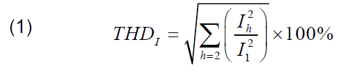
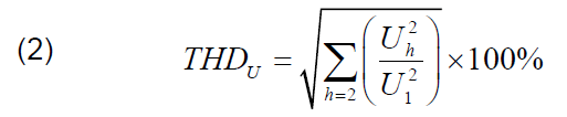
where, I1 and U1 are the first component of non-sinusoid current and voltage, respectively. Also, Ih and Uh are the hth component of non-sinusoid current and voltage, respectively.
Micro-grids
Micro-grid is a small power system which can act either grid connection or island mode. Also, a micro-grid technology makes it possible to use the power system at decentralized control mode. Hybrid AC/DC micro-grids, which AC and DC buses are connected with power electronic converters, are increasingly used in recent years. On one hand, advantages of AC and DC are independently preserved and, on the other hand, simultaneous quick access to AC and DC is possible, which improves the efficiency and power loss with higher economic advantages [14].

Diagram of an AC/DC micro-grid is shown in Figure 1. As it is observed, DC loads, including solar and battery cells, are connected to the DC buses, and Ac loads, including wind and gas turbines are connected to AC bus. These two buses are connected by the power electronic converter.
Solutions to restrain harmonic at the micro-grid
Electric filters are used in a micro-grid to restrain harmonics with a specific frequencies, which are normally composed of three elements including resistor, inductor and capacitator. There are various types of filters such as active filter, passive filter, and hybrid filter.
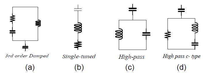
As it was mentioned before, one simple and costeffective way to eliminate harmonics in the micro-grid is to use passive filters. The primary purpose of a passive filter is to reduce the amplitude of one or multiple voltage harmonic components or current in the grid. If this filter is designed to remove a certain frequency component of the micro-grid, one can use a series passive single-tuned passive filter (STPF). Series filter is formed of a capacitor and inductor which provides high impedance path at frequency of the harmonic. However, a parallel passive filter can create shunt path, and also at the same time harmonics are led to the path with low impedance for related frequencies, to prevent harmonic current flowing into the grid. All passive filter types which available in library of ETAP are as following.
1) single-element filter
2) High-pass filter
3) High-pass type C filter
4) 3rd degree damped filter
Single-tuned passive filter
One type of passive filters is the STPF, which has many applications in the power grid. As shown in Figure 2, a series of resistors, inductors, and capacitors can be connected parallel to the grid. Reactance of the capacitor is equal to the inductor for a STPF at a specified frequency (ωn), so the impedance of the filter will be purely resistive as follows:
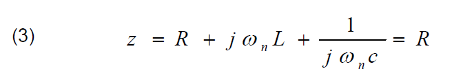
where Z, R, L, and C impedance, resistance, inductance, and capacitance of the filter, respectively. Also, ωn is the resonant frequency of the filter [15], [16].
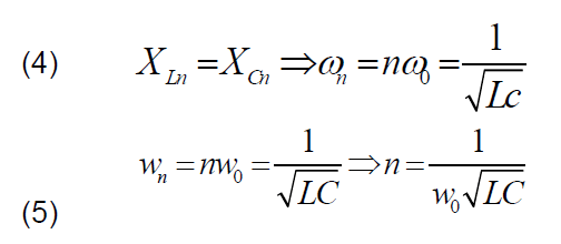
where ω0 is fundamental frequency of the system. XLn and XCn are the inductor and capacitator reactance of the filter in the intensified frequency. Furthermore, n is the harmonic order.
For the optimal performance of the passive filter in the micro-grid, the exact computation of the resistance, inductor, and capacitor are required to operate at a certain harmonic frequency for reducing the corresponding harmonic. In this paper, to eliminate each order of the harmonic in the circuit, a STPF with the equal resonant frequency with the harmonic frequency that is intended to be eliminated. In a single-element passive filter at the desired harmonic frequency, the filter circuit is resonated, resulting in its impedance being very small and guiding the desired harmonic frequency to the ground [17].
Quality factor of Single-element passive filter
Quality factor (QF) of a STPF is a parameter that determines the frequency-impedance characteristics of the filter. Filters with high QF are only designed for elimination of a specific harmonic. On the other hand, if filter has a low QF coefficient, it can weaken the neighbor harmonic components in addition to set frequencies. The QF of STPF is defined as the ratio of the inductor impedance of the filter to the resistance in intensified frequency. However, since the inductor and capacitor reactance of the filter in harmonic frequency are equal, QF can be defined as capacitator impedance to the filter resistance [18], [19]. The QF coefficient is obtained from Eq. (5):

where Q is QF.
It should be noted that STPFs have higher quality coefficient compared to low-pass filters [19].
Injection reactive power by single-tuned passive filter
The most important parameter of a passive filter, which determines the filter size, is the injected reactive power amount at the fundamental frequency. Given the filter impedance feature, it can be concluded that the capacitor impedance of the main frequency will be greater than inductor impedance. That is, the filter can act as a capacitor bank at the fundamental frequency. Generating reactive power of filter at the main frequency are obtained based on Eqs. (7) – (8) [20].
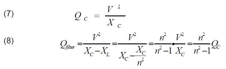
where QC is the reactive capacitor generating power, Qfilter is the filter generating reactive power, and V is voltage of the filter.
Simulation
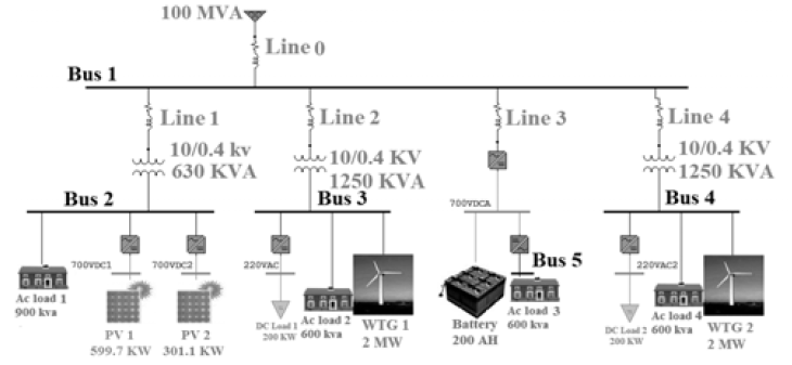
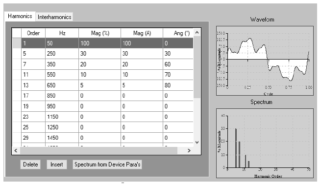
Electrical Power System Analysis (ETAP) is a software for analysis of power system with a perfect graphics connector. This program includes many functions and a comprehensive library. Harmonic analysis at ETAP software is done at two parts; harmonic load and frequency response. This study uses ETAP to analysis a harmonic grid and its frequency response. Figure 4 is the single line diagram of under study micro-grid. This hybrid micro-grid includes AC and DC buses, wind turbine, solar cell, battery, linear loads, and non-linear loads. As shown in Figure 4, three non-linear loads, two solar cell and two wind turbines are considered in buses 2, 3, and 4, respectively. The parameters of these harmonic resources are manually entered into the software, as shown in Figure 5 [21]. Moreover, four scenarios are considered for analysis of harmonic load effect on THD index of micro-grid.
Scenario 1: Using of two solar cells and a non-linear load at bus 2 (measurement at bus 2).
Scenario 2: Using of wind turbine and nonlinear loads at bus 3 with a line length of 1 km for grid connection (measurement at bus 3).
Scenario 3: Using of wind turbine and non-linear load at bus 4 with a line length of 6 km for grid connection (measurement at bus 4).
Scenario 4: Using all the devices as shown in Figure 4.
Results of voltage waveform of the micro-grid at buses 1, 2, 3, and 4 is shown in figure 6.

Table 1. Different buses THD Value of the micro-grid


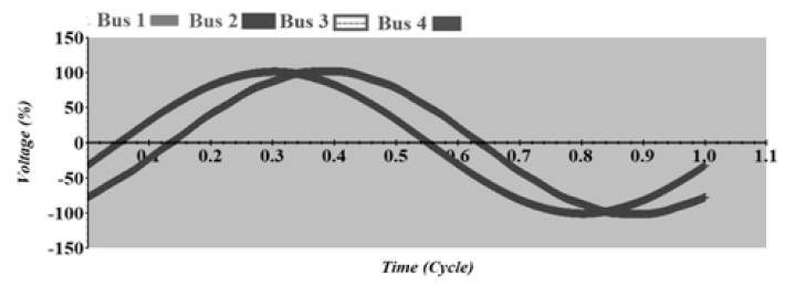
Different buses THD value of the micro-grid are listed in Table 1. As listed in Table 1, bus 2 has the highest THD value due to the presence of solar cell and power electronic device, which leads to changes in waveform as shown in Figure 6. Moreover, as it is obvious, bus 4 has higher harmonic value due to the presence of longer line length comparing to bus 3. It should also be noted that bus DC has been considered ideally in simulations. That is, voltage oscillation is ignored in case of installing a good controller. Now, with designing a STPF, as described in Section 3, it is aimed to reduce the harmonics of different busses within limitations defined in corresponding standards [13]. Designed parameters value of the STPF are shown in Figure 7. Wave form of micro-grids is voltage shown in Figure 8.
Figure 7 shows the designed passive filter editor in ETAP software. As it is shown in Table 1 and figure 6, the voltage quality of micro-grids have been mostly improved. Furthermore, prior to filter installation, THD at buses 1, 2, 3, and 4 are 5.43, 12.76, 7.61 and 8.37, respectively, which have been reduced to 2.54, 0.81, 1.18 and 1.29, respectively, after the filter installation. It should also be noted that installation of filters at micro-grid is costly and economic concerns should be taken into account in studying the filter installation, which is out of the scope of this study.
Table 2. THD values of different buses in the harmonic micro-grid

Conclusion
This paper studies a harmonic micro-grid including wind turbine, solar cell and nonlinear load using ETAP software. Given under study micro-grid, a passive filter was designed and installed for meeting the power quality requirement of the standard. Furthermore, four scenarios were examined to install the filter at micro-grids. The following conclusions can be drawn.
1) Different designs were considered in micro-grid harmonic analysis, in which harmonic increased based on the capacity of solar cell, wind turbine, transformer, cable length and nonlinear load.
2) It was also observed that total harmonic distortion (THD) differed on various buses of the micro-grid using different generators (solar cell or wind turbine).
3) The STPF was designed and used to eliminate the harmonic distortions by the solar cell. The frequency response of the micro-grid approved the improvements.
4) It was observed that the destructive effect of harmonics on voltage appears at the grid which can destruct the insulation of devices.
5) Grid connection line length for the wind turbine can be an essential role in THD, so that by increasing the line length, the THD increases.
Finally, it is suggested to have further studies on economic analysis and also using higher-order filters at distribution grids.
REFERENCES
[1] M. A. Bidgoli, H. A. Mohammadpour, and S. M. T. Bathaee, “Advanced vector control design for DFIM-based hydro power storage for fault ride-through enhancement,” IEEE Trans. Energy Convers., vol. 30, no. 4, pp. 1449–1459, 2015.
[2] P. Mazurek, “Selected aspects of electrical equipment operation with respect to power quality and EMC,” Prz. Elektrotechniczny, vol. 93, no. 1, pp. 21–24, 2017.
[3] N. Eghtedarpour and E. Farjah, “Power control and management in a hybrid AC/DC microgrid,” IEEE Trans. Smart Grid, vol. 5, no. 3, pp. 1494–1505, 2014.
[4] M. Gała and A. J\kaderko, “Assessment of the impact of photovoltaic system on the power quality in the distribution network,” Prz. Elektrotechniczny, vol. 94, 2018.
[5] R. Belaidi and A. Haddouche, “A multi-function grid-connected PV system based on fuzzy logic controller for power quality improvement,” Prz. Elektrotechniczny, vol. 93, 2017.
[6] A. Saim, A. Houari, J. M. Guerrero, A. Djerioui, M. Machmoum, and M. Ait-Ahmed, “Stability Analysis and Robust Damping of Multi-Resonances in Distributed Generation based Islanded Microgrids,” IEEE Trans. Ind. Electron., 2019.
[7] M. Azizi, A. Fatemi, M. Mohamadian, and A. Y. Varjani, “Integrated solution for microgrid power quality assurance,” IEEE Trans. Energy Convers., vol. 27, no. 4, pp. 992–1001, 2012.
[8] J. C. Das, “Passive filters-potentialities and limitations,” IEEE Trans. Ind. Appl., vol. 40, no. 1, pp. 232–241, 2004.
[9] M. M. Elkholy, M. A. El-Hameed, and A. A. El-Fergany, “Harmonic analysis of hybrid renewable microgrids comprising optimal design of passive filters and uncertainties,” Electr. Power Syst. Res., vol. 163, pp. 491–501, 2018.
[10] S. Yang, P. Wang, Y. Tang, and L. Zhang, “Explicit phase lead filter design in repetitive control for voltage harmonic mitigation of VSI-based islanded microgrids,” IEEE Trans. Ind. Electron., vol. 64, no. 1, pp. 817–826, 2017.
[11] J. Arrillaga and N. R. Watson, Power system harmonics. John Wiley & Sons, 2004.
[12] Y. Liu, H. A. Mantooth, J. C. Balda, and C. Farnell, “A Variable Inductor BasedLCLFilter for Large-Scale Microgrid Application,” IEEE Trans. Power Electron., vol. 33, no. 9, pp. 7338–7348, 2018.
[13] R. Langella, A. Testa, and E. Alii, “Ieee recommended practice and requirements for harmonic control in electric power systems,” 2014.
[14] X. Wu, L. Chen, C. Shen, Y. Xu, J. He, and C. Fang, “Distributed optimal operation of hierarchically controlled microgrids,” IET Gener. Transm. Distrib., vol. 12, no. 18, pp. 4142–4152, 2018.
[15] S. P. Diwan, H. P. Inamdar, and A. P. Vaidya, “Simulation Studies of Shunt Passive Harmonic Filters: Six Pulse Rectifier Load-Power Factor Improvement and Harmonic Control,” ACEEE Int. J. Electr. Power Eng., vol. 2, no. 1, pp. 1–6, 2011.
[16] C. L. Anooja and N. Leena, “Passive Filter For Harmonic Mitigation Of Power Diode Rectifier And SCR Rectifier Fed Loads,” Int. J. Sci. Eng. Res., vol. 4, no. 6, 2013.
[17] O. Anaya-Lara and E. Acha, “Modeling and analysis of custom power systems by PSCAD/EMTDC,” IEEE Trans. power Deliv., vol. 17, no. 1, pp. 266–272, 2002.
[18] K. K. Srivastava, S. Shakil, and A. V. Pandey, “Harmonics & its mitigation technique by passive shunt filter,” Int. J. Soft Comput. Eng. ISSN, pp. 2231–2307, 2013.
[19] Y.-S. Cho and H. Cha, “Single-tuned passive harmonic filter design considering variances of tuning and quality factor,” J. Int. Counc. Electr. Eng., vol. 1, no. 1, pp. 7–13, 2011.
[20] T. M. Bloom and D. J. Carnovale, “Harmonic convergence,” IEEE Ind. Appl. Mag., vol. 13, no. 1, pp. 21–27, 2007.
[21] X. Chen and G. Zhang, “Harmonic analysis of AC-DC hybrid microgrid based on ETAP,” in 2016 IEEE 8th International Power Electronics and Motion Control Conference (IPEMCECCE Asia), 2016, pp. 685–689.
Authors: Mohsen Alizadeh Bidgoli as corresponding author (Ph.D.), Email: m.alizadeh.b@gmail.com, Ali Bagheri (M.Sc.) Email: bagheriiali1374@gmail.com, Department of Electrical Engineering, Yadegar -e- Imam Khomeini (RAH) Shahre Rey Branch, Islamic Azad University, Tehran, Iran
*Corresponding author: M.Alizadeh Bidgoli
Source & Publisher Item Identifier: PRZEGLĄD ELEKTROTECHNICZNY, ISSN 0033-2097, R. 95 NR 12/2019. doi:10.15199/48.2019.12.02
