Published by Jiri JANSA, Petr MOLDRIK, Daniel MINARIK, VSB – Technical University of Ostrava
Abstract. This paper deals with the utilisation of firedamp for combined heat and electric power generation. The firedamp is gained from hard-coal mines and can be combusted in a co-generation units with gas-engine. This process involves more efficient utilisation of firedamp. The measurement results obtained on selected co-generation units are described in this paper. As far as the electric power supplied into the grid from cogeneration unit´s are concerned, these shall be considered with respect to the qualitative parameters, which should comply with stipulations of the CSN EN 50160 standard. The main advantages and disadvantages of co-generation units producing heat for hard-coal mine and electric power for export to the grid are described in the end of this paper.
Streszczenie. Opisano możliwość wykorzystania gazu kopalnianego do ogrzewania i wytwarzania energii. Gaz może być wykorzystany w kogeneratorze z silnikiem gazowym. Opisano wybrane systemy wytwarzania energii. (Jakość energii elektrycznej dołączanej do sieci przy wykorzystaniu dodatkowej generatora wykorzystującego gaz kopalniany)
Keywords: Firedamp; Quality of electric power; Combined heat and power generation; Hard-coal minet.
Słowa kluczowe: jakopść energy, gaz kopalniany.
Introduction
Issues concerning utilisation of renewable energy sources (RES) and combined production of electric power and heat belong to commonly discussed topics. Apart from RES represented by solar energy, biomass, wind or geothermal power, the interest is also shifting towards secondary energy resources including firedamp as well. Less awareness of this medium is related to its occurrence at local deposits mostly of bituminous coal. Coal deposits are accompanied by deposits of the firedamp. This firedamp develop from the original biological matter subject to geological processes during its carbonisation. Opening of coal deposits when mining then releases the firedamp, which penetrate the extracted mine space and surfaces. Composition of firedamp depends on many geological aspects as well as conditions associated with coal mining or situation of mining works, where the physical extraction has finished. Firedamp comprises methane, carbon dioxide, nitrogen and heavy hydrocarbons. In this case (at selected hard-coal mine), the methane content equals to approximately 65 % and the gas calorific value is approx. 23 MJ/m3. [1]
In technological processes performed in underground workings, methane is released which, unless taken in by the de-methaning systems, is discharged to the atmosphere by the ventilation systems of the mines. The ventilation systems are the primary and main methane emission source from coal mines. Methane, in this case called „residual gas“, is also contained in the coal extracted to the surface and released during the extraction processes. Some methane is also contained in the bedrock extracted to the surface with coal and gets released during bedrock disposal. This is the third source of methane emission. In many cases, firedamp is actively removed from the coalfield by various methods, normally described collectively as methane drainage. This is primarily for reasons of safety. As an example, in the Czech Republic in 2012, 18 % of the firedamp released by deep mining was vented from methane drainage systems, 16 % was captured and used as fuel, 57 % was emitted with ventilation air and about 9 % was removed in the mined coal. [2]
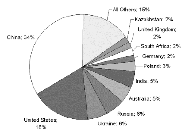
Coal mine methane (CMM) emissions are globally distributed among the world’s key coal-producing countries. Methane is a well-mixed gas in the atmosphere and emissions reductions anywhere in the world are important to reducing the total global burden of CMM emissions. The largest emitters are countries with the highest production of highrank underground coal. Currently, the top two producers of coal and emitters of CMM are China followed by the United States. Other large coal producers include Russia, Australia, Ukraine and India. The percent contribution for each country´s estimated CMM emissions are illustrated in Fig. 1.
The current drop in global emissions is associated with a decline in coal production in many countries, in addition to a restructuring of the coal industries in countries such as China, Russia and other Easter European coal-producing countries. With international studies showing that about 30 % to 40 % of all coal mines produce firedamp that could be used to fuel gas-engines for power generation, clearly the energy benefits could be enormous. However, not all firedamps are the same and these differences have implications for its utilisation.
Coal mine methane (CMM) may also be used as a fuel for power generation. Mines can use electricity generated from recovered methane to meet their own onsite electricity requirements, and they can sell electricity generated in excess of their onsite needs to utilities. Outside of the U.S., power generation is often the preferred option for using CMM. Power generation projects using CMM are operating at coal mines in several countries, including China, Australia, United Kingdom, Germany and Czech Republic. The production of electric power using the secondary energy sources gained vital legislative support in the Czech Republic (Act No. 180/2005 Coll.).
I. Utilisation of Firedamp at Selected Hard-coal Mine
The selected hard-coal mine in the vicinity of Ostrava city in the Czech Republic makes use of air pumps to drain the firedamp by means of forced extraction through boreholes in the rock material. Degasifying station on the surface then guides the firedamp into two co-generation units to be combusted for generation of electric power and heat. Electric power is supplied into the grid and heat is used for heating of bath water in showers, preparation of domestic hot water and heating in operation facilities.
Co-generation
The term “co-generation” defines simultaneous production of electric power and heat. The process of conversion of energy gained from fuels begins with the utilisation of high-potential heat energy to perform the work (production of electric power) with the subsequent use of the working substance of lower temperature used to cover the needs for heat. The fuel used within the co-generation unit can comprise of firedamp extracted from hard-coal mine. The essential technological feature of every co-generation unit is the combustion turbine or the combustion engine driving the power generator. [4]
Co-generation Unit Measured
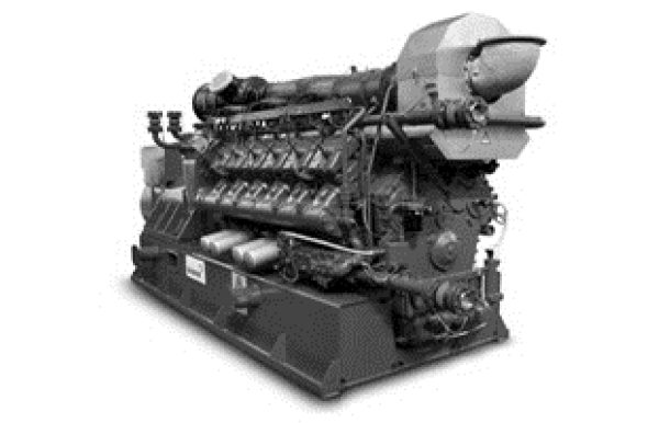
The measurement and assessment of quality of the electric power supplied was performed at the two cogeneration units (CU) labelled as TEDOM Quanto C2000 SP, installed in the year 2012. Both CUs are based on the gas combustion engine model Deutz TCG 2020 V16 (see Fig. 2) with the max. power output of 1558 kW to drive the lowvoltage (400 V) synchronous electric power generator Marelli M8B 500 SD4. The said mechanism is suspended from the basis frame. The heat generated by the combustion engine and drawn from exhaust gases is run through the system of exchangers to the access flanges. The lost heat developed within the acoustic container of the CU (emitted from hot parts) is discharged with the ventilation air. The ventilation is provided by means of ceiling extractor fan. The acoustic air channels and exhaust silencers ensure the low level of noise from the CU.
The interior contains an integrated distribution box ensuring the delivery of output as well as all the operation and control functions. The brain of the CU comprises of the control system, which enables for full control of its operation. The nominal power output of this CU is 1558 kW, the max. heating capacity is 1583 kW, the max. rate of consumption of the firedamp is equal to 755.2 m3/h and the total efficiency of the co-generation unit equals to 85.7 % (fuel utilisation efficiency). [5]
II. Quality of Electric Power Supplied by Co-generation Units
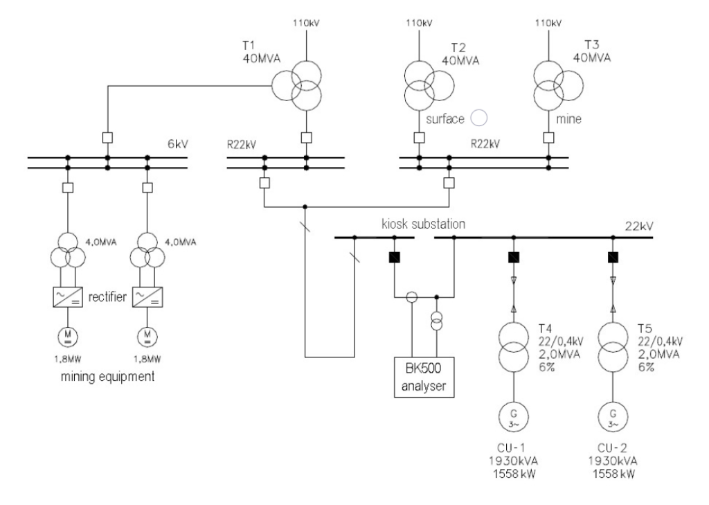
The following includes the assessment of selected parameters of electric power, which is supplied into the local 22 kV grid from two co-generation units (CU-1 and CU-2) via the kiosk substation (see Fig. 2). The basics for benchmarking of electric power parameters are stipulated by the CSN EN 50160 standard, which deals with the quality of electric power. [6]
Description of the Measuring Method
The measurements were conducted using the BK500 analyser made by ELCOM Inc., connected to the kiosk substation 22 kV (see Fig. 3). Both co-generation units are connected to this substation via two transformers 0.4/22 kV (2 MVA). Current sensors used are the split-core current transformer type Chauvin Arnoux (10-100 A). The hardware of BK500 analyser comprises the heavy duty PC type DEWETRON 2000 made from premium standard PC components integrated in a durable portable case. Monitoring of voltage signal and current from the grid are conducted by means of measuring cards made by the National Instruments company.
The analyser performed measurements and evaluation of the following values: voltage, current, active and reactive power, phase factor, frequency, flicker (a visual perception induced by a light stimulus the brightness of which fluctuates over time), harmonic voltage of higher levels (higher harmonic voltage) and the harmonic distortion factor.
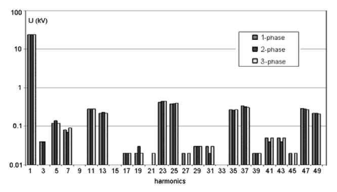
The measurement was performed within the period from 14th February till 18th February 2013. The said values were determined in every phase (L1, L2, L3). Following Fig. 4, Fig. 5, Fig. 6, Fig. 7, Fig. 8 and Fig. 9 show the selected values development in time. Fig. 10 show the spectrum of voltage harmonics.

Results of measurement
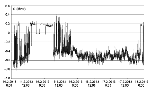
• Active and reactive power supplied by co-generation units (see Fig. 4 and Fig. 5): That is a sum of power output from both units. One of the units supplied the grid will active power of approx. 1.5 MW, both units then supplied approx. 3 MW. The reactive power ranges within the interval from approx. 0.5 Mvar (inductive nature) to 0.8 Mvar (capacity nature). That corresponds with power factor of 0.9 to 1.0, which dropped to the value of 0.75 at the time both cogeneration units were deactivated.
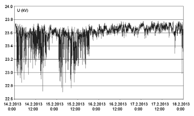
• Voltage in the kiosk substation (see Fig. 6): From the very beginning of the measuring process up until approx. 6.00 p.m. on 15th February, the voltage fluctuated within the range of 1 kV, which corresponds with 5 % of the nominal voltage. Further drops in voltage were substantially weaker afterwards (approx. 0.2 kV). The characteristic of voltage fluctuation, i.e. magnitude and frequency of voltage changes, is not dependant on operation of co-generation units. Such fluctuation of voltage is caused by other devices connected to the joint 22kV grid.
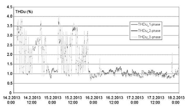
• Total harmonic distortion of voltage (see Fig. 7): Up until 6 p.m. on 15th February, the voltage distortion had been very high (4.5 to 6.5 % at maximum). However, that had not been due to operation of co-generation units, which have not visible impact on voltage distortion. As of 6 p.m. on 15th February, the voltage distortion fell to 1.5 %.
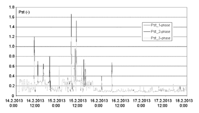
• The short-term flicker perception rate (see Fig. 8): This value is evidently not dependent on operation of cogeneration units, yet it is rather affected by mining equipment and other loads within the 22 kV grid. The percentile for 95 % is approx. 0.32. Therefore this value is low and conditions stipulated by the standard have been met. The permitted value of (1.0) was exceeded in a shortterm due to switching operations within the grid only.
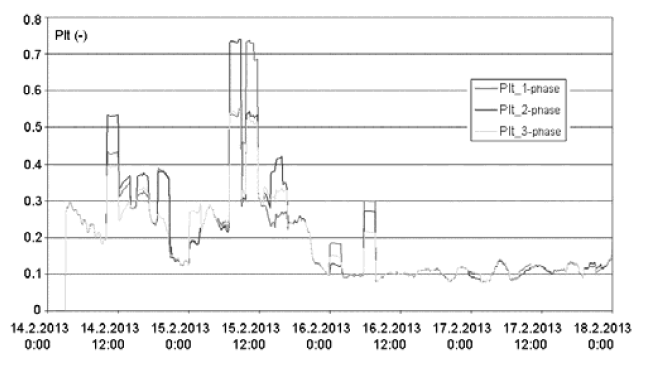
• The long-term flicker perception rate (see Fig. 9): Conditions set forth in the standard have been met.
• Spectrum of voltage harmonics (see Fig. 10): High values of 11th, 13th, 23rd, 25th, 35th, 37th, 47th and 49th voltage harmonic (during the measurement period till approx. 6 p.m. on 15th February) are typical for operation of rectifiers with a twelve-pulse connection. That is due to operation of mining equipment operating within the hard-coal mine. Conditions stipulated by the CSN EN 501060 standard were not met for 23rd and 25th voltage harmonics only, where the permitted threshold values were exceeded (1.72 % > 1.5 % and 1.63 % > 1.5 % respectively).
• Other parameters as frequency, voltage magnitude and voltage asymmetry complied with conditions defined by the CSN EN 501060 standard.
Conclusion
The main part of this paper dealt with the evaluation of the quality of electric power supplied into the 22 kV grid by two co-generation units with firedamp combustion. The assessments conducted did not concern the production of heat or its parameters. The five-day measurement focused on the magnitude of voltage, the higher harmonics, the total harmonic distortion, the flicker perception rate, the voltage frequency and the asymmetry of three-phase voltage. Cogeneration units subject to measurement do not have any negative impact on qualitative parameters within the 22 kV grid. However, excitation of synchronous generators on both co-generation units could use certain adjustments to make them work with power factor of 1.0 to prevent their excessive or insufficient compensation.
Conditions stipulated by the CSN EN 501060 standard were not met during measurement. The permitted threshold values were exceeded at 23rd and 25th voltage harmonics due to operation of mining equipment in the said hard-coal mine. This mining equipment is controlled by siliconcontrolled rectifiers, which is causes higher values of voltage harmonics of higher level in the mine power main, which is connected to the 22 kV grid. Operation of mining equipment also causes voltage changes in the grid (5 % out of 22 kV). Yet the frequency of such changes is not that high to cause flicker problems. Both the short- and long-term flicker perception rates comply with conditions stipulated in the standard.
With regards to the minimum costs associated with extraction of firedamp, this is a very interesting energy resource. There are currently further co-generation unit projects being prepared for the region of Ostrava city (Czech Republic), including exploration of suitable deposits of firedamp. Yet the future perspectives shall also consider gradual decrease of output from existing boreholes and the need to search for new deposits in spite of the higher costs associated with it.
The main advantages of co-generation unit with gas engine generators producing heat and electric power for hard-coal mine use or export to the grid are: Proven technology; Waste heat recovery for heating mine buildings, miner baths, and shaft heating and cooling. The main disadvantages are: Interruptible and variable output; Regular maintenance requires commitment of mine operator; High capital costs.
ACKNOWLEDGEMENT
This paper was supported by the project ENET – Research and Development for Innovations Operational Programme No. CZ.1.05/2.1.00/03.0069, by the project New creative teams in priorities of scientific research, reg. No. CZ.1.07/2.3.00/30.0055, Operational Programme Education for Competitiveness, co-financed by the European Social Fund and the state budget of the Czech Republicby, by the Czech Science Foundation: project No. GAČR102/09/1842 and by grant of SGS No. SP2013/137 (VŠB – TU Ostrava).
REFERENCES
[1] Prokop, P., Důlni degazace. VŠB – Technical University of Ostrava, Issue: 1, Page(s): 1-112, Ostrava, 2008.
[2] Ivancova, P., Využití důlních plynů na území Ostravskokarvinského revíru. VŠB – Technical University of
Ostrava, Thesis, Issue: 1, Page(s): 1-46, Ostrava, 2012.
[3] Karacan, C.O., Ruiz, F.A., Cote, M., Phipps, S., Coal mine methane: A review of capture and utilization practices with benefits to mining safety and to greenhouse gas reduction. International Journal of Coal Geology, Vol. 86, Page(s): 121-156, 2011.
[4] Dvorsky, E., Hejtmankova, P., Kombinovaná výroba elektrické a tepelné energie. BEN – technical literature, Issue: 1, Page(s): 1- 287, Praha, 2006.
[5] TEDOM co-generation units: Production schedule. [online]: http: //kogenerace.tedom.cz.
[6] ČSN EN 50160 standard: Voltage characteristics of electric power supplied by public distribution network. Czech Standards Institute, Praha, 2000.
Authors: Ing. Jiri Jansa, Ing. Petr Moldrik, Ph.D., Ing. Daniel Minarik, Ph.D., Technical University of Ostrava, Centre of Energy Units for Utilization of non Traditional Energy Sources – ENET, ul. 17. listopadu 15, 708 33 Ostrava – Poruba, Czech Republic, E-mail: jiri.jansa.st@vsb.cz, petr.moldrik@vsb.cz, daniel.minarik@vsb.cz;
Source & Publisher Item Identifier: PRZEGLĄD ELEKTROTECHNICZNY, ISSN 0033-2097, R. 89 NR 11/2013
