Published by Dirk Danninger IEEE Member Schweitzer Engineering Laboratories, Inc. 2350 NE Hopkins Court Pullman, WA 99163, USA
Scott Manson Senior Member, IEEE Schweitzer Engineering Laboratories, Inc. 2350 NE Hopkins Court Pullman, WA 99163, USA
Fernando Calero IEEE Member Schweitzer Engineering Laboratories, Inc. 2350 NE Hopkins Court Pullman, WA 99163, USA
Ceeman Vellaithurai Senior Member, IEEE Schweitzer Engineering Laboratories, Inc. 2350 NE Hopkins Court Pullman, WA 99163, USA
Abstract—In this paper, we share the experiences of designing, installing, and commissioning grounding and ground fault protection systems for three different low-voltage and medium-voltage power systems. The first project is a low-voltage service entrance with a standby generator. The second is a large peak shaving battery and a photovoltaic (PV) power plant that must seamlessly island and reconnect to the transmission grid without loss of power to customers. The third is a transportable microgrid with a grid forming with droop battery inverter and synchronous condenser with a flywheel. Complicating these designs are the great diversity in 480 V power system designs, the limitations of inverters, and the need to comply with National Electric Code (NEC). NEC compliance and good engineering practices are explained. The logic behind each design is shared, and a checklist is provided to guide others in proper design practices. The solutions shared are shown to be simple, easily maintained, reliable, NEC compliant, fully monitored, and ready for the rapidly changing power system of the future.
Index Terms—Ground fault protection, microgrid, service entrance, transportable microgrid, and renewable power plant.
I. INTRODUCTION
With the proliferation of distributed energy resources (DERs) found in microgrids and the large variety of vendors with varying protection philosophies, the interconnection of these resources to utility grids while maintaining ground fault detection and isolation is becoming increasingly complex. The complexity arises in part because, in industrial and commercial low-voltage distribution, the ground conductor cannot carry any current during normal operation to ensure the local and equipment grounds are at the same potential for personnel safety. In a three-wire system, this is easily achievable, since no neutral conductor exists. However, in a four-wire system, loads are connected as line-to-line and line-to-neutral. Thus, the neutral and ground must be isolated throughout the distribution and bonded to ground at only one point, typically at the service entrance. When more than one source has the neutral grounded, additional measures must be taken to detect and trip upon current flow on the multipoint grounded systems. Moreover, many microgrid projects are sponsored and funded by utility entities that are generally exempt from the National Electric Code (NEC) requirements, which may apply at DER sites.
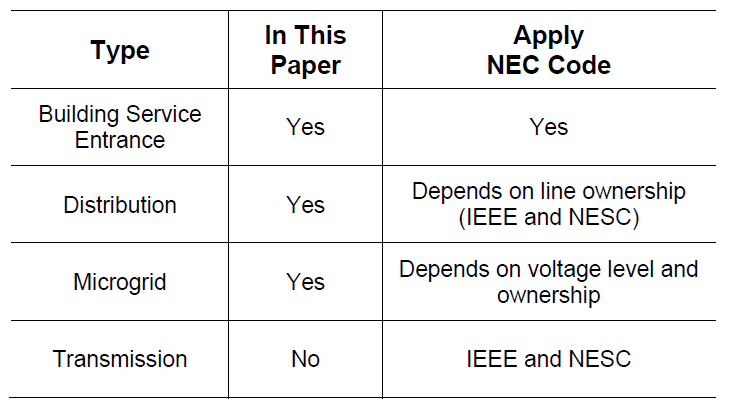
In this paper, we discuss several ground fault detection schemes and provide an example for each, as listed in TABLE I.
TABLE I. POWER SOURCE TYPES AND APPLICABLE CODES
II. LOW-VOLTAGE BUILDING SERVICE ENTRANCE
A. Background
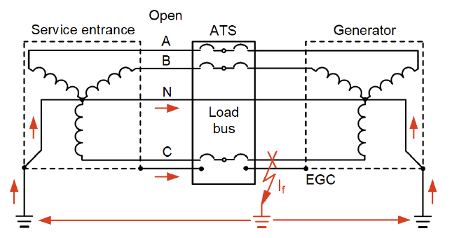
Fig. 1 illustrates a typical indoor service entrance with both utility and generator sources and branch distribution breakers.
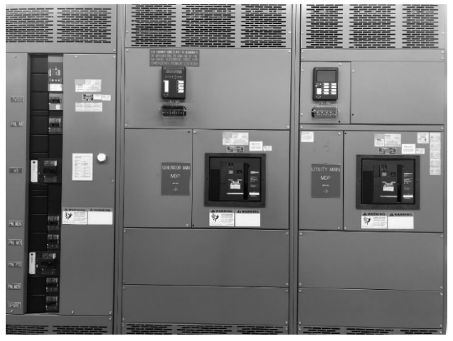
This type of service entrance is used to provide emergency backup power to a critical facility. Each source may or may not be grounded at either the source itself or at the service entrance. The multiple-point grounding possibilities with this type of equipment presents challenges for proper ground fault detection when either one of the sources are supplying the load or if both are supplying the load (paralleled operation).
The NEC Article 250 covers the general requirements for grounding and bonding systems [1]. The NEC contains many additional articles that are equipment-specific requirements (e.g., cables, cords, motors, and switchgear) and various types of grounding (e.g., solid, low-resistance, and high-resistance).
A grounded system has at least one conductor or point (usually the neutral point of a transformer or generator winding), which is intentionally grounded, either solidly or through an impedance, as discussed in Section 3.1 of [2].
System grounding is meant to control the voltage with respect to the earth (ground) within predictable limits and provide a flow of current that allows the detection of an unwanted connection between system conductors and ground so that the unwanted connection can be purposefully removed, as discussed in Section 1.3 of [2].
Grounding and bonding ensure that voltage potentials between conductive parts of a system are minimized during normal operation and during faults to protect personnel from electric shock.
For low-voltage building service entrances (277/480 V), the NEC Article 230.95 requires ground fault protection with 1,000 A or larger services, and must detect and trip for faults below 1,200 A. It is required that a fault at or above 3,000 A is cleared within one second. These NEC requirements are for equipment protection, not personnel protection. This paper, therefore, focuses on equipment protection.
Similarly, it is important to draw a distinction between system grounding and equipment grounding. A system may be grounded or ungrounded. In an ungrounded system, none of the transformer secondary conductors are intentionally connected to the ground. In a grounded system, the neutral is the most common conductor bonded to the grounding electrode. There are some systems where other grounding schemes are deployed, such as a corner delta or center tap grounding, which is not within scope of this paper. System grounding is the grounding of the power system. Equipment grounding refers to the installation of the equipment grounding conductor (EGC) to provide a low-impedance path for ground fault current to flow back to the source. Absence of a low-impedance path can leave parts of the equipment energized that could lead to shocks or flashovers.
Systems employing a single service at the service entrance provide the required ground fault protection by use of circuit breakers (CBs) that, in addition to overcurrent protection, also have ground fault protection typically denoted by a G in a breaker function marking. For example, long, short, instantaneous, and ground (LSIG) breaker trip functions are typically denoted as an LSIG breaker. Service entrances can also be used as a microgrid point of common coupling (PCC) and are commonly protected and controlled by programmable protective relays (PPR), which have advanced features that go far beyond LSIG.
A microgrid, by definition, may have many DERs, and a service to a building may be from more than a single source. For example, an automatic transfer switch (ATS) can supply a building by two different sources. To limit the building’s power outages during microgrid operations, it may be beneficial to transfer the building load to or from either source without interrupting the load. This is a closed-transition transfer. Moreover, it may also be beneficial to maintain both sources connected in parallel to help support the microgrid (e.g., using a building emergency generator to serve both the building and simultaneously participate in microgrid functions, like peak load shaving).
Operating multiple sources in parallel with the PCC is a challenge if each source is grounded and if a ground fault occurs within the building’s electrical distribution, as the fault current has multiple paths to return to its source and may not trip the service breakers; the ground fault detection becomes desensitized in this configuration. Additionally, in four-wire systems, the common neutral between the two sources has a unique set of challenges for ground fault sensing since this common neutral presents another path for ground current to flow [3].
B. Detecting and Protecting
Detecting a ground fault on multiple three-wire sources, in principle, is simple—add all the current transformer (CT) secondary currents together, and if they are greater than zero, there is a ground fault, as illustrated in Fig. 2.

A single source to a load (right side of Fig. 2) and a detection system is presented. The goal of the detection and protection system is to protect the load; the protected zone is the load shown in Fig. 2. For a three-wire system, a phase-to-ground fault can be readily detected by the PPR as the sum of the three-phase currents, Ig is the ground fault current divided by the CT ratio. Summing the three-phase currents works well for three-wire systems where the load is only connected between the phases. However, many low-voltage commercial and industrial systems use both line-to-line and line-to-neutral connected loads and are four-wire systems (e.g., 120/208 V and 277/480 V), as illustrated in Fig. 3.
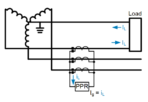
Fig. 3 illustrates a four-wire system with a connected load between a phase and the neutral. The relay now measures a current IL in proportion to the load in the neutral—that is, the relay technique of summing the three-phase currents includes the load and fault currents. Any elements based on Ig in Fig. 3 must be set above the largest load imbalance. This requirement can create coordination challenges on large single-phase cold load pickups and inrush conditions. To remedy this problem, adding another CT on the neutral to the summation network cancels out the phase current.
Fig. 4 illustrates a differential current scheme; the ground current, Ig, is represented as the difference of current on all current carrying conductors, including the neutral. The relay can supervise Ig and trip when necessary without any dependency of phase and neutral loads.

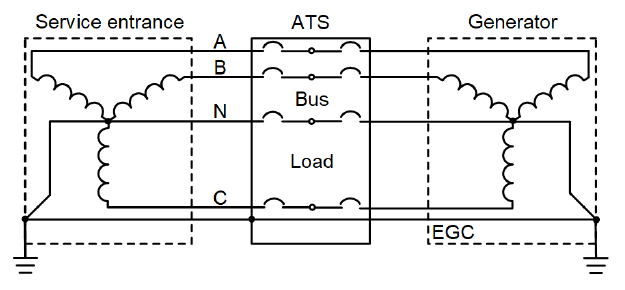
The NEC classifies grounding systems as either nonseparately derived systems (NSDSs) (see Fig. 5) or separately derived systems (SDSs) (see Fig. 7).
In a system with a utility service and backup generator, the ATS or CB may be three- or four-pole in design. In a three-pole ATS or CB, the neutral conductor is not switched. The system retains a direct electrical connection between the neutral of the service and the generator neutral through the neutral bus in the ATS. This type of system is considered an NSDS. An EGC must run from the generator to the ATS to provide a low-impedance path for ground fault current. The NEC requires that the system is grounded at only one location for an NSDS, usually through a bonding jumper at the service utility transformer in such a system. This requirement is to prevent the existence of parallel paths during ground faults. The issue when multiple grounds exist in such a system is represented in Fig. 6. The fault current splits across the neutral and EGC. Because part of the fault current returns through the neutral conductor, the ground fault detection using a scheme similar to Fig. 4 would be desensitized and potentially defeated (relaying dependability), depending on the location of the fault.
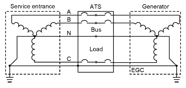
In a four-pole ATS, the neutral conductor is switched. In this case, direct electrical connection between the service and generator is severed during ATS operation. Such a system is considered an SDS, and a separate grounding electrode conductor and grounding electrode must be installed for the SDS generator to maintain proper grounding when load is supplied by the generator. Fig. 7 shows a representation of an SDS.
Ground fault protection on an NSDS can be tricky when multiple standby generators or other sources are involved. Using the scheme in Fig. 4 would not work because the fault current supplied by the generator would return on the neutral, causing the value to remain at zero. The fault current must return to the source through the neutral; therefore, a residual calculation of just the phase currents or a direct measurement of the neutral current is suitable in this instance. However, a study should be completed to carefully examine the circulating currents between parallel generators and load imbalance that could contribute to currents in the neutral conductor. Even generators of the same type and manufacturer commonly have circulating currents due to winding and impedance asymmetries similar to paralleled transformers. In this case, the pickup should be set above the maximum normally expected current in the neutral conductor and coordinated with other feeder protection. Additionally, the service entrance ground fault protection operation needs to be supervised based on breaker or ATS status so that a false indication on the nonload supplying breaker does not occur when the system is operating from the alternate source.
The use of a three- and four-pole ATS complicates ground fault detection through the presence of parallel paths when multiple grounds are provided and the sources are paralleled. When more than one source is supplying a load, such as a paralleled ATS to a utility and generator or a main-tie-main supplying a service entrance, a scheme similar to Fig. 4 can be employed but with some modifications to provide ground fault protection. One common scheme is called a Modified Differential Ground Fault (MDGF) scheme, as shown in Fig. 8 [3] [4] [5].
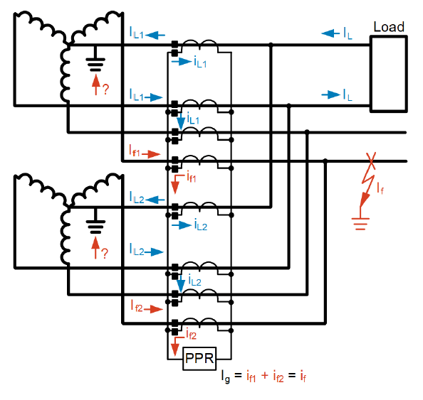
Fig. 8 illustrates the MDGF scheme for multiple sources. Load currents on either the phases or neutral are properly canceled, and only the current associated with a ground fault is sensed by the PPR. The ground fault current is the sum of the individual source contributions, which may not be equal due to different impedances. In this configuration, it is fortunate that different fault current contributions are not relevant.
The diagrams presented thus far have illustrated the use of CTs in a summation configuration. A core-balanced CT is typically neither practical nor economical because of the physical bus size and routing configurations found in these applications. Using dedicated CTs solely for ground fault differential measurements and requiring another set of CTs for traditional phase current monitoring and protection is not economical. A CT arrangement to serve both purposes is needed.
Fig. 9 illustrates the complete solution for a protection system, which includes ground fault protection. In this arrangement, the eight CTs provide signals for individual phase currents for traditional protection, and the summation of the current signals routed through the relay IN provide for the differential ground fault protection.
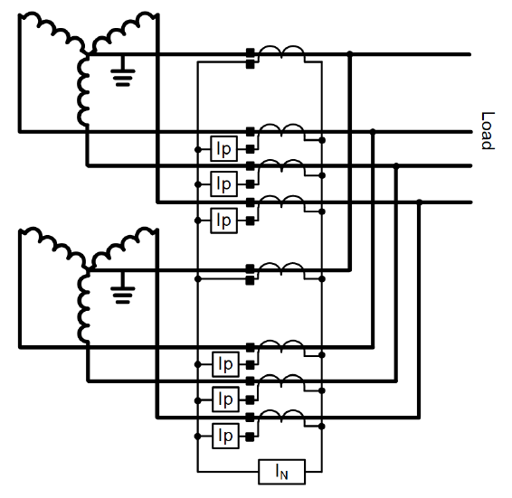
The arrangement requires no additional CTs or relays than necessary for individual service feeder protection, which makes this solution economical and simple. A PPR with seven current inputs economically satisfies the relaying requirements in this arrangement [6].
It should be noted that this differential scheme is generally applicable only to solidly grounded systems because the differential currents (IN) measured by the relay for ground faults depend on the ratios of the phase and neutral CTs. For proper current summation, as presented in Fig. 9, the ratios, class, and manufacturer of all CTs in Fig. 9 must be matched. On resistance-grounded systems, the neutral is connected to the earth ground by means of an impedance, thereby, limiting the let-through primary current to typically 5–20 A. A CT ratio (CTR) on the neutral of a resistance-grounded system is, therefore, much lower than the phase CTR, due to the low let-through currents rendering the method in Fig. 9 ineffective. Since the differential scheme presented here would not be sufficiently sensitive to detect ground faults on impedance grounded systems, an alternative scheme must be employed that digitally sums all the phase and neutral primary currents, which is not in the scope of this paper.
III. SERVICE ENTRANCE EXAMPLE
The solution of Fig. 9 has been employed at several facilities. In the following example, a dual-fed indoor service entrance of Fig. 1 is presented. The service entrance is a 2,500 A, 277/480 V service with a 600-kW backup diesel generator. In Fig. 10, there are two protection relays, one for each service (utility and generator).
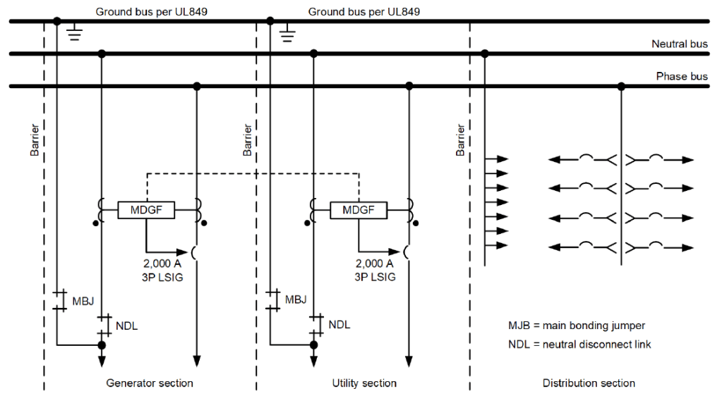
Fig. 10 illustrates the single line of the dual-fed service entrance shown in Fig. 1. In this formation, the MDGF units sum the currents in a similar manner, as presented in Fig. 8. The summed current is routed through the LSIG breaker’s external Ig sensor terminals, thereby, allowing the breaker’s trip unit to monitor the ground fault current magnitude and trip when the settings are exceeded, which is similar to the PPR in Fig. 8.
The advantage of using a PPR (as illustrated in Fig. 9) and eliminating the MDGF hardware and associated CTs is a simplified protection system that can accomplish phase, neutral, and ground current protection, in addition to many other protection elements available in many modern digital relays. With the logic programming capability of a PPR, the relay can also detect power supply interruptions on either source, properly sequence breakers to maintain the load from either source, as well as ensure bus synchronism in a makebefore-break automatic transfer scheme. In addition, the PPR has oscillography, Sequence of Events (SOE) recording, and several communications protocols.
This simple yet effective solution provides a robust relay-based automatic transfer scheme and is a significant building block for microgrids providing the end user with seamless transfer between utility and generator power or interconnection of multiple microgrids.
IV. RENEWABLE POWER PLANT EXAMPLE
A. Background
Distribution substations with DER generation have been proposed [7]. Photovoltaic (PV) generation and a controllable battery energy storage system (BESS) linked to a distribution substation can provide several benefits, including resilience and peak load shaving strategies.
Fig. 11 illustrates this concept. The distribution substation is traditionally connected to the BEPS (Bulk Electric Power System) through the PCC breaker. This is the normal state of the system; however, PV and BESS generation can be dispatched according to the need of the distribution system.
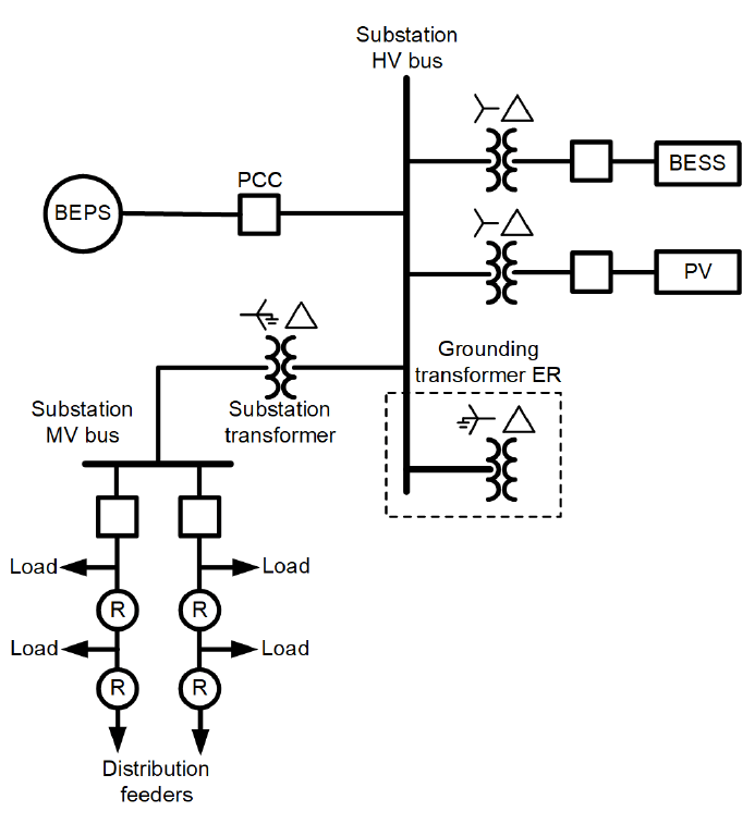
The substation transformer is the centerpiece of the substation, as it defines the HV side (possibly at transmission or subtransmission voltage levels) and the MV side (transforming the voltage level to standard distribution voltages) (2.4–35 kV).
In North America, the MV side of the substation transformer is solidly grounded, and the system is four wire. The four-wire feeders to the loads include the three-phase conductors and the neutral conductor. Further complicating matters, the neutral conductor is grounded periodically along the length of the feeder (i.e., multigrounded distribution network) [8]. It is a practice of distribution utilities to provide three-pole reclosers in key locations of the distribution feeder. The grounded nature of the system allows for the flow of significant ground fault current, making it possible to coordinate with inverse-time overcurrent relays (51P/51G) within the microgrid when the utility is connected.
The HV side of the substation is heavily dependent on the BEPS, which, in North America, is typically a solidly grounded source. The BESS and PV are connected to the HV side of the substation through ungrounded transformers.
If the PCC breaker opens with the BESS and PV sources online, the HV side of the substation becomes an unexpected ungrounded system. As explained in [9], if a ground fault occurred in the ungrounded part of the substation (HV), high voltages could be imposed on the healthy phases. To prevent this, a grounding transformer is provided, as shown in Fig. 11.
The grounding transformer in the HV bus is a permanent connection and a single source of grounding in the substation. The BESS and PV transformer grounds are not connected. The grounding transformer ground impedance is selected larger than the BEPS impedance. The ground impedance of the transformer is generally selected for several conditions:
1) to minimize the overvoltages,
2) to allow measurable levels of ground fault current for a relay connected in its neutral, and
3) to be large enough to shunt ground currents to the BEPS should the system be grid connected. The specifics for a grounding transformer size and type are not in the scope of this document.
B. Detecting Ground Faults
When connected to the BEPS, the PCC breaker is closed, and the ground fault contribution from the BEPS is significant, allowing a traditional inverse-time overcurrent (51) scheme to operate as expected.
When islanded, the BESS three-wire design is configured in grid forming with droop (GFMD) and provides the positive- and negative-sequence quantities for ground faults. The PV is a three-wire inverter, is configured as grid-following, and only provides positive-sequence current. The grounding transformer provides the zero-sequence path, allowing ground faults on the HV side to be detected at the grounding transformer neutral [7].
Ground fault detection on the MV side is aided by the solidly grounded neutral of the station transformer. When the PCC breaker is closed, the magnitude of the ground fault current in the feeders is relatively high and limited by the BEPS source impedance and the substation transformer, allowing for traditional inverse-overcurrent (51P/51G) coordination.
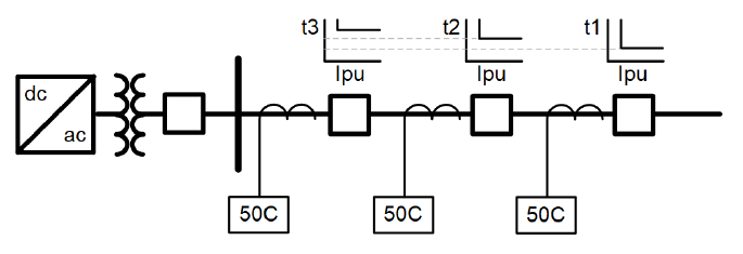
When islanded, only the inverter-based resource (IBR) generation is available, and the fault magnitudes are limited to a level of 1.2– 1.3 pu of the BESS inverter rating. The PV provides no current during a fault and likely trips offline. When islanded, a more sensitive scheme than the 51P/51G coordination is required, due to these low fault currents. In [7], an undervoltage controlled definite time overcurrent (50C) scheme is described. It qualifies the overcurrent element with the presence of low voltage. This works well, since the BESS pulls back voltage to limit current during overload conditions, such as faults. In the respective time frame of a fault, the BESS IBR is considered a current source when the PCC is closed and a voltage source when the PCC is open. Faults at every recloser are similar during the islanded operation of the BESS. Thus, during an islanded condition, there is no time-overcurrent (51) relationship, only a 50 current element with a 27 voltage supervision. Coordination is achieved using only different time delay settings in each recloser. A coordination time interval of 0.2 seconds is selected between subsequent series reclosers. Fig. 12 illustrates the distribution feeder.
V. TRANSPORTABLE MICROGRID EXAMPLE
A. Background
Transportable/mobile/portable microgrids are a collection of sources of power with the intention of plug-and-play. This system could be used to provide power where needed by quickly moving and interconnecting to a point to deliver power. Military forward operating bases, remote oil and gas drilling locations, mining, and disaster relief are common uses for these transportable microgrids.
Transportable microgrids can be viewed as emergency sources of power, which requires ground fault indication. Some designs are not effectively grounded, such as high-impedance grounding, and detect and alarm but not trip as one phase conductor becomes grounded.
Regardless of philosophy, all possible formations of DER should have a ground reference for detecting and preventing transient overvoltage from damaging equipment, as discussed in Section 1.3 of [10]. With portable equipment, one or more DERs (battery-backed IBR, utility, or generators) may be connected at any time.
B. Detection and Protection
The equipment protection for transportable microgrids draws from the principles discussed in the paper. Detection and protection for equipment in the microgrid depends on whether it is connected into an existing system as an SDS or NSDS.
There are two options for the installation of transportable microgrids. One is to treat it similarly to an NSDS and require that the system into which it is being interconnected use a three-pole ATS with a single point of neutral grounding at the utility transformer. The protection system for this configuration can be provided using neutral CTs to detect fault current returning to each source. In the case of a switched neutral system, such as a four-pole ATS, it may be useful to treat the transportable microgrid as a single SDS and provide neutral grounding at a single grounding electrode in addition to the grounding at the utility transformer. In configurations involving parallel operation with the utility, two or more neutral grounding bonding points may be required, and therefore, an MDGF scheme is needed for proper detection.
The transportable microgrid can be on a trailer, in a container, or placed on the ground adjacent to a building. Equipment grounding at these locations through a grounding electrode is provided. However, as noted previously, users must be careful not to create paths for fault current from other locations to travel through building equipment. Given that it may not be feasible to know the configuration of use for the transportable microgrid, it should be designed to fit into any system and provide adequate protection.
C. Example
In this project, the end user desires a containerized transportable microgrid to provide portable power to critical fixed plant loads. The transportable microgrid consists of a synchronous condenser (SC), two BESS IBRs, an electric vehicle charging station, and an auxiliary 120/208 V lighting panel. The transportable microgrid and the interconnection to the end user’s fixed plant electrical distribution is illustrated as a simplified single-line diagram in Fig. 13.
The SC is a 3,600-RPM design and has shaft-mounted weights providing kinetic energy storage for the grid. This increases fault currents, improves protection coordination, and keeps the adjacent inverters online as the frequency is stabilized due to kinetic ride through (inertia).
The transportable microgrid interfaces with an existing fixed plant electrical system consisting of a PCC fed by the utility power transformer, a diesel backup generator, and a photovoltaic DER system. A three-pole circuit breaker ATS is used to switch the diesel generator and the PCC. For economic and space constraints, the breakers are three-pole, and all systems are four-wire cables to be laid directly on the ground. In this project, the transportable microgrid is installed as an NSDS into the existing system, keeping the system ground at a single point at the utility transformer. Proper EGC grounding is performed through a ground bus in both the main and containerized transportable microgrid switchgear for equipment grounding. Care is taken in this installation to ensure that no break in the neutral or ground connections occurs. Any break of the neutral conductor results in an ungrounded system. Ground fault protection is provided by residually connected phase CTs and measured by the PPR (IN) current input.
VI. CHECKLIST
When designing any ground fault detection system, the following items should be verified in the design.
1. All possible island formations are determined, either by a PCC, ATS, or other means.
2. One or more grounds exists on each island.
3. The differential ground fault system is in place with multiple-point grounded systems, if paralleling distributed energy sources and/or BEPS.
4. All ground faults at all locations can be detected and discriminated from single-phase loads.
5. Adequate compliance and testing to NEC and other regulatory codes are applicable.
6. The inverter acts as a 1.0 pu current source for coordinating IBRs.
7. An SC is considered in the design to aid fault current production, as well as inrush and motor starting support.
8. A multifunction relay with SOE and oscillography recording capabilities is used to augment the circuit breaker between grid-connected and islanded operation to maintain coordination at these locations.
9. A protection expert is consulted if uncertain
VII. CONCLUSION
DER proliferation and interest in transportable microgrids continue to rise in the future. Understanding the differences between system and equipment grounding and the purpose of the two are crucial to the design of protection systems.
A relay-based ground fault detection and protection system was presented for several different examples where multiple sources with multiple grounds exist. The relay-based solution provides design simplicity and additional features offered by programmable logic features in the PPRs, such as bus synchronism checks for make-before-break switching, utility interruption detection, and many other benefits (e.g., oscillography, SOE, and several different communications protocols).
In this paper, we have given case studies and detailed the design process and methodology behind the reason for the selection of protection and detection of ground faults.
VIII. REFERENCES
[1] NFPA 70, National Electric Code (NEC).
[2] IEEE 3003.1.2019, IEEE Recommended Practice for Grounding of Industrial and Commercial Power Systems.
[3] P. Mike, “Avoiding Ground Fault Problems When Designing For Multiple Low Voltage Sources,” GE ESL
Magazine, 2005.
[4] Schneider Electric, “Ground-Fault Systems for Circuit Breakers Equipped with Micrologic Electronic Trip Units,” March 2016. Available: download.schneider-electric.com.
[5] D. Swindler and C. Fredericks, “Modified Differential Ground Fault Protection For Systems Having Multiple Sources And Grounds,” Schneider Electric, 1994.
[6] SEL-700GT Generator and Intertie Protection Relay Instruction Manual, Schweitzer Engineering Laboratories, 2021.
[7] R. Ruppert, R Schlake, S. Manson, F. Calero, and A. Kokkinis, “Inverter-Based Radial Distribution System
and Associated Protective Relaying,” proceedings of the 48th Annual Western Protective Relaying Conference, Spokane, WA, October 2021.
[8] J. Roberts, H. Altuve, and D. Hou, “Review of Ground Fault Protection Methods for Grounded, Ungrounded, and Compensated Distribution Systems,” proceedings of the 28th Annual Western Protective Relaying Conference, Pullman, WA, October 2001.
[9] K. Behrendt, “Protection for Unexpected Delta Sources,” proceedings of the 57th Annual Georgia Tech Protective Relaying Conference, Atlanta, GA, May 2003.
[10] IEEE 2030.9-2019, IEEE Recommended Practice for the Planning and Design of the Microgrid
IX. VITAE
Dirk Danninger received his MS and BS in engineering and systems control from Montana Technological University. He worked for over 24 years in the mining industry, where he held the positions of process engineer, electrical engineer, automation group manager, and electrical instrumentation and control engineering (EI&C) subject matter expert. Dirk can be reached at dirk_danninger@selinc.com.
Scott Manson received his MSEE from the University of Wisconsin–Madison and his BSEE from Washington State University. Scott is the engineering services technology director at Schweitzer Engineering Laboratories, Inc. (SEL). He is a registered professional engineer in 6 states and holds 20 patents. Scott can be reached at scott_manson@ selinc.com.
Fernando Calero is a principal engineer at Schweitzer Engineering Laboratories, Inc. (SEL) in the research and development (R&D) division with over 30 years in the industry. For 20 years, he was an application engineer in the SEL international organization. In 2020, he transferred to R&D and is currently working on projects related to renewable sources, protection, and control. He is a registered professional engineer in the state of Florida.
Ceeman B. Vellaithurai (S’09–M’12–SM’20) received the BE degree in electrical and electronics engineering from Anna University Tiruchirappalli, Tiruchirappalli, India, in 2011 and the MS degree in electrical engineering with specialization in power systems from Washington State University, Pullman, WA, USA, in 2013. He is currently working with Schweitzer Engineering Laboratories, Inc. (SEL), Pullman, as a protection engineer and pursuing his PhD from WSU. His research interests include real-time modeling and simulation of cyber-power systems. Ceeman has authored several technical papers with over 600 citations, patents, and is a registered professional engineer. Ceeman can be reached at ceeman_vellaithurai @selinc.com.
This paper was presented at the 69th Annual Petroleum and Chemical Industry Technical Conference, Denver, CO, September 26–29, 2022. Source URL: https://selinc.com/api/download/137170/

We love reading your blog! Your unique perspective and authentic voice make a difference in the world. Keep sharing, because your thoughts matter. Thank you for being you!
Thanks – TheDogGod
LikeLike
Thank you for your valuable comments!
LikeLike