Published by Grzegorz KOMARZYNIEC1, Tadeusz JANOWSKI2, Grzegorz WOJTASIEWICZ2, Michał MAJKA2, Politechnika Lubelska, Instytut Podstaw Elektrotechniki i Elektrotechnologii (1), Instytut Elektrotechniki w Warszawie (2)
Abstract. With switching on a superconducting transformer to the energetic network, a unidirectional current of high amplitude may appear. Maximal values of the current impulses following shortly one after the other may be several times higher than the critical current values for the superconductor used for making the transformer’s windings. Because of the resistive area propagation overheating of the superconducting tape occurs and that might lead to switching the transformer off working. In the present article the results for transformer HTS of 10 kVA power were presented.
Streszczenie. Włączeniu transformatora nadprzewodnikowego do sieci energetycznej może towarzyszyć prąd jednokierunkowy o dużej amplitudzie. Wartości maksymalne następujących krótko po sobie impulsów prądu mogą przekraczać wielokrotnie prąd krytyczny nadprzewodnika, z którego wykonano uzwojenia transformatora. W skutek propagacji strefy rezystywnej dochodzi do przegrzania taśmy nadprzewodzącej, co może skutkować wyłączeniem transformatora z eksploatacji. W artykule przedstawiono wyniki badań transformatora HTS o mocy 10 kVA. (Problemy cieplne w transformatorze HTS spowodowane przepływem prądu włączania)
Keywords: inrush current, transformer, superconducting, temperature.
Słowa kluczowe: prąd włączania, transformator, nadprzewodnictwo, temperatura.
Introduction
In certain conditions, with switching the transformer onto the energetic network a high value unidirectional current will flow in the windings [1]. Its first impulse may be 40 times higher than the transformer’s rated current. The following impulses are attenuated by the transformer’s windings resistance and the powering circuit’s resistance [2]. Depending on the transformer’s power, this current’s duration may be equal to from several to more than ten thousand periods of the feeding voltage.
Inrush current, in the transformer’s power circuit, causes a series of disadvantageous phenomena [3]. In superconducting transformers (HTS) the flow of this current may cause loss of the superconductive windings state as a result of exceeding critical superconductor values: density of the current, field intensity, temperature.
Due to the heterogeneous structure of the superconductor, the weakest area in the windings becomes the origin of resistive area. In the place of that area’s occurring, the inrush current flows through the stabilizer generating heat by power losses on its resistance, according to the Jouel’s law. The resistive area propagation onto neighboring regions of the superconductor depends on the heat spread speed in the tape, cooling system efficiency and the inrush current wave’s shape.
The windings overheating threatens with the superconductor’s failure and the transformer’s switching off of working [4][5]. Continuing degradation of a second generation superconductor is observed at the temperature of over 600K. Keeping windings at cryogenic temperature is one of the most complex issues in the HTS transformers exploitation [6][7].
Object of research
The trials were executed on a one phase HTS transformer of 10kVA power. The core was done as wound and cut with metal sheet PN ET52-27 of induction B=1.75 T with H=10 A/cm and loss of P=0.8 W/kg at B=1T and f=50 Hz. The transformer’s primary and secondary voltage windings were made of superconducting tape Super Power SCS4050 (RE)BCO of effective value of critical current of 80 A in temperature of 77K in self field. The tape’s bulk was 0.1 mm, the width 4 mm. The windings were isolated by wrapping the superconducting tape with kapton. The windings geometry was shown in the Figure 1. The transformer’s windings are being cooled by liquid nitrogen to reach the temperature of 77K. The transformer’s core works at room temperature. The rated parameters were given in the Table 1.
Table 1. The rating of the transformer
Measurement
Measurements were taken in the system presented in Figure 2. The current’s flow was registered indirectly, by measuring the voltage drop on the shunt 60A, 60mV and exactness class 0.5. The data acquisition was realized with measuring card National Instruments USB-6212, using application written at LabVIEW. Switching the transformer on was done with a thyristor system switching the transformer on at the moment of passing of the power network’s voltage the zero value.

In Figure 3 we presented registered inrush current flows i(t) and voltage upw(t) measured at the HTS transformer’s primary windings. Since the transformer’s switching on, the voltage changes sinusoidally. The highest measured peak value of the TrHTS transformer’s inrush current is 178 A.
Table 2. The parameters inrush currents

HTS transformers inrush current decay time is longer as compared with transformers with copper windings [8][9]. The examined transformer’s registered unidirectional current decay time was 350 ms.
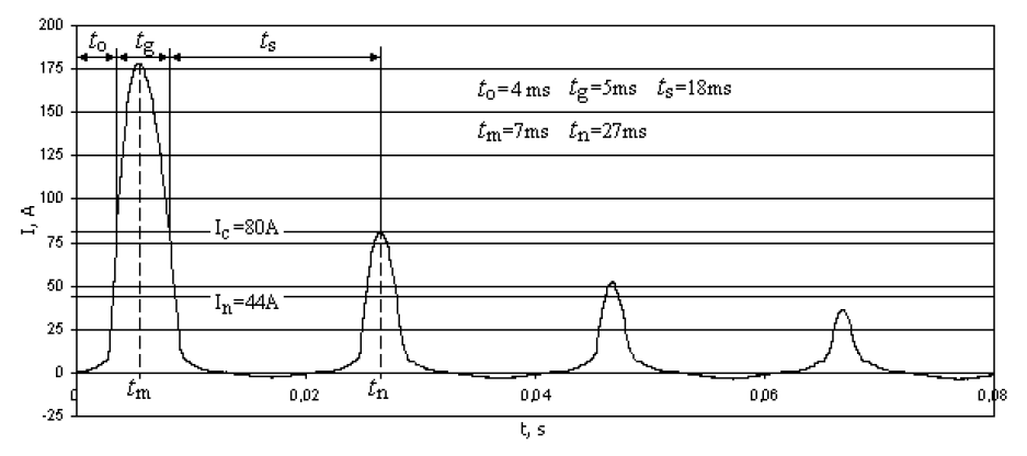
The sufficient condition of going of the superconducting tape into resistive state is exceeding the value of superconductor’s critical current. Exceeding critical current value of tape SCS 4050 (Ic=80 A) occurs after t0=4 ms (Fig. 4) as measured since switching the transformer onto the power network. The time tg in which the exceeding occurs is 5 ms. In this period it is expected that the tape loses its superconductive properties and its temperature grows.
The circuit with HTS transformer showed rapid attenuation of unidirectional impulses down to current values lower than the superconductor’s critical current. The first impulse’s amplitude exceeds the critical current (80 A) of the superconducting tape SCS4050 (Fig. 4) by 98 A and the transformer’s rated current (44 A) by 134 A. The second impulse coming after 0.02 s is comparable to the critical current value (80 A) and the peak value of the third impulse (50 A) (after 0.04 s) is by 30 A lower than the tape’s critical current value.
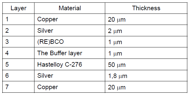
Endurance of the SCS4050 tape for thermal failure depends on distribution of the current’s density in each layer at resistive condition. The construction of the tape are shown in Table 3.
Table 3. Layer structure of tape SCS4050
Based on the resistivity of the individual materials, you can calculate the percentage of the current dispersed into individual layers. Assuming the materials are homogeneous the tape’s structure was pictured by parallel connections between resistances representing each layer (Fig. 5) [10].
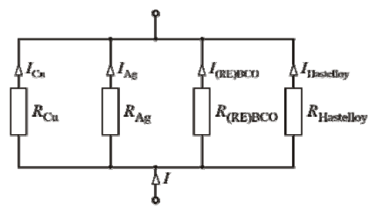
In the superconducting state all the current flows through superconductor. Calculations show, that in resistive state of the SCS4050 tape, at temperature of 77K, 89% of current flows through Cu layer, 9.4% through the Ag layer and 1.5% through the Hastelloy layer. With temperature growth, the resistance of layers materials changes. In addition, the reflow of current changes. At 293K we get 88.7%, 9.5%, 1.5% respectively.
The main conductor at the resistive state is copper. At moment tm (Fig. 4) when the inrush current reaches its maximal value, a current of 158 A flows through the copper layer and that gives the momentary current density of 987 A/mm2 (Tab. 4). This value is 318 times higher than the maximal acceptable value of current density for copper in the air (3.1 A/mm2). A higher momentary density is observed for the silver layer. At moment tm it is 1112 A/mm2.
Return of the HTS transformer’s winding to its superconducting state happens when three conditions occur simultaneously: (1) intensity of the outer magnetic field is lower than its critical value; (2) the inrush current maximal value is lower than the critical value; (3) superconductor’s temperature is lower than the critical temperature.
The first condition, because of great critical values of the 2G superconductors’ field intensity, is met for the entire inrush current lasting time. The second condition is met for the time ts=18 ms (Fig. 4) between consequent impulses of the unidirectional component. By this time the cooling process of the superconductor to cryogenic temperature takes place. If the third condition is met depends on the cooling system efficiency in tome ts. The cooling intensity strongly depends on temperatures difference between liquid nitrogen and the cooled surface. In case of the smallest heat currents and the smallest temperatures differences the heat is transferred due to natural convection. With raise in superconducting tape’s temperature vacuolar boiling of the cryogenic liquid occurs until in the peripheral layer the gas form of nitrogen appears. This worsens conditions for transformer’s windings cooling and lowers isolation durability against breakthrough.
Table 4. The instantaneous current density in layers for time tm (resistive superconducting state)

The third condition is hard to measure by simply measuring the temperature. The tape’s temperature can be estimated by electrical rates measuring. The medial resistivity of the SCS4050 tape in normal state is interesting, estimated for different temperatures. It can be calculated from the equation:
where: pi, Si–resistivity and cross sectional area of the i-th material of the superconducting tape, S – total cross-sectional area of the superconducting tape. Knowing the characteristic p=f(T) the superconducting tape’s temperature can be established by measuring electrical rates.

The medial resistivity of the SCS4050 tape at 77K, calculated from the (2) equation is:

The resistivity at 293K known from the direct measurements is:
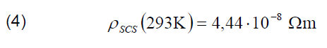
That gives the conclusion, that change in SCS4050 tape’s temperature by 216K, results in more than 10 times’ raise in medial resistivity. During lasting of inrush current that kind of raise in resistance have not been noted along the whole of the winding (55 cm). Because the current at time tg exceeds critical current it can be expected, that a hard to spot, local loss of superconductivity occurs.
The examined HTS transformer went through numerous switching on trials. Despite exceeding the critical value by inrush current and a great exceed in acceptable current density for the copper stabilizer no failure of the SCS 4050 tape have been noted.
Conclusions
The methods in designing conventional transformers, with copper or aluminum windings, do not take into account the inrush current phenomenon. This experiment showed that the phenomenon may cause problems in switching on the superconducting transformer. The single unidirectional current impulse of great momentary density observed during switching on a transformer HTS of 10 kVA power, exceeding critical current, may lead to thermal damage in superconducting windings. The experiment showed, that it is difficult to establish the maximal temperature value and spot its appearing in the windings.
The loss of HTS transformer’s superconducting state (with raise in windings temperature in safe limits) may limit negative impact of inrush current. Raise in circuit resistance due to raise in windings resistance lowers the inrush current’s amplitude and its duration [11][12].
HTS transformers should be designed in the way that they stand certain inrush current for a certain period of time without exceeding the acceptable temperature for the transformer’s superconducting windings. There are no respective norms for the time being.
The research was conducted in scope of the project “Analysis of inrush current phenomenon and the phenomena related in superconducting transformers”. The project was financed with means of National Science Center given with the decision no. DEC- 2012/05/D/ST8/02384
The superconducting transformer was constructed in scope of research project no: N510526439, “Elaborating the model design for 1-phase superconducting transformer with windings made of HTS tape of 2nd generation”.
REFERENCES
[1] E. Jezierski, Transformatory, WNT, Warszawa (1983)
[2] M. Jamali, M. Mirzaie, S. Asghar Gholamian, Calculation and analysis of transformer inrush current based on parameters of transformer and operating condictions, Electronics and Electrical Engineering, Electrical Engineering, no. 3(109), (2011)
[3] R. A. Turner, K. S. Smith, Resonance Excited by Transformer Inrush Current in Inter-connected Offshore Power Systems, IEEE Industry Applications Society Annual Meeting, Edmonton, Canada, October (2008)
[4] G. Wojtasiewicz, T. Janowski, S. Kozak, J. Kozak, M. Majka, B. Kondratowicz-Kucewicz, Tests and Performance Analysis of 2G HTS Transformer, IEEE Transactions on Applied Superconductivity, vol. 23, issue: 3, part: 2, (2012)
[5] G. Wojtasiewicz, T. Janowski, S. Kozak, J. Kozak, M. Majka, B. Kondratowicz-Kucewicz, Experimental Investigation of the Model of Superconducting Transformer With the Windings Made of 2G HTS Tape, IEEE Transactions on Applied Superconductivity, vol. 22, issue: 3, (2012)
[6] S. S. Kalsi, Applications of High Temperature Superconductors to Electric Power Equipment, John Wiley and Sons Ltd, April (2011)
[7] J. K. Sykulski, C. Beduz, R.L. Stoll, M.R. Harris, K.F. Goddard, Y. Yang, Prospects for large high-temperature superconducting power transformers: conclusions from a design study, Electric Power Applications, IEE Proceedings, vol. 146, issue: 1, (1999)
[8] G. Wojtasiewicz, G. Komarzyniec, T. Janowski, S. Kozak, J. Kozak, M. Majka, B. Kondratowicz-Kucewicz, Inrush Current of Superconducting Transformer, IEEE Transaction on Applied Superconductivity, vol. 23, issue: 3, June (2013)
[9] G. Komarzyniec, T. Janowski, G. Wojtasiewicz, M. Majka, J. Kozak, S. Kozak, B. Kondratowicz-Kucewicz, Prąd włączania transformatora nadprzewodnikowego, Przegląd Elektrotechniczny, no. 9, (2013)
[10] M. Sjöström, B. Dutoit, and J. Duron, Equivalent Circuit Model for Superconductors, IEEE Transactions on Applied Superconductivity, vol. 13, no. 2, June (2003)
[11] H. Shimizu, K. Mutsuura, Y. Yokomizu, T. Matsumura, Inrush-Current-Limiting with high Tc superconductor, IEEE Transactions on Applied Superconductivity, vol. 15, no. 2, June (2005)
[12] S. Hun-Chul, K. Chul-Hwan, R. Sang-Bong, K. Jae-Chul, H. Ok-Bae, Superconducting Fault Current Limiter Application for Reduction of the Transformer Inrush Current: A Decision Scheme of the Optimal Insertion Resistance, IEEE Transactions on Applied Superconductivity, vol. 20, no. 4, August (2010)
Authors: dr inż. Grzegorz Komarzyniec, E-mail: g.komarzyniec@pollub.pl, Politechnika Lubelska, Instytut Elektrotechniki i Elektrotechnologii, ul. Nadbystrzycka 38a, 20-618 Lublin,
prof. dr hab. inż. Tadeusz Janowski, E-mail: t.janowski@pollub.pl,
dr inż. Grzegorz Wojtasiewicz, E-mail: g.wojtasiewicz@iel.waw.pl,
dr inż. Michał Majka, E-mail: m.majka@iel.waw.pl, Instytut Elektrotechniki, ul. Pożarskiego 28, 04-703 Warszawa
Source & Publisher Item Identifier: PRZEGLĄD ELEKTROTECHNICZNY, ISSN 0033-2097, R. 90 NR 2/2014. doi:10.12915/pe.2014.02.04
