Published by Electrical Installation Wiki, Chapter J. Overvoltage protection – Principle of lightning protection
General rules of lightning protection
Procedure to prevent risks of lightning strike
The system for protecting a building against the effects of lightning must include:
• protection of structures against direct lightning strokes;
• protection of electrical installations against direct and indirect lightning strokes.
The basic principle for protection of an installation against the risk of lightning strikes is to prevent the disturbing energy from reaching sensitive equipment. To achieve this, it is necessary to:
• capture the lightning current and channel it to earth via the most direct path (avoiding the vicinity of sensitive equipment);
• perform equipotential bonding of the installation;
This equipotential bonding is implemented by bonding conductors, supplemented by Surge Protection Devices (SPDs) or spark gaps (e.g., antenna mast spark gap).
• minimize induced and indirect effects by installing SPDs and/or filters.
Two protection systems are used to eliminate or limit overvoltages: they are known as the building protection system (for the outside of buildings) and the electrical installation protection system (for the inside of buildings).
Building protection system
The role of the building protection system is to protect it against direct lightning strokes.
The system consists of:
• the capture device: the lightning protection system;
• down-conductors designed to convey the lightning current to earth;
• “crow’s foot” earth leads connected together;
• links between all metallic frames (equipotential bonding) and the earth leads.
When the lightning current flows in a conductor, if potential differences appear between it and the frames connected to earth that are located in the vicinity, the latter can cause destructive flashovers.
The 3 types of lightning protection system
Three types of building protection are used:
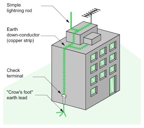
The lightning rod (simple rod or with triggering system)
The lightning rod is a metallic capture tip placed at the top of the building. It is earthed by one or more conductors (often copper strips) (see Fig. J12).
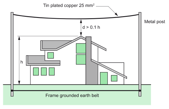
The lightning rod with taut wires
These wires are stretched above the structure to be protected. They are used to protect special structures: rocket launching areas, military applications and protection of high-voltage overhead lines (see Fig. J13).
The lightning conductor with meshed cage (Faraday cage)
This protection involves placing numerous down conductors/tapes symmetrically all around the building. (see Fig. J14).
This type of lightning protection system is used for highly exposed buildings housing very sensitive installations such as computer rooms.

Consequences of building protection for the electrical installation’s equipment
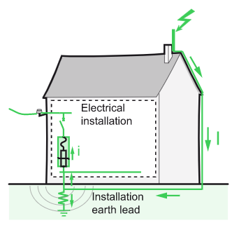
50% of the lightning current discharged by the building protection system rises back into the earthing networks of the electrical installation (see Fig. J15): the potential rise of the frames very frequently exceeds the insulation withstand capability of the conductors in the various networks (LV, telecommunications, video cable, etc.).
Moreover, the flow of current through the down-conductors generates induced overvoltages in the electrical installation.
As a consequence, the building protection system does not protect the electrical installation: it is therefore compulsory to provide for an electrical installation protection system.
Lightning protection – Electrical installation protection system
The main objective of the electrical installation protection system is to limit overvoltages to values that are acceptable for the equipment.
The electrical installation protection system consists of:
• one or more SPDs depending on the building configuration;
• the equipotential bonding: metallic mesh of exposed conductive parts.
Implementation
The procedure to protect the electrical and electronic systems of a building is as follows.
Search for information
• Identify all sensitive loads and their location in the building.
• Identify the electrical and electronic systems and their respective points of entry into the building.
• Check whether a lightning protection system is present on the building or in the vicinity.
• Become acquainted with the regulations applicable to the building’s location.
• Assess the risk of lightning strike according to the geographic location, type of power supply, lightning strike density, etc.
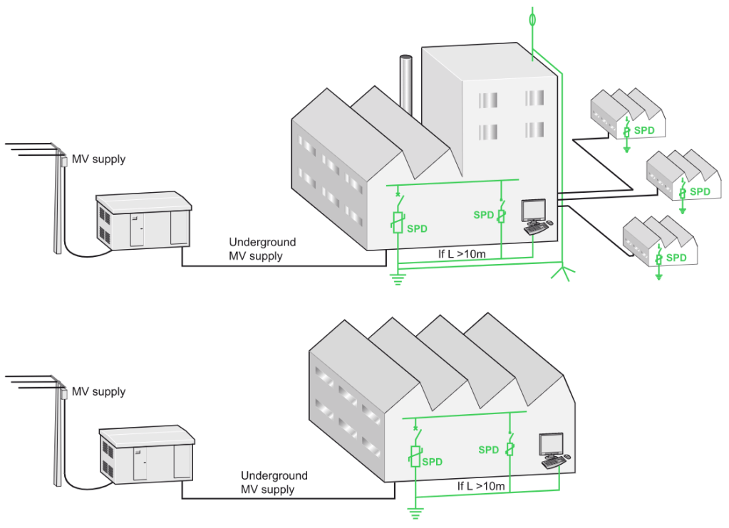
Solution implementation
• Install bonding conductors on frames by a mesh.
• Install a SPD in the LV incoming switchboard.
• Install an additional SPD in each sub-distribution board located in the vicinity of sensitive equipment (see Fig. J16).
The Surge Protection Device (SPD)
Surge Protection Devices (SPD) are used for electric power supply networks[1], telephone networks, and communication and automatic control buses.
The Surge Protection Device (SPD) is a component of the electrical installation protection system.
This device is connected in parallel on the power supply circuit of the loads that it has to protect (see Fig. J17). It can also be used at all levels of the power supply network.
This is the most commonly used and most efficient type of overvoltage protection.
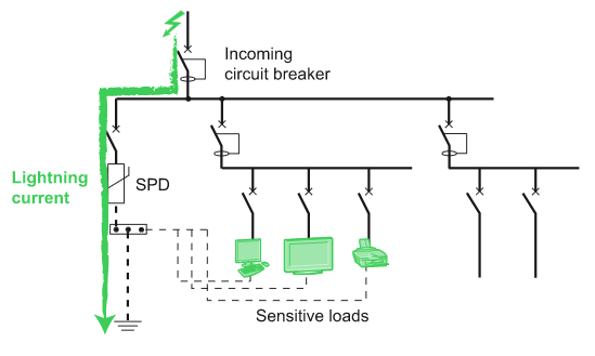
SPD connected in parallel has a high impedance. Once the transient overvoltage appears in the system, the impedance of the device decreases so surge current is driven through the SPD, bypassing the sensitive equipment.
Principle
SPD is designed to limit transient overvoltages of atmospheric origin and divert current waves to earth, so as to limit the amplitude of this overvoltage to a value that is not hazardous for the electrical installation and electric switchgear and controlgear.
SPD eliminates overvoltages
• in common mode, between phase and neutral or earth;
• in differential mode, between phase and neutral.
In the event of an overvoltage exceeding the operating threshold, the SPD
• conducts the energy to earth, in common mode;
• distributes the energy to the other live conductors, in differential mode.
The three types of SPD
Type 1 SPD
The Type 1 SPD is recommended in the specific case of service-sector and industrial buildings, protected by a lightning protection system or a meshed cage.
It protects electrical installations against direct lightning strokes. It can discharge the back-current from lightning spreading from the earth conductor to the network conductors.
Type 1 SPD is characterized by a 10/350 µs current wave.
Type 2 SPD
The Type 2 SPD is the main protection system for all low voltage electrical installations. Installed in each electrical switchboard, it prevents the spread of overvoltages in the electrical installations and protects the loads.
Type 2 SPD is characterized by an 8/20 µs current wave.
Type 3 SPD
These SPDs have a low discharge capacity. They must therefore mandatorily be installed as a supplement to Type 2 SPD and in the vicinity of sensitive loads.
Type 3 SPD is characterized by a combination of voltage waves (1.2/50 μs) and current waves (8/20 μs).
SPD normative definition

Note 1: There exist [T1] + [T2]SPD (or Type 1 + 2 SPD) combining protection of loads against direct and indirect lightning strokes.
Note 2: some [T2] SPD can also be declared as [T3].
Characteristics of SPD
International standard IEC 61643-11 Edition 1.0 (03/2011) defines the characteristics and tests for SPD connected to low voltage distribution systems (see Fig. J19).
Common characteristics
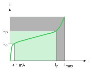
• Uc: Maximum continuous operating voltage
This is the A.C. or D.C. voltage above which the SPD becomes active. This value is chosen according to the rated voltage and the system earthing arrangement.
• Up: Voltage protection level (at In)
This is the maximum voltage across the terminals of the SPD when it is active. This voltage is reached when the current flowing in the SPD is equal to In. The voltage protection level chosen must be below the overvoltage withstand capability of the loads. In the event of lightning strokes, the voltage across the terminals of the SPD generally remains less than Up.
• In: Nominal discharge current
This is the peak value of a current of 8/20 µs waveform that the SPD is capable of discharging minimum 19 times[2].
Why is In important?
In corresponds to a nominal discharge current that a SPD can withstand at least 19 times[2]: a higher value of In means a longer life for the SPD, so it is strongly recommended to chose higher values than the minimum imposed value of 5 kA.
Type 1 SPD
• Iimp: Impulse current
This is the peak value of a current of 10/350 µs waveform that the SPD is capable of discharging of discharging at least one time[3].
Why is Iimp important?
IEC 62305 standard requires a maximum impulse current value of 25 kA per pole for three-phase system. This means that for a 3P+N network the SPD should be able to withstand a total maximum impulse current of 100kA coming from the earth bonding.
• Ifi: Autoextinguish follow current
Applicable only to the spark gap technology. This is the current (50 Hz) that the SPD is capable of interrupting by itself after flashover. This current must always be greater than the prospective short-circuit current at the point of installation.
Type 2 SPD
• Imax: Maximum discharge current
This is the peak value of a current of 8/20 µs waveform that the SPD is capable of discharging once.
Why is Imax important?
If you compare 2 SPDs with the same In, but with different Imax: the SPD with higher Imax value has a higher “safety margin” and can withstand higher surge current without being damaged.
Type 3 SPD
• Uoc: Open-circuit voltage applied during class III (Type 3) tests.
Main applications
• Low Voltage SPD
Very different devices, from both a technological and usage viewpoint, are designated by this term. Low voltage SPDs are modular to be easily installed inside LV switchboards.
There are also SPDs adaptable to power sockets, but these devices have a low discharge capacity.
• SPD for communication networks
These devices protect telephone networks, switched networks and automatic control networks (bus) against overvoltages coming from outside (lightning) and those internal to the power supply network (polluting equipment, switchgear operation, etc.).
Such SPDs are also installed in RJ11, RJ45, … connectors or integrated into loads.
Notes
1. find out more in application examples such as SPD for EV charging application, SPD for photovoltaic applications and SPD application example in Supermarket
2. Test sequence according to standard IEC 61643-11 for SPD based on MOV (varistor). A total of 19 impulses at In:
• One positive impulse
• One negative impulse
• 15 impulses synchronised at every 30°on the 50 Hz voltage
• One positive impulse
• One negative impulse
3. for type 1 SPD, after the 15 impulses at In (see previous note):
• One impulse at 0.1 x Imp
• One impulse at 0.25 x Imp
• One impulse at 0.5 x Imp
• One impulse at 0.75 x Imp
• One impulse at Imp
Source URL: https://www.electrical-installation.org/enwiki/Principle_of_lightning_protection
